Sulphur 414 Sep-Oct 2024
30 September 2024
Channelling in SRU converters
SRU TROUBLESHOOTING
Channelling in SRU converters
This troubleshooting case study describes an incident at one of the sulphur recovery units at BPCL Kochi Refinery, India. Following a maintenance turnaround of the unit in 2022, unusually high H2S and SO2 were observed at the outlet of the Claus section. This created an additional load on the tail gas reactor, which led to frequent plugging in the quench column and frequent outages in the tail gas unit, creating environmental and reliability issues in the unit. The activities to identify the root cause of the incident are described and the measures to solve the problem are shared.
Design basis
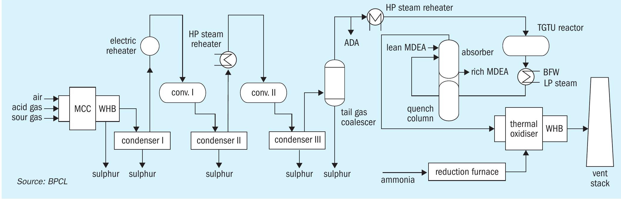
Bharat Petroleum Corporation Limited (BPCL) Kochi Refinery has three sulphur recovery units SRU1 (140 t/d), SRU2 (80 t/d) and SRU3 (2 x 337 t/d). SRU3 has two identical trains (Train A and Train B) consisting of a Claus section, tail gas treatment unit (TGTU) and thermal oxidiser with a common amine regeneration facility (see Fig. 1). SRU3 is designed to process acid gases from the amine regeneration unit and sour gases from the phenolic sour water units (SWS1) and non-phenolic sour water units (SWS2) with a design sulphur recovery of 99.9% (min).
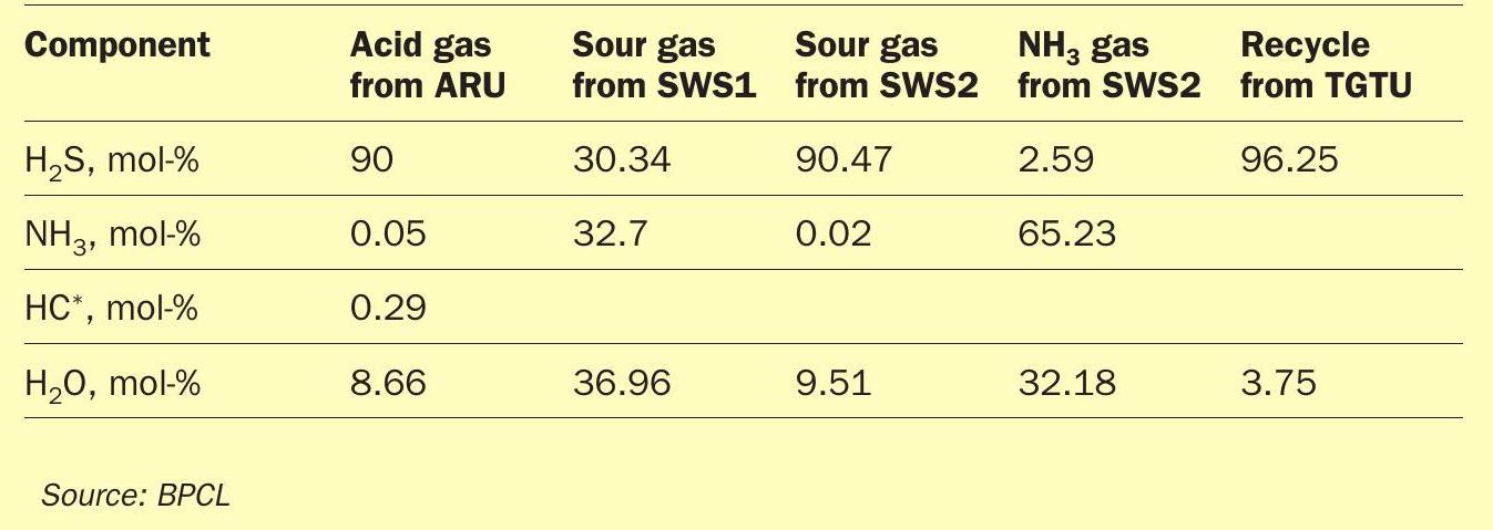
Table 1 shows the design basis of the SRU Claus section and Table 2 shows the design conditions of the TGTU.
Background
SRU3 Train A and B were shut down for maintenance and inspection (M&I). All equipment was opened and inspected, planned M&I jobs were completed and catalyst was replaced in all converters including the TGTU reactor. SRU3 converter 1 contains one layer of activated alumina and another layer of titania-based catalyst. Converter 2 contains only activated alumina.
Post turnaround observations
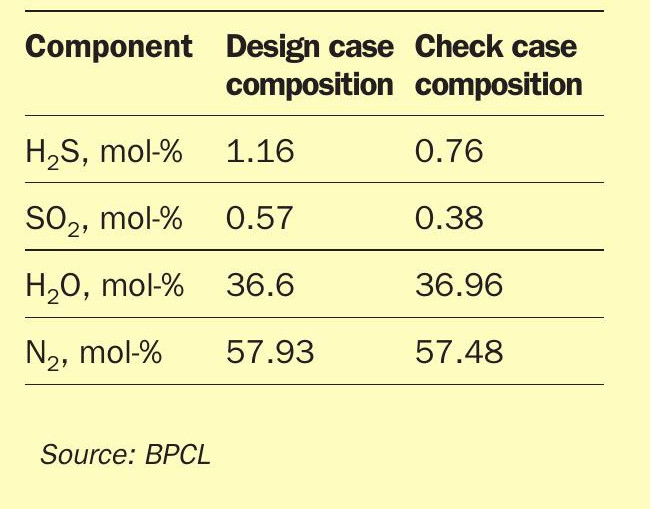
Post turnaround, the unit was taken back in line in the third week of October 2022. SRU3 Train B had higher molar concentrations of H2S and SO2 observed at the air demand analyser (ADA). As shown in Table 3, there was a significant deviation from the normal operation which forms the basis of this article and the troubleshooting undertaken to resolve the issues.
Additional observations were as follows:
- SO2 checked with Dräger tubes at the TGTU reactor outlet was always < 1.5 ppm (indicating no SO2 slippage).
- Minimal ammonia injection to the quench column had to be kept (previously always closed) to maintain the pH in Train B quench water.
- Sulphur vapour differential in the ADA measured at the TGTU inlet was found to be around 0.0075 wt-% both before and after the turnaround – indicating no additional carryover of sulphur vapour to the TGTU.
- A yellow sulphur layer was observed at the quench column inlet line during isolation. Gray colour colloidal sulphur is present in the quench column packings.
- Post turnaround, quench column plugging was observed frequently leading to outages.
- The Claus converters outlet temperature was lower than the last bed layer temperature.
Troubleshooting
The troubleshooting carried out to investigate the issue is listed below.
General actions recommended by catalyst vendor
- The air demand ratio (H2S to SO2 ) was varied from ~ 2 to 4, but SO2 was always >0.65 mol-%.
- Strawman sample points de-plugged in condenser 1 (inlet and outlet) and sample showed higher H2S than design.
- ADA action tuned by instrument personnel.
- Ammonia from cylinders / caustic of 5% strength were used separately to maintain the pH in the quench column to avoid contamination from the ammonia stream on a trial basis.
Air demand analyser (ADA) calibration
During this period, the ADA was calibrated several times and found to be okay. The analyser readings were cross-checked by testing gas samples in the lab and using Dräger tubes. Both methods showed similar values, indicating that a faulty ADA could be ruled out.
Input streams to the quench column
No slippage of SO2 from the TGTU reactor was observed but the quench column pH was dropping. DM water was analysed, and no acidic components were present.
Coalescer performance
It was suspected that sulphur was slipping from the tail gas coalescer to the TGTU. The differential pressure (DP) transmitter across the demister was faulty providing no reliable information about the condition of the demister inside the coalescer. Given the unit’s history of demister failure, inspecting this demister was deemed critical for identifying the root cause. The tail gas coalescer was later opened during a shutdown opportunity and the demister was found to be in intact condition. The connected spare and main sulphur run-down lines were checked, and no plugging issues were detected.
Converter performance
The temperatures across the converter beds indicated normal activity in both SRU Train A and B converters, which was also confirmed by the catalyst vendor during on-site evaluation. The catalyst vendor recommended online catalyst rejuvenation to enhance the catalyst performance. The converter 1 inlet temperature was increased to 285°C from 260°C and the converter 2 temperature was increased to 220°C from 195°C keeping the bed outlet temperatures below 355°C for converter 1. These conditions were maintained for 12 hours. The TGTU reactor inlet temperature was increased to ~ 240°. However, this catalyst rejuvenation did not resolve the downstream quench column plugging issues.
Licensor study and recommendations
The TGTU licensor also analysed the data to identify the root cause and couldn’t firmly conclude the reason. Engineers India Limited (EIL), SRU licensor, was entrusted with conducting a detailed analysis of the problem. EIL conducted test runs on 27 and 28 September 2023, simulated the data and identified that low conversion in SRU3 Train B is due to channelling of acid gas in the converters. Various cases had been considered for matching the plant converter bed temperatures and air demand analyser values.
No channelling case simulation study of converters
For an inlet temperature of 271°C, the simulated bed temperature would be approximately 334°C. However, plant data shows the bed temperatures are near 328°C. This means the process gas temperature at the inlet of converter 1 is approximately 264°C as per the simulation (see Fig. 2).
For an inlet temperature of 195°C in converter 2 and with no issues of channelling in converter 1, the bed temperatures would be approximately 225°C. However, plant data shows the bed temperatures are near 238°C (see Fig. 3).
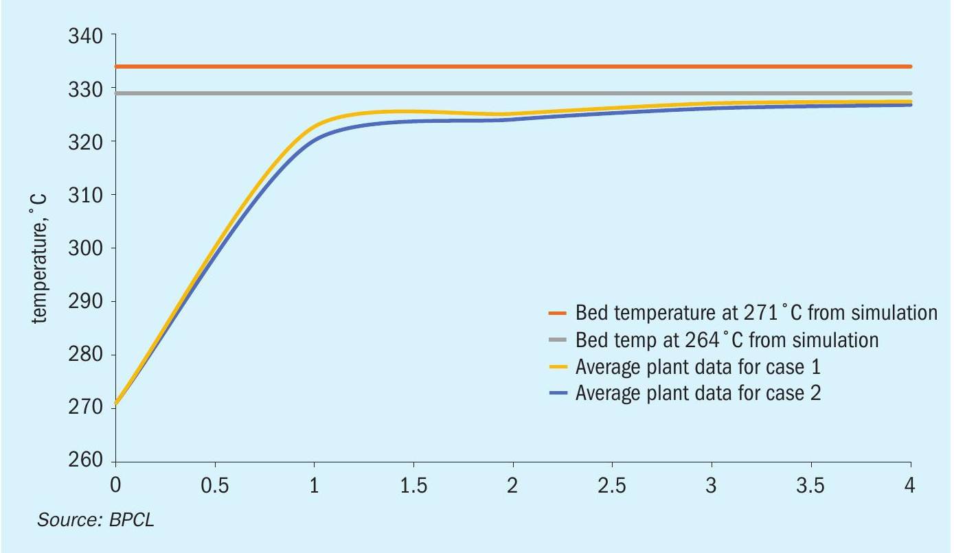
Loss in catalyst activity
Considering that the catalyst has been loaded just one year before, it can be considered as relatively fresh catalyst. Also, as there is an exotherm in both converters, the case of loss in catalyst activity has been ruled out.
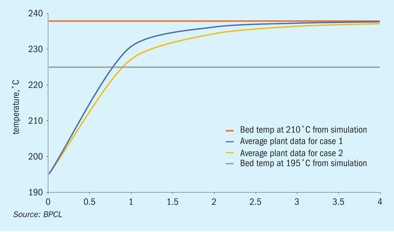
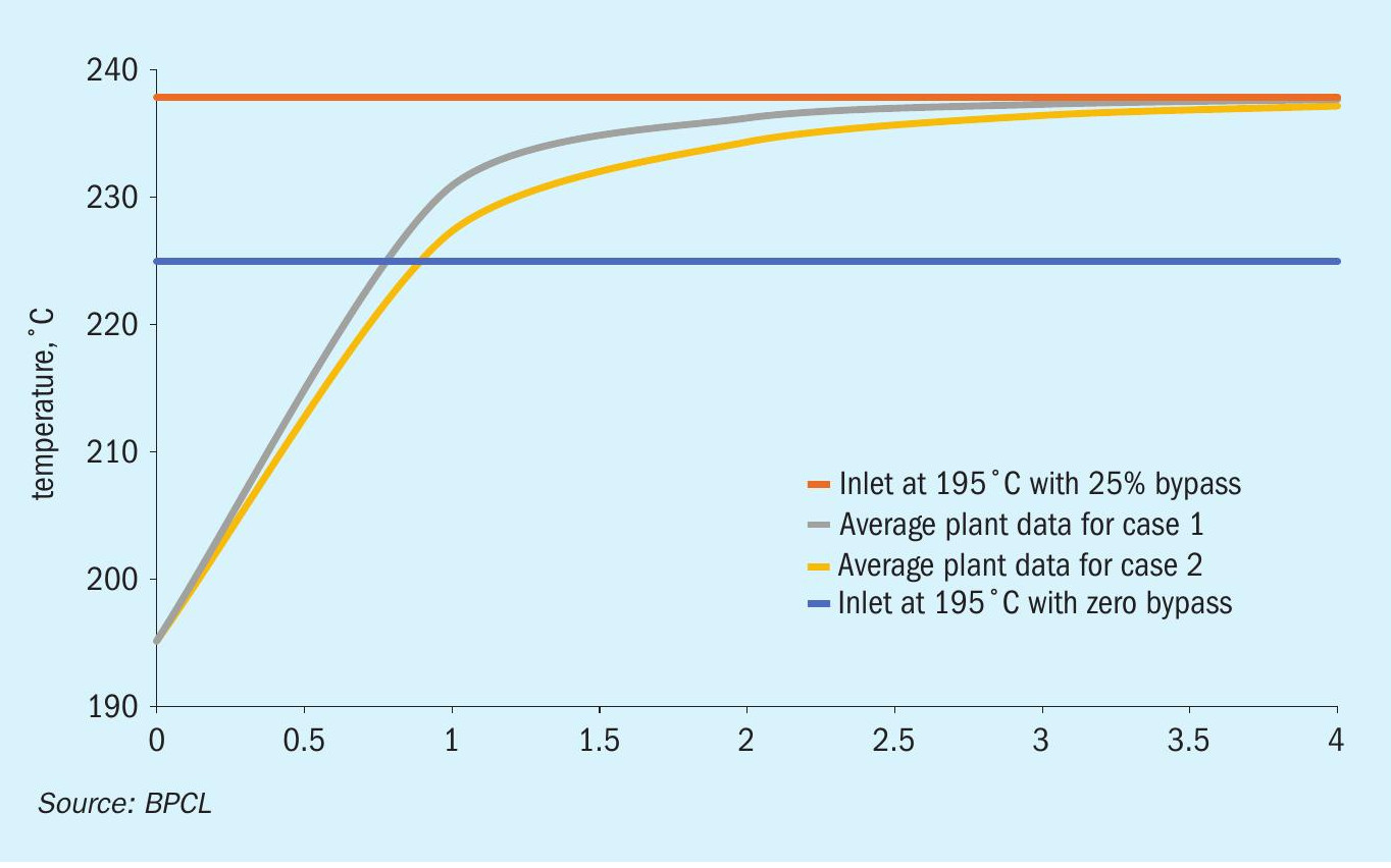
Effect of channelling
Various bypass fractions have been considered and it has been observed that with approximately 25% of bypass in both converters, ADA values and converter 2 bed temperatures match plant data (see Fig. 4).
Post this simulation study EIL gave the following observations and recommendations:
- Channelling in both converters in Train B was predicted.
- Both Claus converters in SRU Train B to be opened for inspection.
- After inspection, catalyst and support balls to be unloaded from both reactors and mesh to be reinstalled as per recommendation and catalyst to be reloaded:
– One layer of wire mesh between the grating and support balls with proper overlap and fixed to the first strip plate. A floating wire mesh i.e. not connected to the converter wall, between the support balls and catalyst is provided.
– Catalyst support balls to be loaded up to 100 mm height on wire mesh and catalyst to be loaded above the support balls as per PDS requirement.
– Gap between refractory and wire mesh to be filled with ceramic rope around the periphery of wire mesh.
Based on EIL’s recommendations, Train B SRU was shut down for converter mesh modifications in February 2024.
Observation
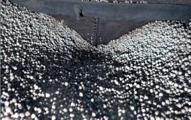
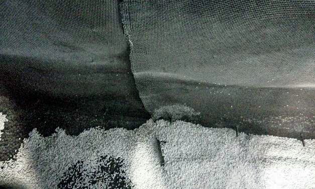
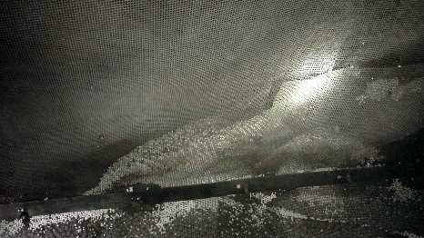
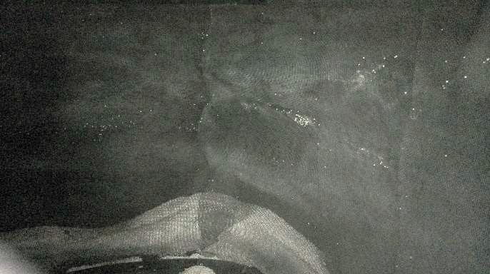
After opening the converter, it was observed that the bed profile was flat, which infers that there was no undulation due to maldistribution of feed gas. Also, it was observed that at multiple locations around the perimeter, where catalyst touches the mesh, catalyst had caved in and pit-like structures had formed. From these locations, it is understood that gas is bypassing the catalyst bed. Also, after catalyst unloading, it was observed that the gap between the mesh and the refractory wall was significant enough for process gas bypassing the catalyst (see Figs. 5-8).
Post mesh modification
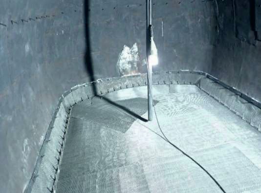
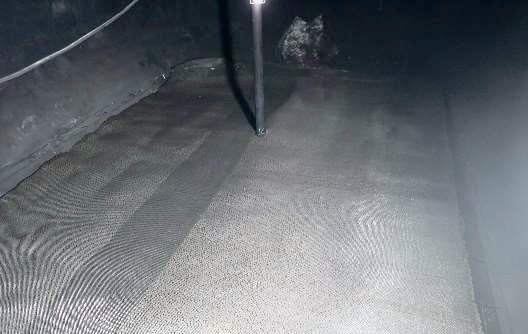
The existing mesh has been completely removed in SRU3 Train B converters, relaid extending up to 200 mm from the support grid as shown in Figs. 9 and 10. A layer of mesh has been laid between the ceramic balls and the catalyst for easy unloading and separation. The mesh has been fixed with studs welded to the retainer plate. A mesh partition has been provided between the ceramic balls and the remaining catalyst layers without fixing the mesh to the refractory wall. This aids unloading of alumina/titanium based catalyst without mixing with ceramic balls.
Impact of mesh modification on converter efficiency
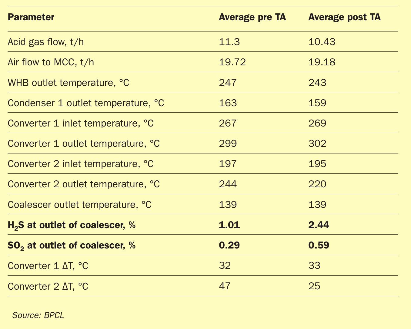
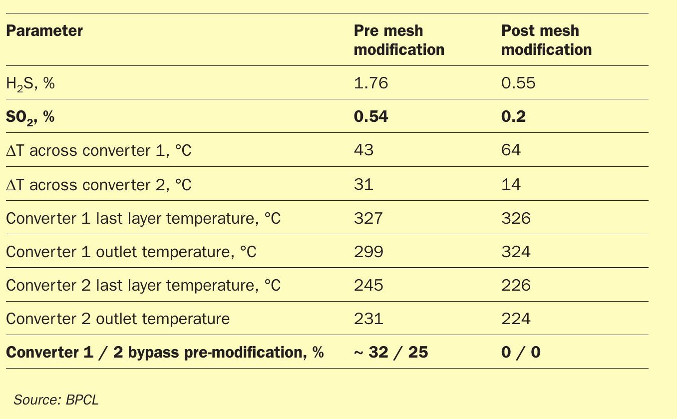
Following the mesh modification, H2S and SO2 levels at the TGTU reactor inlet had reduced (see Table 4). The improvements can be summarised as follows:
- Reduction in H2S and SO2 levels: H2S and SO2 values reduced to 0.5 mol-% and 0.25 mol-% compared to previous values of 2 mol-% and 0.65 mol-% respectively.
- Differential temperature indications: The increase in ΔT across converter 1 and the decrease in ΔT across converter 2 indicating no channelling in converters.
- No plugging issues across the quench column in TGTU.
Conclusion
Activities carried out to identify the root cause of high SO2 and H2S at the outlet of the Claus section revealed that channelling of the Claus converter was the critical issue. Post mesh modifications in SRU3 Train B converters were carried as per licensor recommendations. The following results were observed: l SRU Claus section efficiency increased from 93% to approximately 96%. l SO2 /H2S load to tail gas treatment section reduced by 50%. l No quench column plugging issue observed in TGTU Train B. l Approximately 30% reduction in hydrogen consumption in TGTU Train B. l Reduced stack SOx emissions.