

Sulphur 413 Jul-Aug 2024

31 July 2024
Carbon capture in the sulphur value chain
DECARBONISATION
Carbon capture in the sulphur value chain
Readers of Sulphur magazine have always been at the forefront of operating, designing, researching, and troubleshooting process units in the sulphur value chain. However, more recently, with the emergence of net zero initiatives by international conventions and governments (e.g. the Paris agreement), the push for decarbonisation in our industry has been on the rise. Ganank Srivastava of Bryan Research & Engineering takes a look at the bigger picture and examines ways to reduce carbon footprint in sour gas facilities.
Conventional sour gas plant process scheme
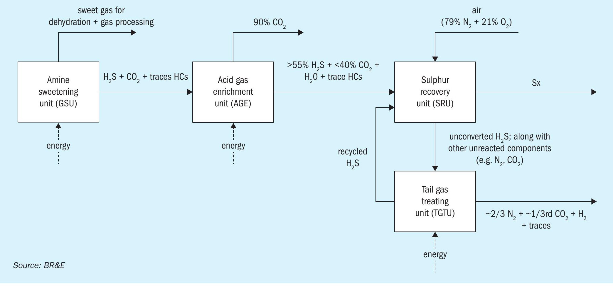
The treatment section is the heart of any sour gas processing facility. Usually, the hydrocarbons entering the plant travel through the following process units to prepare contaminant free natural gas (C1 ) for safe transportation and consumption: gas sweetening/GSU (to remove acidic H2S, CO2) → gas dehydration/GDU (to remove H2O) → turboexpander/DeC1 (to remove NGL). Responsible and compliant energy companies usually further invest in a sulphur recovery unit (SRU) that safely disposes of the acidic gaseous contaminants removed in the amine sweetening section (by converting harmful H2 S to marketable sulphur, Sx). The frontend of a SRU also involves a burning step, where a portion of the acid gases react with O2 from air to produce SO2; which serves as a key reactant for subsequent sulphur production. Due to process inefficiencies, trace hydrocarbons making their way to SRUs, will be converted to unavoidable CO2 during this step too.
It is important to keep in mind that the CO2 (from either the acid gas mix or combustion step) and N2 (from air) do not participate in or contribute towards the sulphur recovery reactions of H2S → Sx. They are both inerts in the process that reduce efficiency and simply occupy volume.
To enhance the long-term cost benefits of such units, some operators therefore modify the aforementioned scheme with two additional units: an acid gas enrichment unit (to purify the H2S content in the acid gas mixture entering the sulphur recovery unit) and tail gas treating units (to recycle unconverted H2S from the sulphur recovery unit back to the beginning of the unit). The final block flow diagram of a representative facility is shown in Fig. 1.
Tracking key CO2 exit points – decarbonisation opportunities
The above process scheme shows us that CO2 (our key-component for this analysis), has three key exit points: the AGE vent line, the TGT vent line, and all the emissions generated from heat sources providing energy to run the plant. Their rough operating conditions can be summarised by Table 1 using representative facilities.
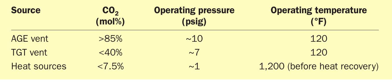
The table gives us three straight-forward conclusions:
- Strictly from a partial pressure and operating conditions viewpoint, heat sources will be the most capex and opex heavy opportunity when it comes to effectively capturing CO2 . However, this might be the most prevalent source of carbon emissions from oil and gas facilities.
- The AGE vent is a rich CO2 line that needs minimal investment to recover.
- The TGT vent is an opportunity that has a relatively rich CO2 concentration and can be further optimised to enhance cost benefits for carbon capture.
Modifications and technologies to enhance cost-effectiveness of carbon capture
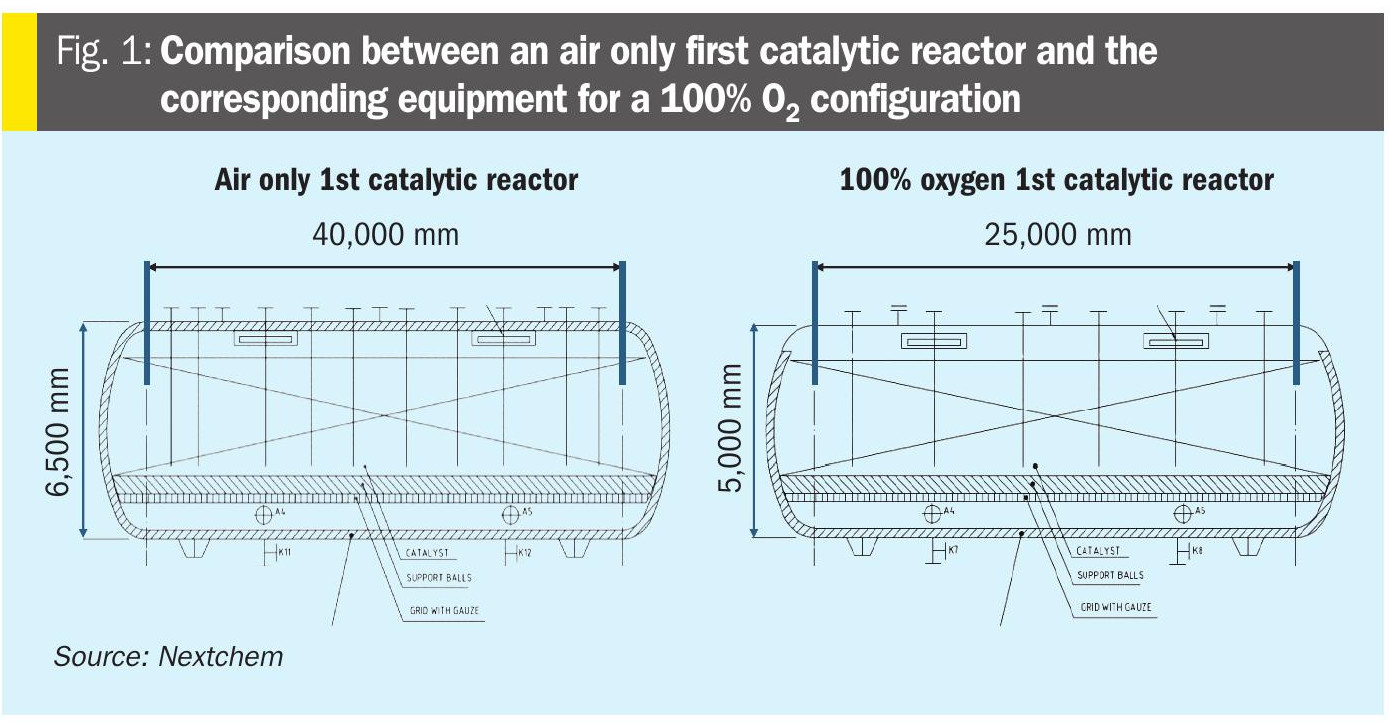
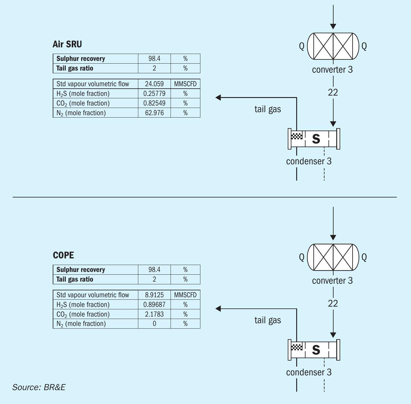
Claus Oxygen Enhanced Process Expansion (COPE) is a SRU technology that is gaining a lot of traction in recent times. It is a process improvement that not only reduces the capital/size footprint of a sulphur plant but also opens the door for cost-effective carbon capture. This is achieved by using enriched or pure O2 (80 to 100 %) instead of air in the front-end of an SRU during the acid gas burning step. This completely removes inert N2 in the sulphur recovery section of the value chain. A ProMax® process simulation model demonstrates that this can reduce actual volumes of an SRU by almost 60% (see Fig. 2). This would mean that one O2-enriched SRU is roughly equivalent to two air-based SRUs in terms of overall performance (potentially even overcompensating the opex to produce pure O2).
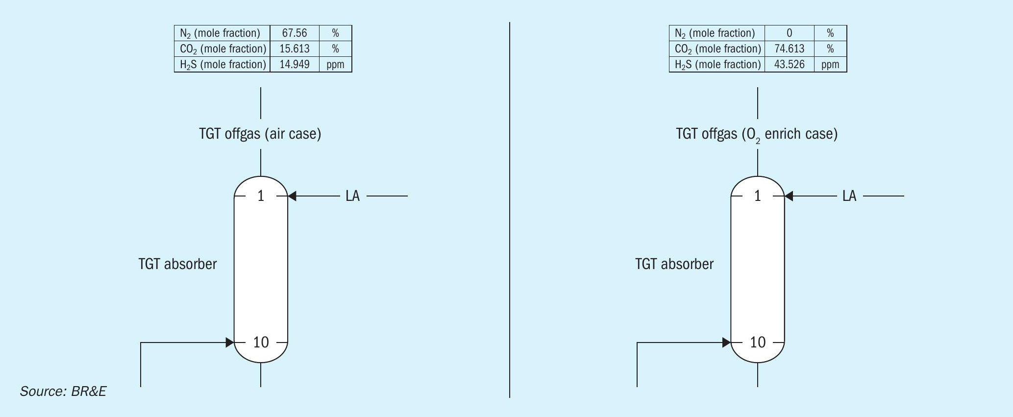
The benefits of having no N2 in the process (see Fig. 3) cascades over and increases the CO2 concentration in the TGT vent line from <40 mol-% to beyond >75 mol-% (making the operating conditions of this stream similar to an AGE vent line). This effectively reduces the scope of carbon capture opportunities in the sour gas value chain to two – heat sources (with <7.5 mol-% CO2, 1 psig) and TGT/AGE vent lines (with >75 mol-% CO2, 7.5 psig).
Available carbon capture technologies in the market today can be broadly categorised into three types: chemical solvents (e.g., amines), physical solvents (e.g., DEPG) and non-solvent options (e.g., cryogenic cold flashing). In terms of published reports in the literature on technology maturation, successfully implemented CO2 capture plants, and operational/financial efficiency, there definitely seems to be a tilt in favour towards solvent-based capture systems.
Several different solvents are available for capturing CO2. The diagram in Fig. 4, extracted from Bryan Research & Engineering’s BRE231 training manual, summarises general guidelines for best solvent selection.
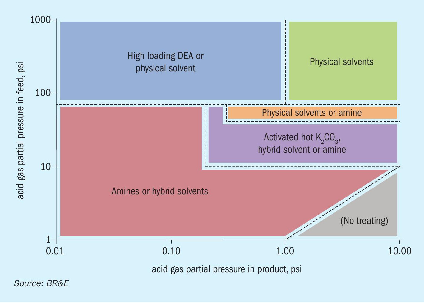
One can see that the two opportunities discussed in this article lie below the 10-psi mark on the y-axis where amines will be the best choice.
MEA has long been considered as the industry baseline generic amine solvent for low-pressure carbon capture systems. Being a primary and therefore aggressive solvent, it is known to effectively extract CO2 from a mixture of other gases even at extremely low partial pressures. However, the heat of reaction between MEA and the acid gases is large which leads to larger energy requirements for solvent regeneration.
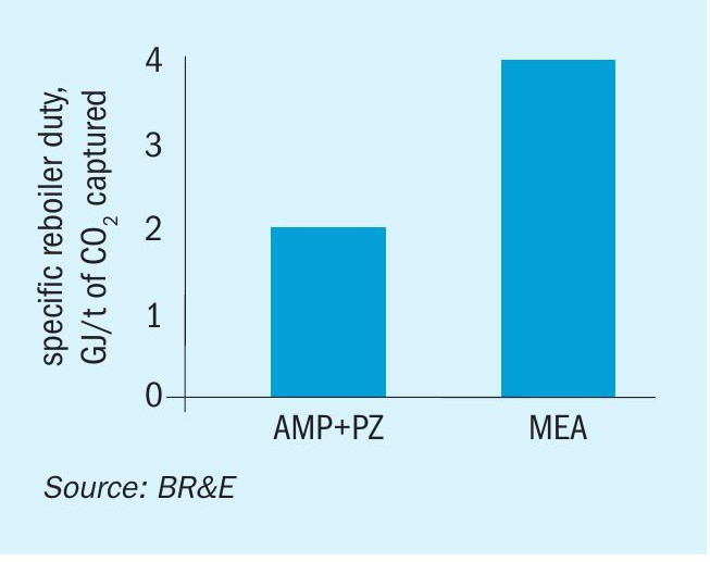
In comparison, the AMP + PZ blend, is starting to create a lot of noise for the right reasons as a potential new baseline. AMP, a sterically hindered yet highly reactive primary amine, acts as the CO2 “holder”; while PZ, an amine activator, acts as the CO2 “grabber”. Running a ProMax® process simulation model comparing AMP + PZ versus MEA for capturing >95% CO2 from a LP stream (representative of a heat source opportunity) showcases energy savings of ~50% (see Fig. 5).
Another thing to keep in mind is the formation of degradation products in the presence of contaminants like O2 and SOx. These are probably contaminants in the flue gas along with CO2, when fuel is burnt for generating energy. MEA, because of its aggressive and highly reactive nature tends to have the highest rate of degradation product formation. On the contrary, AMP is known to have a slower rate making it a slightly more viable option when activated with PZ.
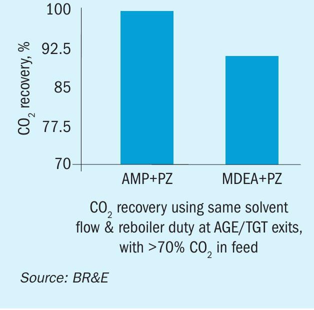
It is noteworthy to point out that for decarbonisation opportunities on AGE/ TGT exits, where CO2 is slightly more concentrated (>75%) and there is no presence of O2 or SO2, reactive primary solvent options like MEA or AMP/PZ may not be required. More stable, popular, easily monitorable options like aMDEA (MDEA + PZ) might also work. Even though MDEA is a tertiary and less aggressive solvent, the higher partial pressure of CO2 in these opportunities can make it a potential candidate, especially when PZ is added in the range of 5-7 wt-%. As one can see from Fig. 6, MDEA + PZ can still achieve around 90% CO2 recovery when stacked up against AMP+PZ for an AGE/TGT exit opportunity using the exact same flow rate and reboiler duty.
Cold flash or cryogenic systems might also be a strong candidate to recover CO2 from such concentrated streams (into pure CO2 liquid); though sufficient power may be required to compress the gas to increase its dew point for cost-effective condensation, while care must also be taken to dehydrate the gas to avoid ice formation during cooling. A thorough techno-commercial analysis of cold flash technology was not carried out for the purpose of this article as it was qualified as a non-mature and expensive alternative to solvent based options. However, licensors can be approached to evaluate this opportunity at rich CO2 exit lines.
Additional key considerations
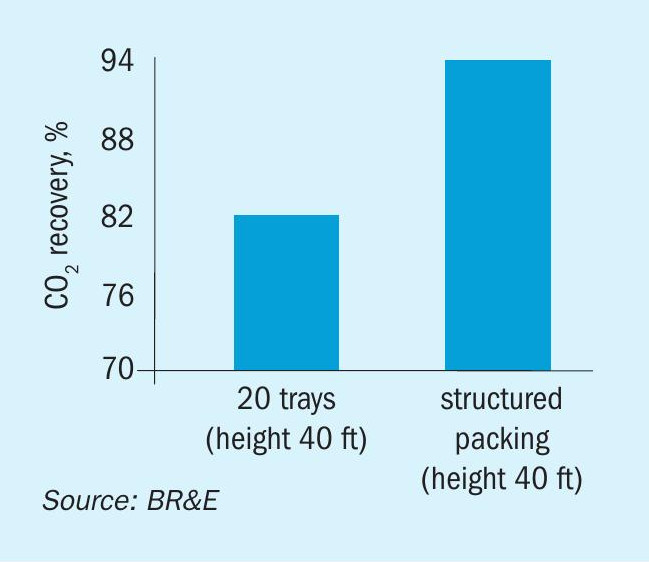
While designing carbon capture units, it is also crucial to keep in mind some additional considerations, specifically with regards to mass transfer efficiency. At low pressures, it is imperative that the hardware selected provides the optimum mass transfer of CO2 from the vapour phase to the aqueous amine. As can be seen from a the representative case in Fig. 7 for flue gas carbon capture at atmospheric pressure, structured packings provide better performance compared to trays.
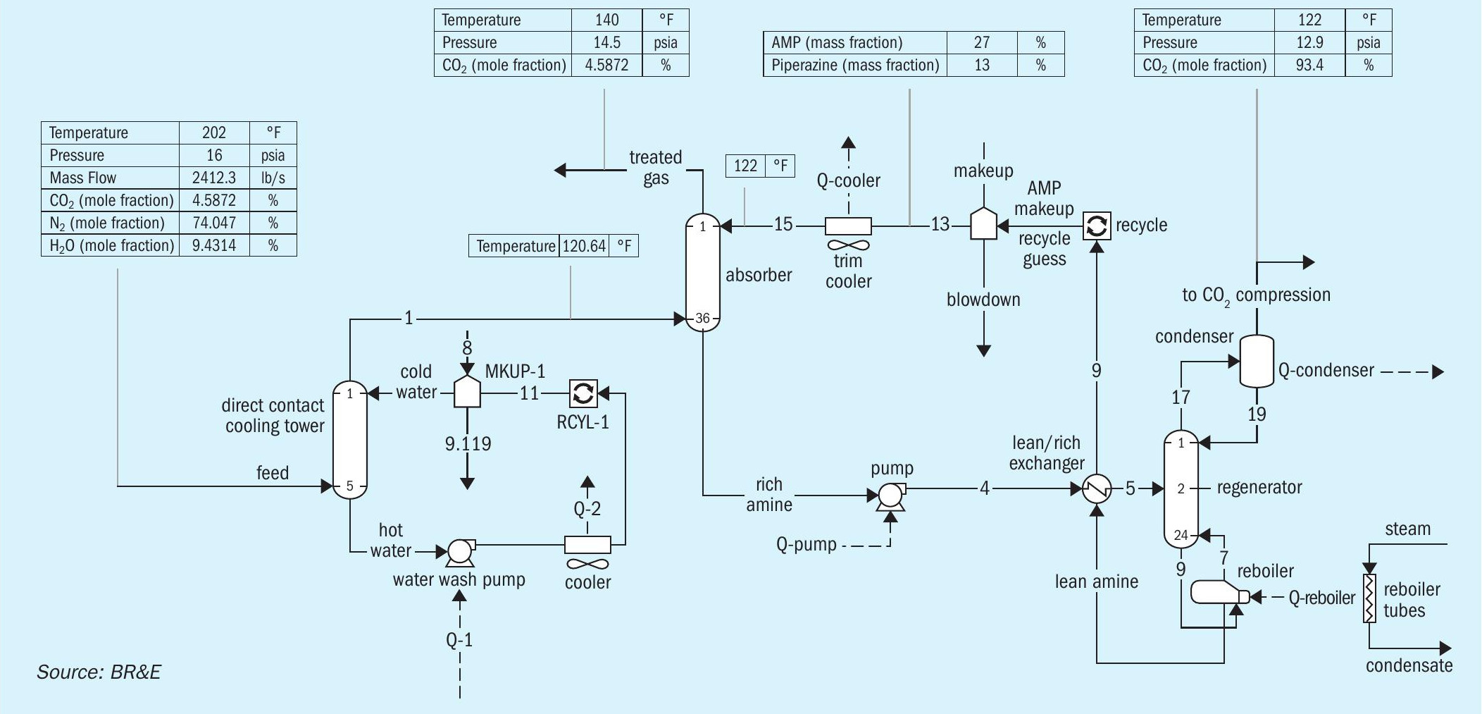
Another design consideration to keep in mind is the temperature and contaminants present in the CO2 exit line that is routed for removal. CO2-amine reactions are exothermic in nature and therefore extremely hot lines can disturb this equilibrium in an unfavourable direction. In hot flue gas scenarios, it is therefore critical to install a direct contact cooling tower to bring the temperature of the gas closer to ambient conditions before sending it to an amine-based carbon capture unit.
Contaminants in the feed can also render an amine unit to fail over time. High amounts of SO2 in feeds (even in ppm amounts) can result in the formation of non-regenerable heat stable sulphites over time making the amine solvent ineffective by being tied up as a salt. A remedy for this is to add caustic wash, saltwater wash, or plain water as possible pretreatment options along with the DCC loop.
Fig. 8 shows a complete process flow diagram of a proposed carbon capture facility.
Conclusions
A conventional sour gas facility is an energy intensive process. In the push for decarbonising this value chain, three exit points were identified as opportunities to capture CO2 from. However, just like other units of a gas plant (e.g. AGRU, GDU, AGE, SRU), a carbon capture unit also requires energy to operate and therefore has its own “footprint”. It almost seems counter-intuitive to even propose such a unit. However, it’s the volume balancing and net zero game that need to be focused on. By utilising the right technologies and modifications this can be achieved in a cost-effective manner. Some suggestions discussed in this article are:
- COPE or oxygen-enhanced SRUs;
- using AMP/PZ and variants over MEA at low pressures to save on solvent regeneration costs;
- using packed towers (to provide better CO2 mass transfer at LP) instead of trays;
- SOx pretreatment (to prevent amine degradation/HSS).
References