Nitrogen+Syngas 400 Mar-Apr 2026
19 March 2026
A regenerative amine system for CCS
BLUE HYDROGEN
A regenerative amine system for CCS
A novel high-pressure regeneration (HPR) process for carbon capture in blue hydrogen applications is introduced as a new offering for reducing costs. The process combines a specially formulated solvent with a heat integration network to deliver the separated carbon dioxide at high pressure while reducing capital costs and equipment sizes.
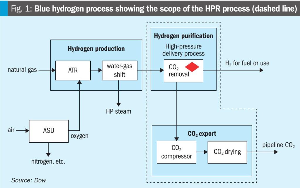
The global low emissions hydrogen market is expected to grow substantially over the next decade, driven by growth in use as fuel as well as its conventional uses in refining and ammonia production. A key contributor to the growing low emissions hydrogen supply is projected to be blue hydrogen production, which requires capture of CO2, distinguishing it from grey hydrogen production in which CO2 is vented to the atmosphere. Policy is essential for driving market growth and carbon capture costs need to be reduced, as conventional methods for capturing CO2 in grey hydrogen applications are not optimised for the new constraint of compression and dehydration required in blue hydrogen production. It is within this context that Dow introduces the HPR process as a new offering for reducing CCS costs in blue hydrogen applications. Fig. 1 shows a high-level block diagram air of a blue hydrogen process, including the scope of the HPR process. The feedstock fuel is usually methane-rich natural gas. A reformer, typically an autothermal reformer (ATR), generates synthesis gas (syngas) from the fuel and an oxygen feed, supplied by an air separation unit (ASU). The syngas is then fed to a water-gas-shift (WGS) reactor, wherein more hydrogen (H2) is generated and CO is converted to carbon dioxide. The resulting gas stream is referred to as shifted syngas and is then fed downstream to the CO2 capture unit after heat recovery.

While many technology choices are available for CO2 capture from shifted syngas, this article compares solvent-based absorption processes using aqueous amine solutions. The CO2 capture unit removes CO2 from the shifted syngas stream and delivers it to the compression train where it is dried and compressed to pressures typically exceeding 150 bar and transported for storage or use. The resulting hydrogen stream may be used as fuel for combustion, or upon further cleanup, as a feedstock for other low carbon products such as blue ammonia.
The CO2 capture and compression sections represent a significant portion of the total capital and operating costs of a blue hydrogen production facility. Recent reports show as much as one-third of the capital cost resides in the amine unit and compression section, with about half of the combined amine unit + compressor costs attributable to the compressor itself. The main cost drivers for the compression section are a product of the properties of the feed stream: the relatively low delivery pressures, and thus gas density, create the need for large equipment to process the gas which is further compounded by the fact that the CO2 is water-saturated (in aqueous amine processes), which dictates stainless steel as the material of construction. Hence, delivery of low-pressure CO2 from the CO2 capture section will necessarily lead to high compression capital and power requirements.
Delivering CO2 to the compression train at as high a pressure as possible holds promise as a method to reduce compressor costs by minimising or even eliminating the capital and operating costs of low-pressure compression stages. This requires operating the vessels contained within the regeneration section of an amine flowsheet at the highest pressures economically attainable, considering the limits of the feed pressure, solvent properties and stability, and other factors affecting process cost. The present article introduces an evolution of the amine absorption process built around this concept and performs a high-level cost comparison to conventional amine processes.
Available processes, qualitative benefits, and trade-offs
The general process for using aqueous amines to remove acid gases, including carbon dioxide, from gaseous mixtures was first patented in 1930 by Bottoms. Since that time, aqueous amine solvents have found widespread use in acid gas removal applications, including natural gas purification, oil refining, synthesis gas purification, and carbon capture from flue gases. The classic process for removing acid gases from a gas stream using aqueous amines is shown in Fig. 2 (a).
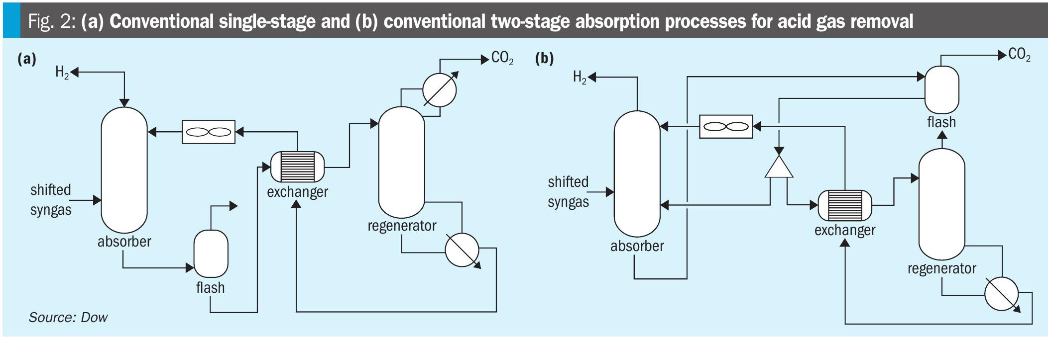
Conventional single-stage process
The process shown in Fig. 2(a) is referred to as the conventional single-stage absorption process due to the absorber having a single feed point for the solvent and hence a single mass transfer contacting section for CO2 absorption. It has the advantage of simplicity, as the equipment count and process complexity are the lowest of the processes considered in this article. Further, the high CO2 concentrations typical of shifted syngas streams require a relatively high ratio of solvent circulation rate to feed gas rate (L/G ratio) compared to that of other commonly encountered acid gas removal applications (e.g., pipeline natural gas treating for liquified natural gas production). Unlike post-combustion applications where the absorber diameter is set almost entirely by the gas rate, the high L/G ratio seen in blue hydrogen CCS can cause the liquid rate to have a significant influence on absorber size, which tends to be the highest capital cost item within the amine unit. Because the entirety of the solvent is fully regenerated in the conventional single-stage process, the circulation rate is the lowest of the processes considered in this article, leading to the lowest capital cost of the absorber and amine unit.
The conventional single-stage process has two significant drawbacks, however. The first, which has already been mentioned, is that like all conventional amine processes the CO2 is delivered from the regeneration section at a low pressure – typically 5-15 psi(g). This leads to high capital and operating costs for the compressor. The second disadvantage arises due to the requirement to meet the H2 product specifications in the treated gas, which are typically 100 ppmv or lower for blue H2 applications. Such low CO2 concentration can only be met if the gas is in contact with a solvent that has been thoroughly stripped of CO2 (i.e, a solvent with a very low CO2 loading – defined as the ratio of moles of CO2 to moles of amine in the solvent). Since all of the solvent is fed to the top of the absorber, this requires that the entire flow of solvent be fully regenerated to this low CO2 loading, which leads to the highest steam consumption of the processes considered. In turn, operating costs of the single-stage process are relatively high.
Conventional two-stage process
In situations where the high steam consumption of the single-stage process is prohibitive, an alternative is offered by the two-stage absorption process shown in Fig. 2 (b). The idea behind this process is to perform bulk removal of CO2 with a solvent that is flash regenerated (i.e., pressure swing only, requiring no steam), and to only fully regenerate that portion of the solvent which is necessary to meet the product specification. The absorption thus occurs in two stages: (1) a top polishing section where the lean solvent removes the last remaining amount of CO2 down to the product specification, and (2) a bulk removal section, where a partially regenerated (semi-lean) solvent performs bulk CO2 removal. The exact ratio of the flow of semi-lean solvent to lean solvent varies by case and can be optimised for site-specific steam and capital costs.
The advantage of the two-stage process is it requires considerably less steam than the single-stage process. When desired, the reboiler of the regenerator can often be driven entirely from process waste heat from the shifted syngas itself, thus consuming zero steam. The drawback is that the cyclic capacity (difference between the rich and lean loading) of the semi-lean solvent is much lower than the fully regenerated solvent of the single-stage process. Hence, the circulation rate of the two-stage process (sum of the lean and semi-lean flows) is much higher, driving capital costs higher for the absorber and other equipment. Further, the two-stage process retains the problem of low CO2 delivery pressure and thus leads to high compression capital and power requirements.
High-pressure regeneration process
A new process offering, the HPR process, is shown in Fig. 3. In this process, the rich solvent is introduced into a heat exchange network to maximise heat recovery and thus increase the amount of flashed CO2 in a series of high-pressure (HP) and medium-pressure (MP) flashes prior to the regenerator. These flash vessels deliver gas into the compression system at a higher net density, decreasing the overall hydraulic sizing and power requirements for the compressor. The HP flash is delivered to the suction of third stage compression, MP flash to the suction of second stage compression, and the LP regenerator to the suction of first stage compression. There is a LP steam auxiliary heater prior to the flashes for startup purposes and intermittent use, but is it not required in normal operation for all instances of the HPR design.
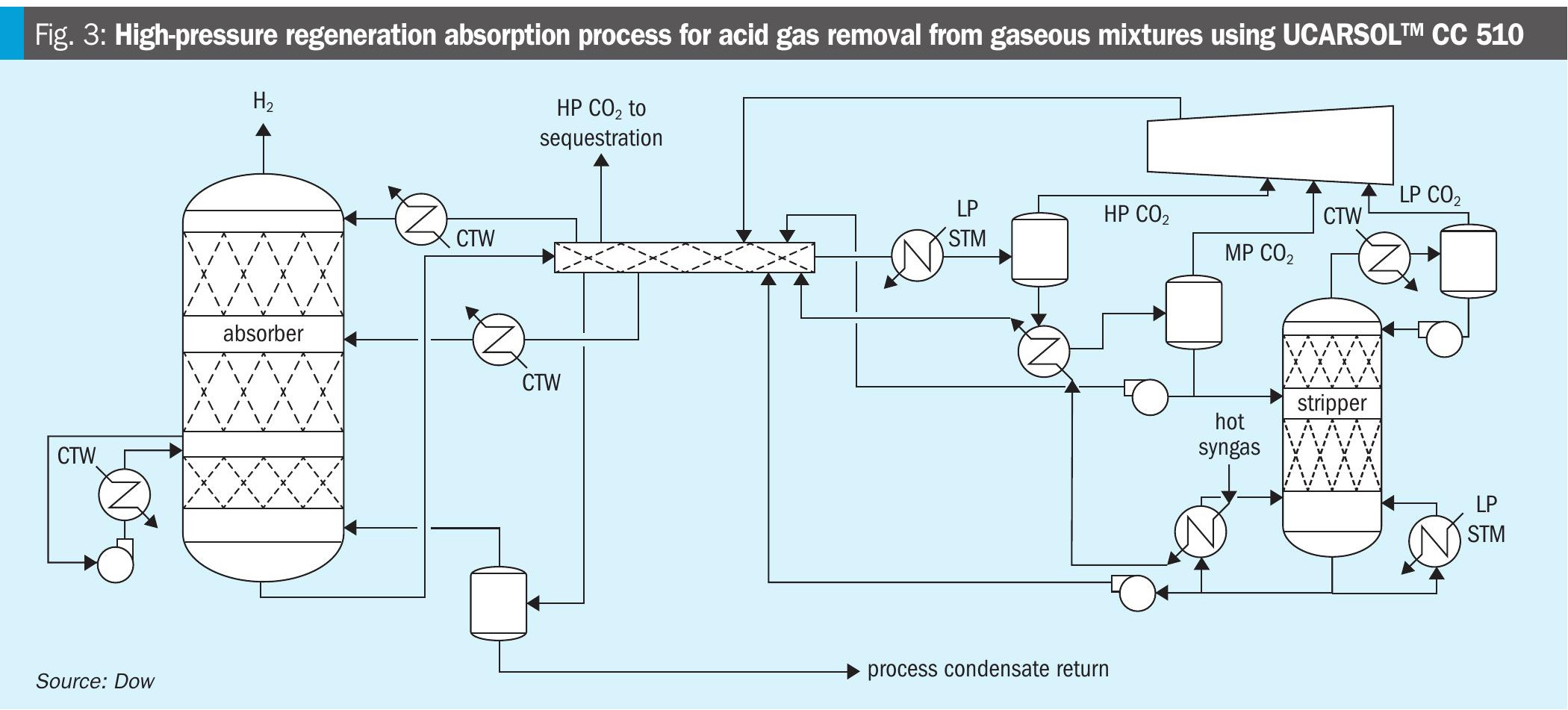
The solvent, UCARSOL™ CC 510, is a crucial element of the HPR process. It is formulated to maximise the amount of CO2 delivered from the HP and MP flashes, to minimise steam consumption, and to enable operation of the LP-regenerator at a pressure to eliminate the lowest stage of compression present in the conventional one-stage and two-stage processes previously discussed. It is important to note that the solvent is based on commercialised chemistries dating back decades and is not new to CO2 removal applications. Furthermore, the operating conditions of the HPR process are within the known operating window of the solvent, and increased thermal degradation due to the temperature and loadings of the flashes is expected to be economically manageable.
The heat exchange network is a second crucial element of the HPR process. Its key feature is heat integration of the rich solvent with at least three streams: the lean solvent, the semi-lean solvent, and the shifted syngas. There may be multiple points of heat exchange with the shifted syngas, and it is also possible to incorporate compression discharge heat and/or overheads heat into the heat exchange network. Prior to entering the heat exchange network, the shifted syngas is used to supply heat to the LP regenerator reboiler.
The HPR process shown in Fig. 3 is a two-stage process and thus incorporates a semi-lean stream to minimise steam consumption like the conventional two-stage process. A key benefit of the HPR process over the conventional process is the delivery of CO2 at conditions to reduce compression power and capital. The heat integration design features also enable considerable reduction in solvent circulation rate compared to the conventional two-stage design, reducing capital of the HPR amine unit in addition to the compression savings.
It is important to note that the additional heat extracted from the shifted syngas does not necessarily come at the expense of heat recovery in other parts of the overall hydrogen facility (e.g., boiler feedwater preheating). The additional heat used by the HPR process is heat that is sometimes wasted by conventional systems, in some instances being thrown away in a cooler prior to feeding the shifted syngas to the amine unit.
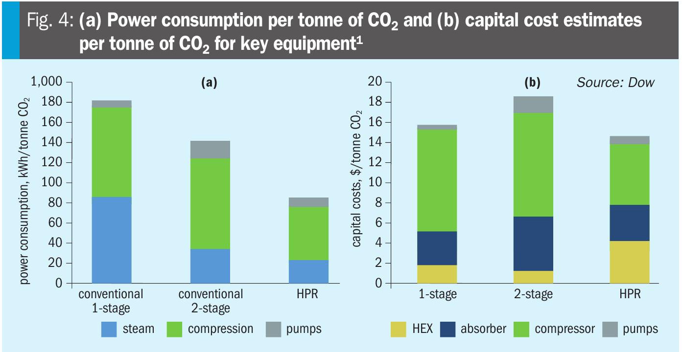
A technical comparison of solvent-based carbon capture options for blue hydrogen applications was performed for conventional processes as well as the HPR process. The results show that the HPR process achieves the lowest operational cost of all processes considered under the assumptions of the case study. It is further shown that the increased exchanger cost required to achieve the results offered by the HPR process are more than offset by the reduction in compression capital and absorber capital, leading to lower capital costs than the conventional processes (Fig. 4).
The HPR process presents a technically advanced pathway for reducing carbon capture costs in blue hydrogen applications by improving regeneration efficiency and minimising compression demand.
Reference