Nitrogen+Syngas 399 Jan-Feb 2026
23 January 2026
Urea technology showcase
UREA TECHNOLOGY
Urea technology showcase
Toyo Engineering Corporation, Stamicarbon and Saipem showcase their state-of-the-art urea technologies.
—————————————————————————————————————————————–
TOYO ENGINEERING CORPORATION
Advancement of ACES21-LP™: Low-Energy Concept
Since its establishment in 1961, Toyo Engineering Corporation (TOYO) has been a leading provider of urea process technology, consistently delivering reliable, efficient, and cost-effective solutions to the global fertilizer industry. In the late 1990s, TOYO introduced the ACES21™ process, which has since been implemented in 19 projects worldwide, including three of the largest single-train urea plants, each with a capacity of 4,000 t/d. In the early 2020s, TOYO further advanced its technology with the development of ACES21-LP™, currently recognised as the most energy-efficient and economically advantageous urea process.

Introduction to integrated technologies
This section provides a detailed description of the technologies integrated into the Low-Energy Concept ACES21-LP™ process.
ACES21-LP™
ACES21-LP™ is TOYO’s latest urea synthesis technology, featuring the lowest synthesis pressure of 136 barg and the highest CO2 conversion among modern commercial processes. TOYO was awarded the first project to apply ACES21-LP™ in 2023. The project involves building a 2,750 t/d urea plant for PT Pupuk Sriwidjaja Palembang (PUSRI-IIIB), designed for compatibility with both ACES21™ and ACES21-LP™. This project is currently in the construction stage and is progressing smoothly.
The key to realising ACES21-LP™ is the sophisticated use of DP28W™ , conventional duplex stainless steel, and 316L stainless steel in the synthesis section, combined with reduced passivation air.
The concept of ACES21-LP™ enhances features of the current ACES21™ process as follows:
- lowest synthesis pressure among commercial urea processes owing to the uniquely optimised synthesis conditions and reduced passivation air requirement;
- highest CO2 conversion among advanced modern urea processes;
- further energy savings (less opex) owing to less power requirements of the CO2 compressor, ammonia and carbamate pumps;
- lighter weight of HP equipment in synthesis section by 5-10% owing to the milder mechanical design conditions of the synthesis equipment.
Since the basic process scheme of the current ACES21™ process is retained in ACES21-LP™, the ACES21-LP™ concept can be easily applied to currently operating ACES21™ plants with minor modifications.
Development of the high heat recovery concentrator (HHRC)
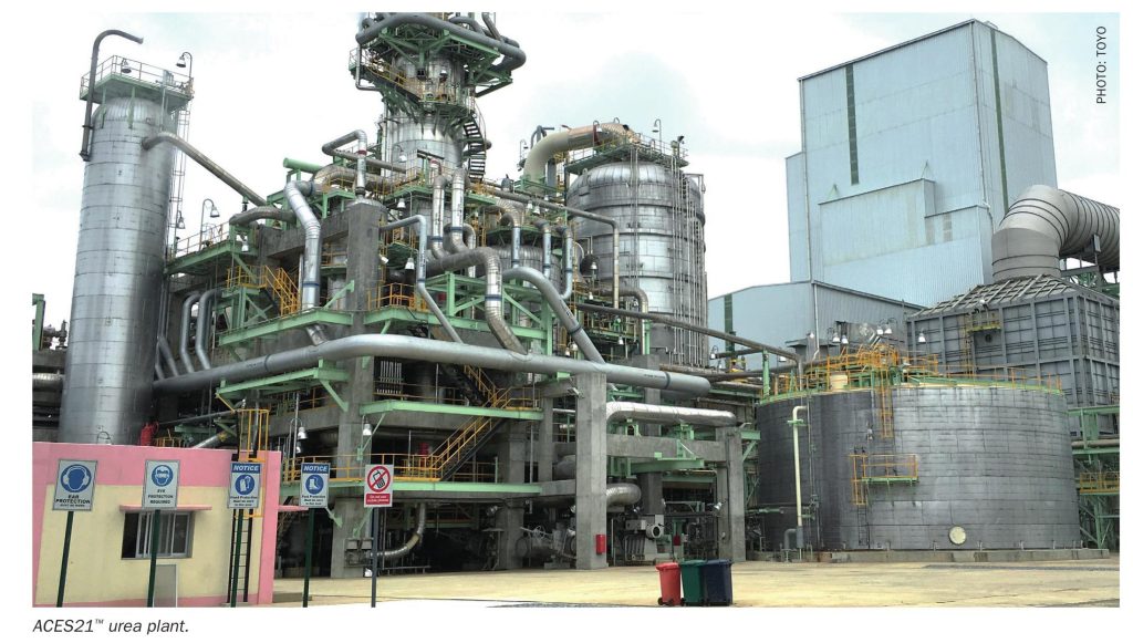
TOYO has recently developed a high heat recovery concentrator (HHRC). The HHRC is a high efficiency concentrator and has been incorporated into TOYO’s latest standard process. The HHRC operates with the shell side fully filled with liquid, functioning as a bubble column. The absorbent liquid is supplied through nozzles located at the lower part of the shell, while the top gas from the MP decomposer (MPD) is introduced via spargers also positioned at the bottom. Inside the shell, the gas and liquid are mixed, and most of the gas is absorbed into the liquid. The resulting mixed-phase flow, containing the remaining unabsorbed gas, is discharged from the top and sent to the MP absorber.
This process configuration is illustrated in Fig. 1. In the HHRC, the outer surface of the tubes is constantly in contact with liquid, which significantly enhances the heat transfer performance.
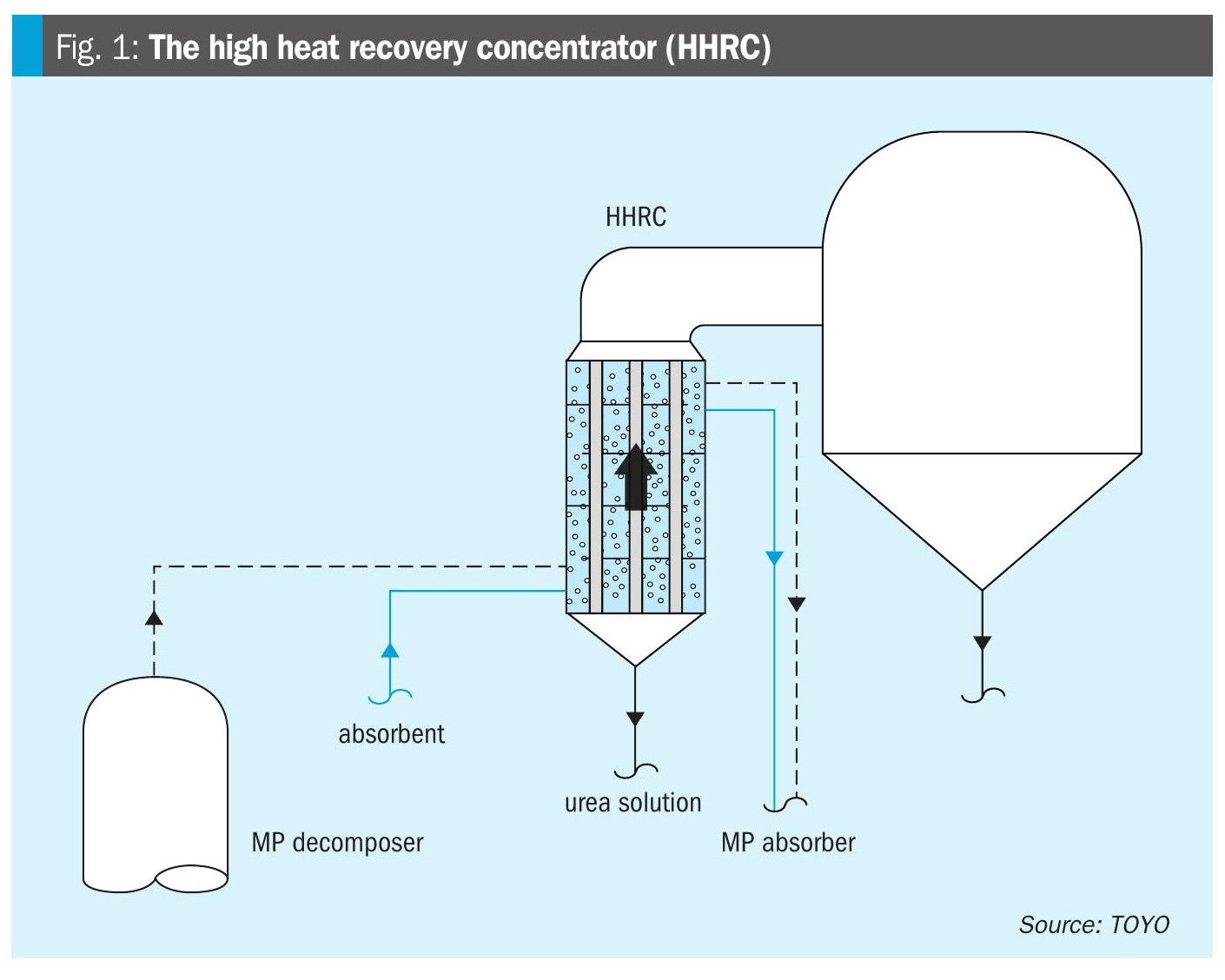
To further improve the performance of the HHRC, it is essential to ensure sufficient gas dispersion within the shell to promote effective gas-liquid interaction. Additionally, increasing the cross-flow velocity of the liquid across the heat exchanger tubes is crucial for achieving a high heat transfer rate.
To optimise the design, CFD analysis was conducted to evaluate the internal flow conditions of the HHRC. CFD analysis confirmed that gas was uniformly dispersed across all baffle surfaces within the shell, indicating excellent gas distribution. It also showed that high gas velocity was realised near the boundary of tube bundle. This flow induces liquid circulation, forming two to three distinct circulation flows – one toward the centre and others toward the periphery, as shown in the image on the left of Fig. 2. These circulation flows lead to a high crossflow velocity. This enhanced crossflow velocity contributes to improved heat transfer rate, allowing for a reduction of required heat transfer area by approximately 40%.
It is also possible to replace the conventional evaporator in existing plants with the HHRC, for energy saving and/or upgrading of the plants.
Compared to the conventional evaporator, the HHRC offers the following advantages:
- significant improvement in tube surface wetting and enhanced gas-liquid interaction;
- improved heat transfer performance, enabling a reduction in required heat transfer area and more compact equipment design;
- suppression of biuret formation by reducing the heat transfer area;
- simplified equipment configuration and reduced operating costs.
A project adopting the HHRC is already underway, and commissioning of the plant is expected in 2027.
Direct integration of LP decomposition and process condensate treatment
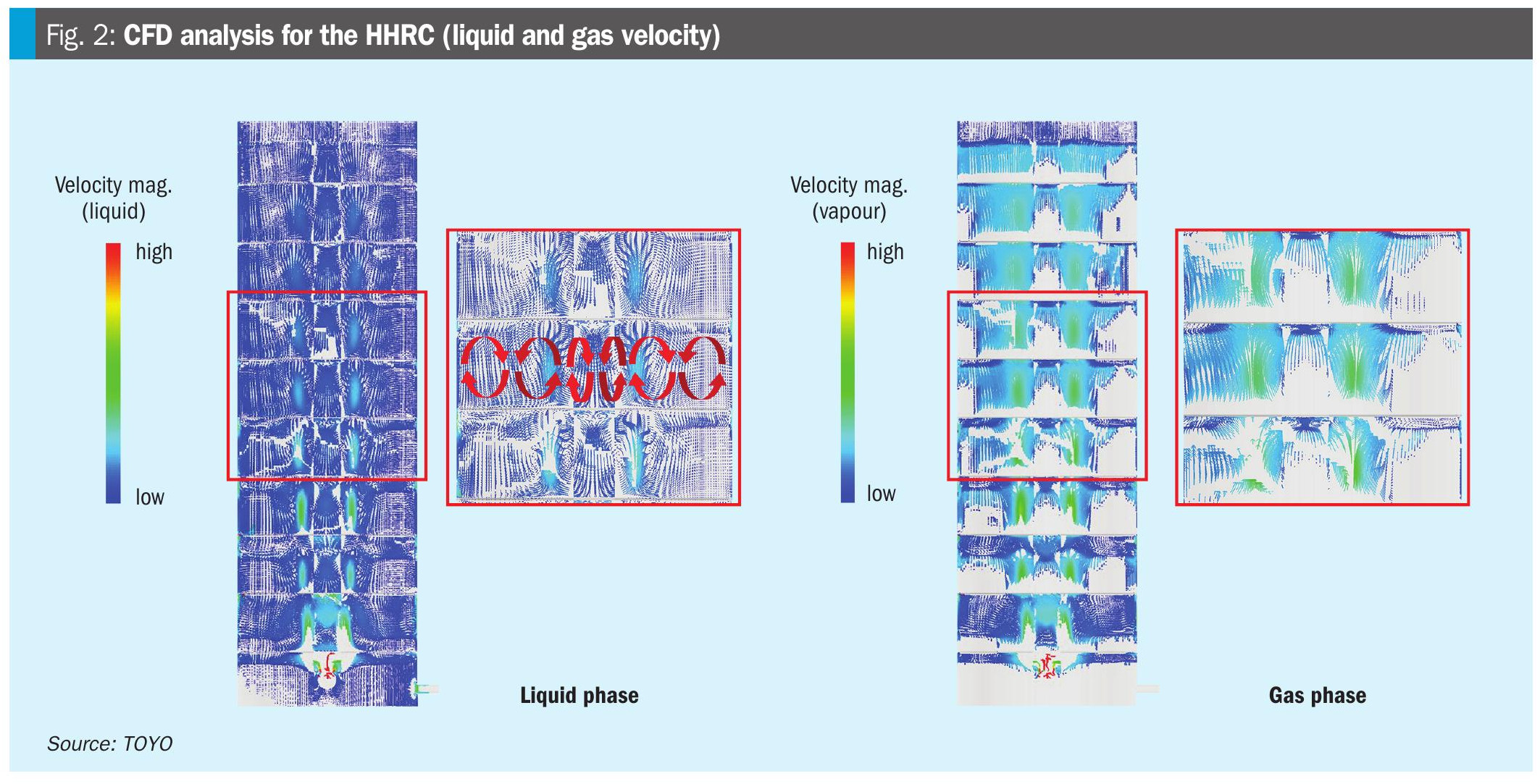
The process condensate stripper (PCS) is employed to remove NH3 and CO2 from the process condensate via steam stripping, thereby reducing the NH3 concentration in the condensate to a level suitable for discharge outside for urea plants. The stripping gas discharged from the top of the PCS contains not only steam but also the NH3 and CO2 removed during this step. This gas must be recovered and returned to the synthesis section to minimise raw material losses.
In certain processes, the gas is condensed using cooling water in a dedicated overhead condenser prior to recovery. However, this approach is inefficient because it requires cooling a large quantity of steam – the major component of the top gas – with cooling water. Moreover, installing additional equipment such as heat exchangers introduces pressure losses, necessitating operation of the stripper at elevated pressure to return the gas to the recovery section without auxiliary power. In general, lower operating pressure enhances stripping efficiency by facilitating the removal of residual components from the liquid phase; thus, additional equipment is undesirable from this perspective.
In TOYO’s process, the top gas from the PCS is directly introduced into the LP decomposer (LPD) as shown in Fig. 3. This configuration eliminates the need for heat exchangers and avoids associated pressure losses. The top gas is effectively utilised as a heat source and provides approximately 50% of the heat duty required in the LPD, allowing the steam input to the LPD to be reduced by about half.
Total integrated process based on “Low-Energy Concept”
Process description
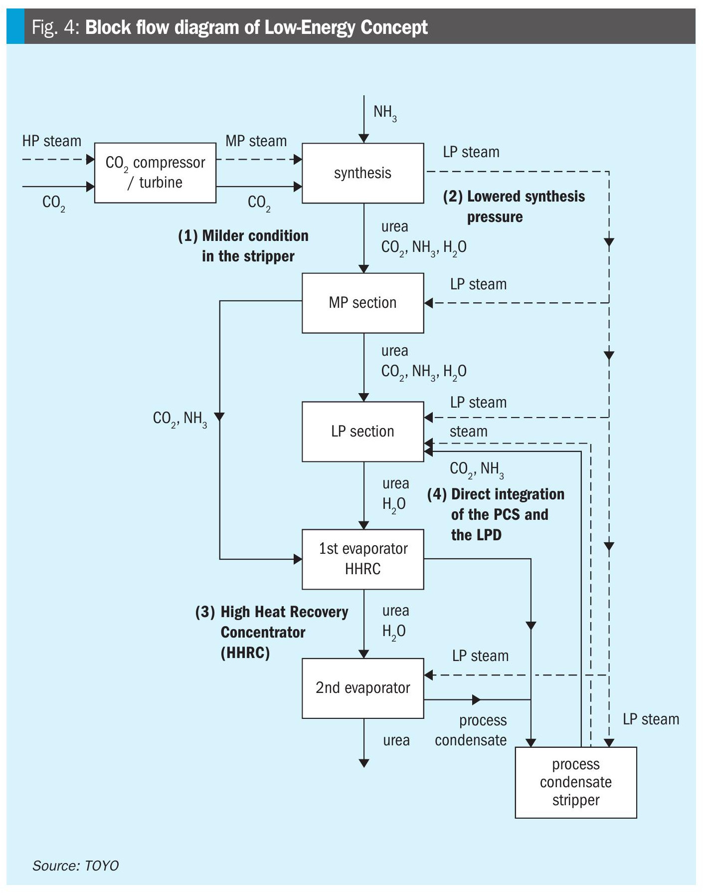
The Low-Energy Concept ACES21-LP™ process is realised through the combination of the following four key elements:
- milder condition in the stripper;
- lowered synthesis pressure;
- adoption of a newly developed HHRC;
- direct heat integration between the process condensate treatment and the LP decomposition.
A block flow diagram illustrating the integration effects is presented in Fig. 4. The specific impact of each element is discussed in detail below.
Milder condition in the stripper
In the Low-Energy Concept ACES21-LP™ process, stripping in the stripper is carried out under milder conditions. This enables the extraction steam from the CO2 compressor turbine to be supplied at a lower pressure. Consequently, the recoverable enthalpy within the turbine increases and the enthalpy of this steam is effectively recovered by the latest high-efficiency CO2 compressor and turbine, thereby decreasing the demand for high-pressure steam in the steam turbine.
Lowered synthesis pressure
Lowering the synthesis loop pressure enhances stripping efficiency in the stripper. By combining lowered synthesis pressure with milder condition stripping, HP steam consumption can be further minimised, while the carbamate concentration at the stripper outlet is controlled to an optimal balance for effective energy integration with the downstream sections.
As discussed, lowering the synthesis pressure also contributes to reducing the power consumption of HP rotating machines such as the CO2 compressor, and the ammonia and carbamate feed pumps. Moreover, it decreases equipment costs by lighter weight of HP equipment in the synthesis section by 5-10% owing to the milder mechanical design conditions of the synthesis equipment.
Adoption of newly developed HHRC
The residual carbamate in the stripper bottom liquid, which is optimised through milder stripping conditions and lowering the synthesis pressure, is decomposed in the MPD, and the resulting gas is directed to the HHRC. As described, this concentrator enables more efficient contact and absorption between the MPD top gas and the absorbent liquid compared with conventional evaporators, while effectively transferring the condensation heat to the tube side.
Consequently, the condensation heat (reaction heat to form ammonium carbamate) of the MPD top gas is efficiently recovered, allowing the urea solution to be concentrated to a higher level than in the conventional design. This improvement decreases the size of equipment and reduces steam consumption by approximately 40% in subsequent evaporator stages.
Direct integration of process condensate treatment and LP decomposition
Direct integration of process condensate treatment and the LPD reduces the LP steam consumption by approximately 50% in the LPD. LPD bottom effluent urea solution containing additional condensed water is sufficiently concentrated to a high level by the HHRC without need of any additional steam.
This process strategically integrates the aforementioned four innovative and proven technologies and optimises the operating conditions to overcome individual limitations, thereby achieving a substantial reduction in overall steam consumption.
Overall process performance
Operating variables are selected to maximise the integrated effect of the four key elements described.
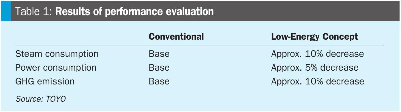
Under the above conditions, steam consumption and power consumption can be reduced by approximately 10% and by 5% respectively, and resulting greenhouse gas (GHG) emissions can be reduced by approximately 10%.
Conclusion
TOYO’s latest Low-Energy Concept ACES21-LP™ process is realised through the strategic integration of innovative and proven technologies. This process achieves significant reductions in energy consumption compared to the conventional design, resulting in substantial opex savings while contributing to a more sustainable urea industry.
Building on decades of expertise and continuous innovation, TOYO will continue to deliver solutions that address the environmental and economic demands of the urea industry.
——————————————————————————————————————————————-
STAMICARBON
From efficient urea melt production to large-scale granulation
The urea industry is increasingly shaped by the need for higher efficiency under conditions of rising costs associated with feedstock, energy consumption, and emissions. For producers, maintaining competitiveness requires maximising conversion efficiency while reducing operating costs. The global fertilizer market continues to favour large-scale production units, where economies of scale enable lower capital investment and operational costs while also reducing emissions intensity.
While efficient urea melt production is a requirement for such plants, downstream processing plays an equally critical role. Granulation remains one of the most effective methods for producing mechanically robust urea granules that can withstand bulk handling, long-distance transport, and extended storage. When integrated with high-efficiency synthesis technology, granulation allows producers to fully realise the benefits of large single-train urea plants without compromising product quality or environmental performance.
This article follows the value chain from efficient urea melt production to large-scale granulation and examines how continuous improvement and digital support contribute to operational reliability at increasing plant capacities.
Ultra-Low Energy
As the world market leader in urea technology, Stamicarbon, the nitrogen technology licensor of NEXTCHEM (MAIRE Group), continually develops solutions to extend plant lifetime, reduce emissions, and lower energy consumption. Stamicarbon is recognised for pioneering urea technologies, including the invention of the CO2 stripping process in the 1960s, which has since been continuously optimised for industrial application.
The most recent breakthrough in this development is the Ultra-Low Energy (ULE) design. This technology significantly improves the energy efficiency of urea production by allowing the heat supplied in the form of steam to be used three times instead of twice (Fig. 1).
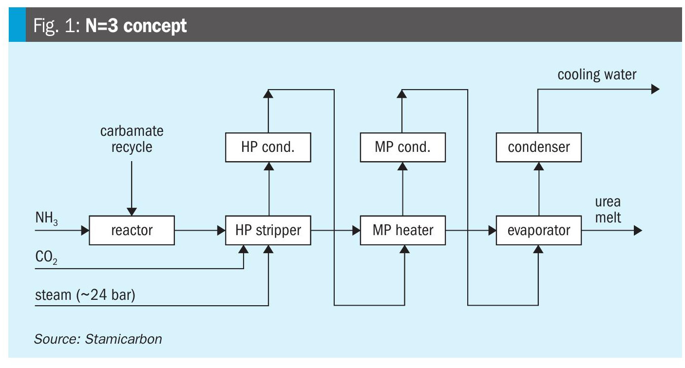
The key technological feature enabling these savings is the medium-pressure recirculation section, which allows carbamate to be flashed at medium pressure and reheated using the heat of reaction and condensation. The reheated carbamate is then reused for heat recovery, particularly for evaporation duties.
As a result, steam consumption can be reduced by up to 40%, while cooling water consumption is reduced by approximately 16% compared with conventional CO2 stripping processes. The design achieves the industry benchmark for steam consumption of less than 560 kg per tonne of urea, compared with approximately 870 kg/t for traditional CO2 stripping plants.
To date, the technology has been applied in ten projects worldwide. Seven operational plants with nameplate capacities ranging from 1,600 t/d to 3,850 t/d have demonstrated the designed energy performance under industrial operating conditions.
A most recent project awarded in China involves a single-train urea melt plant with a capacity of 2,700 t/d based on the Ultra-Low Energy design. The plant is designed to combine high-capacity production with reduced energy consumption, reflecting the continued market demand for large-scale, energy-efficient urea melt plants.
Based on Stamicarbon’s experience in new plant design, the Ultra-Low Energy design can also be applied to revamps of existing urea production, including non-Stamicarbon designed plants.
Granulation process
Large-scale urea melt production can be complemented by a downstream granulation process capable of handling large outputs while maintaining consistent product quality. Stamicarbon has extensive experience in designing urea granulation plants. This started with the first large-scale grass-roots granulation plant commissioned in Egypt in 2006. This plant was later successfully revamped to operate at a higher capacity.
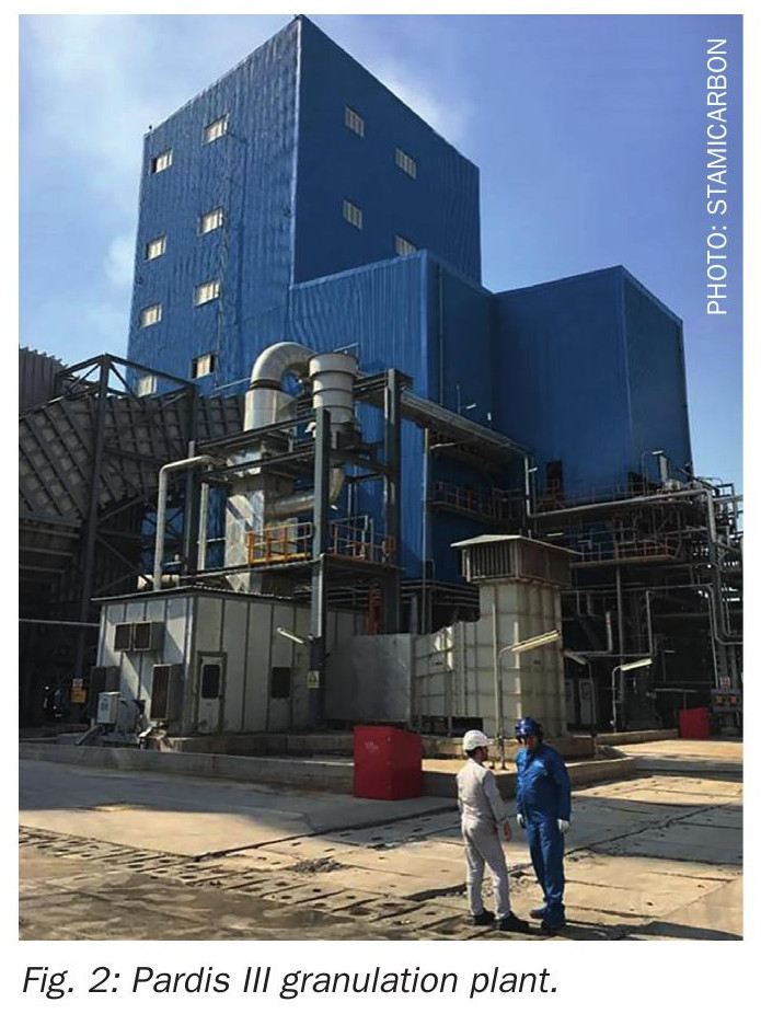
The largest operating granulation plant based on the Stamicarbon granulation design is the Pardis III plant in Iran (Fig. 2), with a nameplate capacity of 3,250 t/d. Contracted in 2011 and started up in 2018, the plant is capable of operating at 110% of nameplate capacity with a turndown ratio of 60%. The granulation unit is integrated with a fertilizer-grade urea plant based on Stamicarbon’s Pool Condenser design. Despite challenging climatic conditions, the plant has demonstrated reliable operation, achieving on-stream times exceeding two months during periods of extreme summer heat.
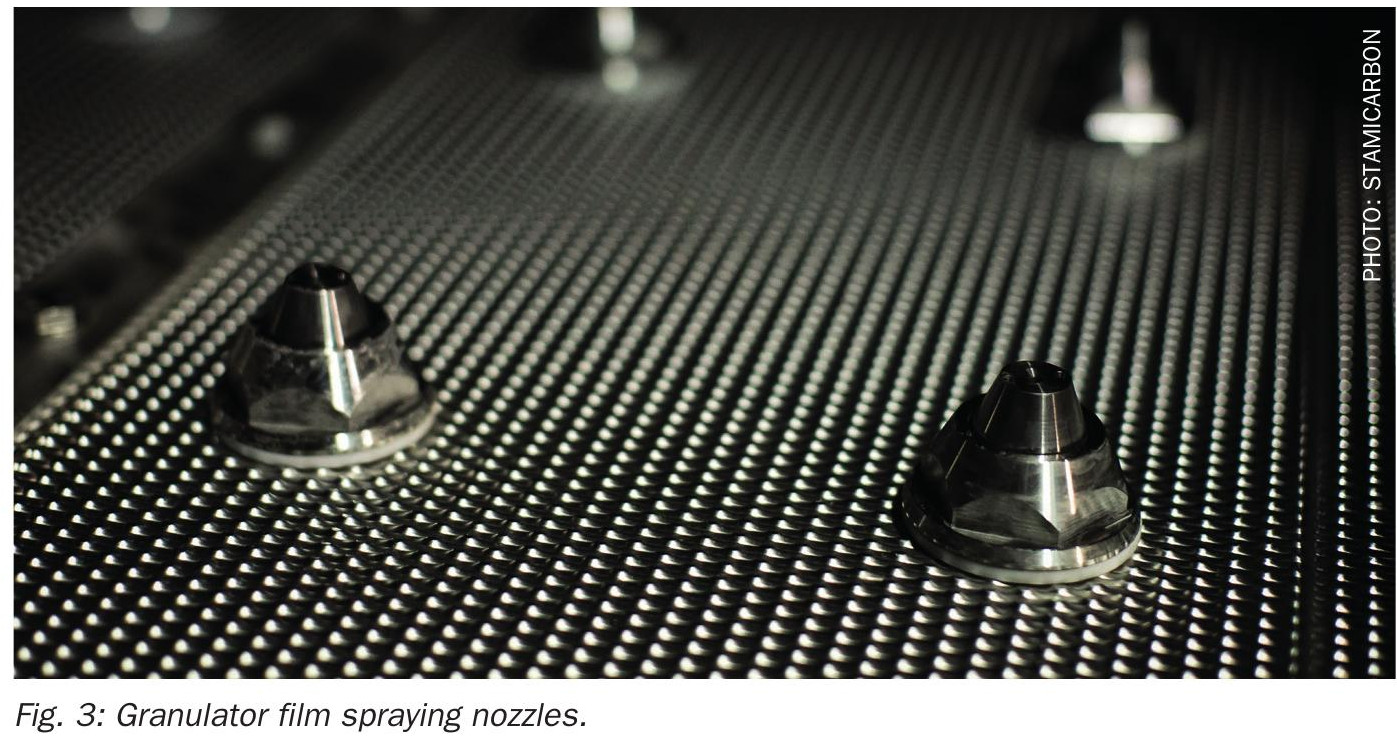
In the original Stamicarbon urea fluid-bed granulation process, urea melt with a concentration of approximately 98.5 wt-% is distributed by proprietary film-spraying nozzles (Fig. 3). Granule seeds are coated with thin layers of urea melt until the required product size is achieved. This process is characterised by low operating costs, reduced formaldehyde content in the final product, and limited dust formation. In practice, reference granulation plants have demonstrated long running times between the cleaning cycles, averaging over 90 days and reaching a record of 190 days.
Since the first implementation, nearly 20 Stamicarbon granulation plants of various capacities have been licensed, designed, and brought into operation.
Continuous improvement
In 2008, Stamicarbon introduced its optimised granulation design. This design features a simplified process layout (Fig. 4) with fewer equipment items, resulting in lower capital investment and reduced operating costs while maintaining product quality and high on-stream times.
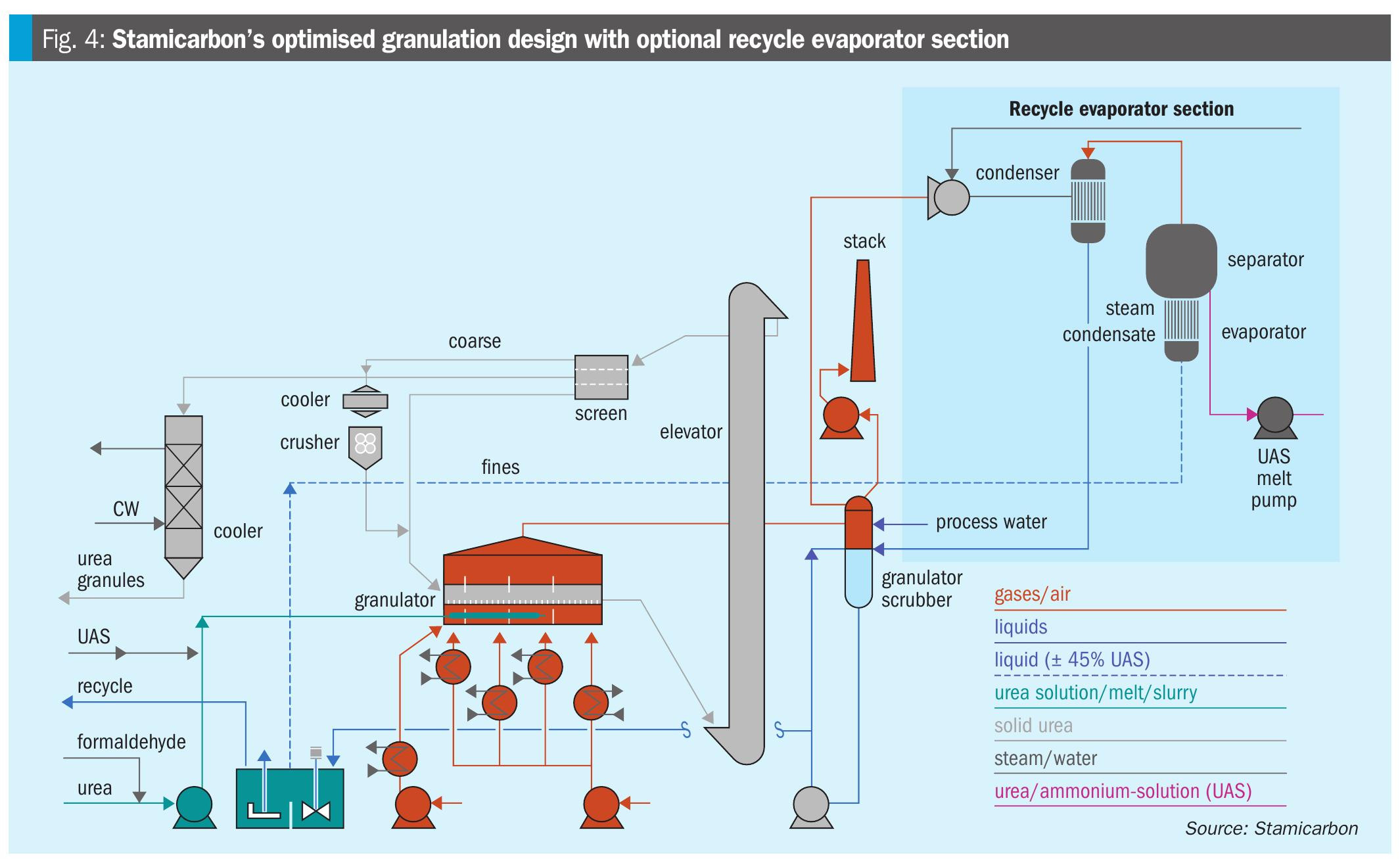
In this configuration, urea melt is fed to the granulator in the same way as in the conventional design, while one of the main differences lies in the final compartment, where the granulated product is cooled to a lower temperature. After passing the lump screen, the product is conveyed via a bucket elevator to the classification system. From there, the solid product flows by gravity through the main screens. Coarse product is fed to the crusher after cooling to approximately 70°C, while crushed material and fines are recycled to the first compartment of the granulator as seed material.
An on-specification product is cooled to storage temperature in a solids-flow cooler using cooling water rather than cooling air. Dust-laden air from the granulator, coarse cooler, and all de-dusting points is collected and treated in a single granulator scrubber.
The elimination of two major fluidisation fans significantly reduces electrical power consumption. The fluid-bed granulator cooler has been omitted by extending the cooling zone within the granulator, while the fluid-bed product cooler has been replaced by a solids-flow cooler. Associated scrubbers, pumps, and fans have also been eliminated.
A water injection system installed downstream of the fluidisation air fan reduces the required flow of cooling air. Fine water droplets evaporate along the air path to the granulator, lowering the air temperature. This feature is particularly beneficial during hot ambient conditions when operating above nameplate capacity.
The reduction in equipment results in a smaller plant footprint and lower capital expenditure. Additional savings are realised in transportation, construction, insurance, and land use, while reduced equipment also leads to lower maintenance requirements.
Reducing emissions
During the crystallisation of urea melt in the granulator, ammonia present in the melt is released and may be emitted to the atmosphere. Stamicarbon’s granulation process incorporates acidic scrubbing to capture this ammonia efficiently. Following dust removal, sulphuric or nitric acid is injected into a circulating aqueous solution that contacts the ammonia-laden air, forming an ammonium salt and reducing ammonia emissions in the exhaust gas.
The resulting ammonium salt solution can be sent outside battery limits or, when sulphuric acid is used, incorporated into the final product. In this way, no disposal streams are released to the atmosphere.
A technical challenge arises from the high water content of the scrubbing solution, which contains approximately 55 wt-% water, compared with the low water content of urea melt fed to the granulator. To manage this, a dedicated evaporation step is used to concentrate the recycled urea ammonium sulphate (UAS) solution before it is reintroduced into the granulator. The sulphur content in the final product remains low, typically around 0.05 to 0.1 wt-% S, allowing the granules to be marketed as standard urea.
In response to increasing agronomic demand for sulphur, Stamicarbon has developed a modular process for producing granulated urea enriched with higher levels of ammonium sulphate. Existing granulation plants can be retrofitted for this application with limited modifications and the installation of additional equipment.
Scaling up
In recent decades, urea granulation projects with capacities exceeding 3,000 t/d have become increasingly common. Such plants have demonstrated their ability to meet growing production and availability requirements.
Stamicarbon evaluated further scale-up while maintaining proven design principles and product quality. This assessment showed that a single-line configuration offers advantages over a dual-line configuration of equivalent total capacity, including an estimated reduction of approximately 30% in total capital investment.
In 2019, Stamicarbon licensed its first single-line 4,000 t/d urea granulation plant, equipped with a MicroMist Venturi™ (MMV) scrubber to meet environmental requirements. In 2022 and 2023, two other 4,000 t/d plants were licensed for a customer in Africa.
Based on experience gained from scaling conventional designs and operational and manufacturing expertise, the optimised granulation design can be extended to a single-line capacity of 5,000 t/d.
Digital support
As plant capacities increase and process integration becomes more complex, digital tools play an increasingly important role in supporting safe and efficient operation. One operational advantage of the Ultra-Low Energy design is the presence of the medium-pressure recirculation section, which reduces process disturbances typically encountered in conventional CO2 stripping plants. However, to further enhance operational reliability, operator training remains essential.
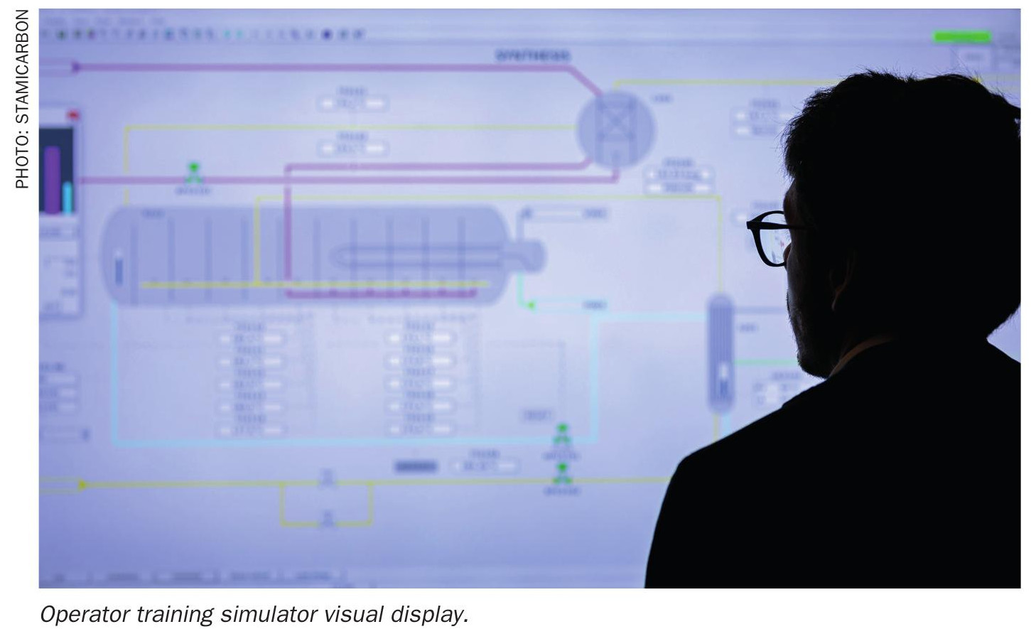
As an example, the urea plant at Jinjiang Xinlianxin, with a capacity of 2,334 t/d, was the first facility to apply Ultra-Low Energy technology. Prior to start-up in February 2021, operating personnel were trained using Stamicarbon’s Technology Training Simulator (TTS), part of the NX STAMI™ Digital portfolio, ensuring a complete understanding of plant behaviour under various scenarios. The startup was completed smoothly on the first attempt. The plant initially operated at reduced load and was subsequently ramped up to above 100% capacity within the first week after feedstock availability was secured. The start-up took place during COVID-19 lockdowns in China, with remote training via TTS enabling commissioning without on-site support.
Conclusion
Stamicarbon provides a complete range of technologies, products, and services that cover the entire urea value chain. Technologies for urea synthesis, including the Pool Condenser, Pool Reactor, and Ultra-Low Energy designs, enable improved plant efficiency, reduced operating and maintenance costs, and lower emissions. This is complemented by a range of finishing solutions, including proven state-of-the-art fluid-bed granulation technology, as well as technologies for producing urea prills, pastilles, and liquid fertilizers. Stamicarbon also offers digital solutions that support stable operation, high availability, and optimised energy performance in urea plants.
By leveraging extensive experience in nitrogen technology and collaborating with sister companies within NEXTCHEM (MAIRE Group), Stamicarbon can deliver a complete value chain of technological solutions for sustainable fertilizer and fuel production.
—————————————————————————————————————————————
SAIPEM
Saipem’s Snamprogetti Urea Technology improving execution strategy and overall efficiency
Saipem’s Snamprogetti™ Urea Technology has been licensed for more than 140 units, of which 115 are currently in operation. With a long history of innovations to reduce both capex and opex, such as the introduction of the carbamate ejector and the horizontal layout, Saipem now offers a well-proven design that provides operational flexibility, especially for high-capacity plants.
Below are the most recent improvements, which address major project challenges in execution strategy and overall efficiency. These developments leverage Saipem’s experience both as a licensor of urea technology and as an EPC contractor.
Modularisation
Saipem has further optimised engineering solutions to enable full modularisation of each unit within the ammonia–urea complex. The approach uses compact layout modules that cluster equipment to minimize plot occupancy and shorten pipe routes, bringing process advantages while maintaining operability and reliability.
A representative example is the CERES project, currently under execution. It represents a significant milestone in the ammonia and urea industry as it is the first Topsoe Ammonia SynCOR™ plant in an advanced stage of construction and the first to feature a very high degree of modularisation for both ammonia and urea plants. The facility will produce 2.3 million tonnes per annum (t/a) of high-quality urea. Saipem’s proprietary Snamprogetti™ Urea Technology was selected for the synthesis and purification of the urea solution fed to the granulation section.
The process scheme applied to the project is robust and efficient and retains the technology’s standard configuration without modifications, ensuring state-of-the-art energy recoveries and consumption. The horizontal layout and plot plan – developed by Saipem in its dual role as licensor and contractor to facilitate construction and maintenance – are proven in several reference plants.
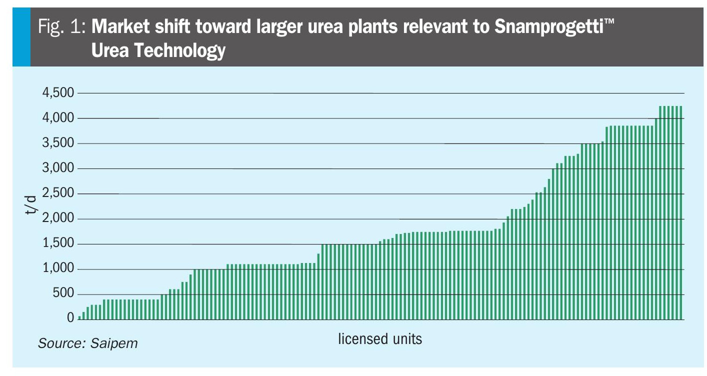
As demonstrated by the CERES project, modularisation is effective even for high-capacity urea plants. Recent installations using Snamprogetti™ Urea Technology reflect the market’s trend toward ever larger capacities. The graph in Fig. 1 shows the progressive increase in nominal capacity for Snamprogetti™ Urea Technology and it is representative of a general trend for all urea technologies.
Higher efficiencies in ammonia– urea integrated plants
Saipem has continuously improved the energy efficiency of its licensed plants through several measures, including additional energy-recovery systems, the introduction of the double carbamate condenser scheme, and, more recently, the SuperCups™, which enhance mixing within the reactor to increase conversion and reduce energy demand for decomposition in the downstream sections.
A key contribution from Saipem is its ability to integrate the urea unit with the ammonia unit and utilities – this integration has the largest effect on overall natural gas consumption.
Notable features from recent EPC projects include:
- electrification of most drivers;
- use of high-efficiency integral-gear compressor technology (for example, in CO2 service);
- combined-cycle power generation integrated with excess steam from the ammonia plant;
- integration of renewable power, where available, to minimise energy input and associated CO2 emissions across the complex.
SATURN31™ — The new superduplex material for HP urea sections
SATURN31™ is a new superduplex material developed jointly by Tubacex and Saipem for use in the high-pressure section of urea plants. The development objective was to balance superior corrosion resistance with manufacturability and constructability.
Reference corrosion performance in urea high-pressure environments is well established from experience with 25/22/2 Cr/Ni/Mo and AISI 316L UG. The goal for SATURN31™ was to outperform these reference materials, achieving lower corrosion rates even in oxygen-free conditions, thereby allowing the elimination of a dedicated passivation air compressor at the bottom of the urea stripper.
Being a superduplex material it was important to ensure smooth manufacturability, excellent weldability, and good machinability. The material’s improved mechanical properties also enable weight reductions and lower opex.
Several numerical simulations were carried out at the outset of the development to define possible chemical compositions, which were also tested in laboratory-scale heats; the composition finally selected was then tested in industrial-scale heats.
The new highly alloyed superduplex, SATURN31™, has high chromium and nitrogen contents and moderate additions of molybdenum, tungsten, and cobalt. The well balanced chemical composition and an optimised solution-annealing treatment produces a homogeneous distribution of austenite and ferrite bands, free from intermetallic phases and precipitates. This combination of alloying elements delivers excellent resistance to urea solutions with or without oxygen, and high resistance to localised corrosion (pitting and crevice corrosion).
Urea stripper ferrules were the first industrial application of SATURN31™. The material will next be used as a liner and for other internals in high-pressure equipment such as SuperCups™. Following ASME codification, SATURN31™ will also be used to manufacture pressure-resistant components for equipment and piping, opening the way to design and manufacture the entire high-pressure equipment in SATURN31™.
A particularly innovative development under way is producing the new generation of SuperCups™ using SATURN31™ via additive-manufacturing techniques.
Small-scale urea plants
Leveraging its extensive licensing, engineering, and construction experience, Saipem now offers a skid-mounted urea plant concept targeting capacities up to 100 t/d. The concept preserves the classic five-section process scheme to retain advantages such as operational flexibility and low environmental impact.
To optimise capex versus efficiency, particularly where energy is supplied from renewable sources, the design reduces some energy-recovery items compared with a traditional scheme. Additional optimisations include using single pumps (with spare units kept in storage) to minimise footprint. These layout optimisations are applicable to both skid-mounted and stick-built constructions.
Although these small-scale plants can be provided with conventional finishing such as prilling or granulation, pastillation is often more effective, based on capacity and layout (skid mounting/modularisation considerations. Such plants are suitable for technical production (for example, standalone DEF units) and for valorising waste streams (e.g., CO2), and extra production (e.g, NH3), or exploiting renewable energy.
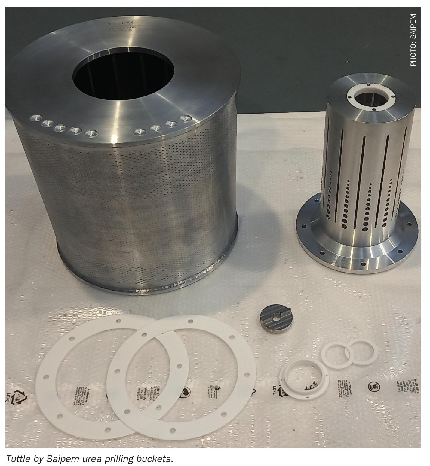
Tuttle by Saipem urea prilling buckets
In 2018, Saipem acquired Tuttle’s prilling-bucket technology and began marketing the product under the name Tuttle by Saipem. Between the early 1970s and 2018, Tuttle delivered over 500 prilling buckets worldwide.
After the acquisition, Saipem enhanced the technology to improve product quality (granulometry) and reduce dust. Improvements focused on both design and manufacturing. Extensive computer simulations – validated against historical data – were used to define design parameters for the desired product quality. On the manufacturing side, production moved from largely manual drilling to computer numerical control (CNC) machining.
Since the acquisition, Saipem has manufactured and delivered more than 50 buckets worldwide for new plants and replacements.
A recent development is a design and manufacturing procedure for the production of buckets for microprills. Microprills differ substantially from standard prills: typical diameters range from 0.42 mm to 2 mm, with an average of about 1 mm. Historically, the smallest prilling bucket was designed for an average diameter of 1.6 mm, so producing microprills required new design, manufacturing, and quality-control solutions.
Key challenges and solutions for the microprill bucket included:
- operating at rotational speeds more than 1.5 times higher than standard prill buckets;
- drilling hole diameters less than half those used for standard prills;
- implementing stepwise drilling and redrilling with intermediate cleaning to preserve drill-bit integrity;
- introducing enhanced inspection techniques, using concentrated light in a darkroom, to address the small hole size and challenging inspection angles.
These measures ensure reliable production of microprills while maintaining manufacturing quality and product consistency.
——————————————————————————————————————————————