Nitrogen+Syngas 392 Nov-Dec 2024
30 November 2024
Conversion into hybrid ammonia plants
DECARBONISATION
Conversion into hybrid ammonia plants
One challenge of a green revamp by stepwise injection of green hydrogen into existing ammonia/urea complexes is to cover the nitrogen demand for the ammonia synthesis while stepwise reducing the front-end load, usually by applying a cost-intensive air separation unit (ASU). thyssenkrupp Uhde GmbH has developed an advantageous concept whereby, instead of an ASU, the nitrogen gap is closed by the introduction of pretreated reformer flue gas back into the ammonia process, with the side effect to also enhance CO2 production.
The fertilizer industry is at the start of a feedstock transition towards low-carbon or even carbon-free (green) production, which will have considerable impact on plant owners. A “green revamp” by stepwise injection of green hydrogen into an existing ammonia/urea complex is a promising way to reduce the carbon footprint of the assets and provide new business opportunities. However, this feedstock transition requires consideration of certain boundary conditions.
Green hydrogen injection into an existing ammonia plant can be generally utilised for two revamp possibilities:
- replacement of natural gas by maintaining the production capacity (i.e. decarbonisation);
- additional ammonia production.
In both cases, where one operation mode does not necessarily rule out the other, the conventional natural gas-based (grey) plant will be converted into a hybrid (grey/ green) ammonia production and the green hydrogen injection can be increased stepwise to increase the green share of the production. Considering the demand in the market for sustainable fertilizers and/or green ammonia as an energy carrier, this conversion is the most viable and fast-track way compared to the construction of an entirely new plant.
The main subject of this article is the decarbonisation of the ammonia plant (i.e. natural gas replacement and reduction of carbon footprint) with the goal to realise the green revamp without major hardware modifications within the process plant, particularly by avoiding the need for an air separation unit. This is feasible by the careful check of certain boundary conditions.
Boundary conditions
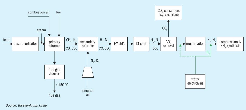
For the decarbonisation of the plant, the focus is mainly on the plant frontend (synthesis gas production) where the green hydrogen is usually injected upstream of the syngas compression as shown in Fig. 1.
Depending on the hydrogen profile, the application of intermediate hydrogen storage may be necessary, as the operational flexibility of the plant, especially of the reformer section, is limited. The required minimum size of the storage can be studied as a first step.
The tie-in point for the green hydrogen can be upstream of the syngas compressor or the methanation unit (to remove possible O2 traces in the green hydrogen stream). Since the green hydrogen is inert-free, there is already a positive impact on the syngas compression load and the ammonia synthesis.
For the replacement of natural gas and therefore for the load reduction of the front-end, the following three main boundary conditions were identified:
- Steam production/superheating: The heat recovery for steam production and pre-heating takes place mainly after the secondary reformer and in the flue gas channel. The high-pressure steam demand is nearly constant since the load of the major consumers like the syngas compressor and the CO2 compressor remains unchanged.
- N2 supply: Nitrogen is usually injected with the process air. The N2 demand remains unchanged since the production capacity will be maintained.
- CO2 supply: Carbon dioxide is separated from the syngas in the CO2 removal unit and in most cases there is an attached urea plant which requires a constant CO2 supply as feedstock. As a matter of fact, less natural gas feed leads to less CO2 production. In case of no CO2 consumers, this boundary condition remains unconsidered.
Increasing decarbonisation
Based on several decarbonisation projects, Table 1 shows the findings that could be detected by the stepwise increase of green hydrogen injection with respect to the above-mentioned boundary conditions.
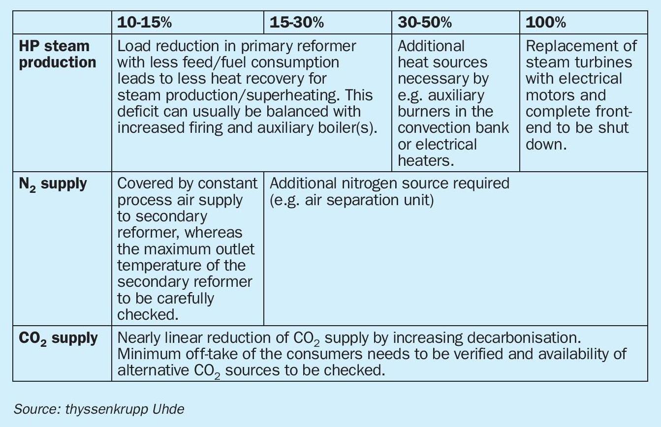
Looking at Table 1, decarbonisation rates of >30% cannot be handled without hardware modifications and the deficits in N2 and CO2 supply become more severe. Additionally, the required amount of green hydrogen will likely be the bigger issue looking at the limited availability for the time being. For instance, the decarbonisation of a 1,200 t/d ammonia plant by 30% requires an electrolysis capacity of 140-150 MW.
However, the decarbonisation of the fertilizer complex < 30% is more realistic and is manageable without major hardware modifications in the process plant and only the N2 and CO2 supply needs to be addressed.
Focusing on the N2 supply, an ASU is usually applied as a necessary source which always represents the main cost driver of the green revamp. As an alternative, thyssenkrupp Uhde has developed a concept to close the nitrogen gap by utilising the reformer flue gas as described in the next section.
Nitrogen supply by flue gas recovery
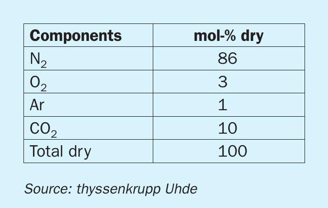
The reformer off-gas which is normally released into the atmosphere has the following typical composition as shown in Table 2.
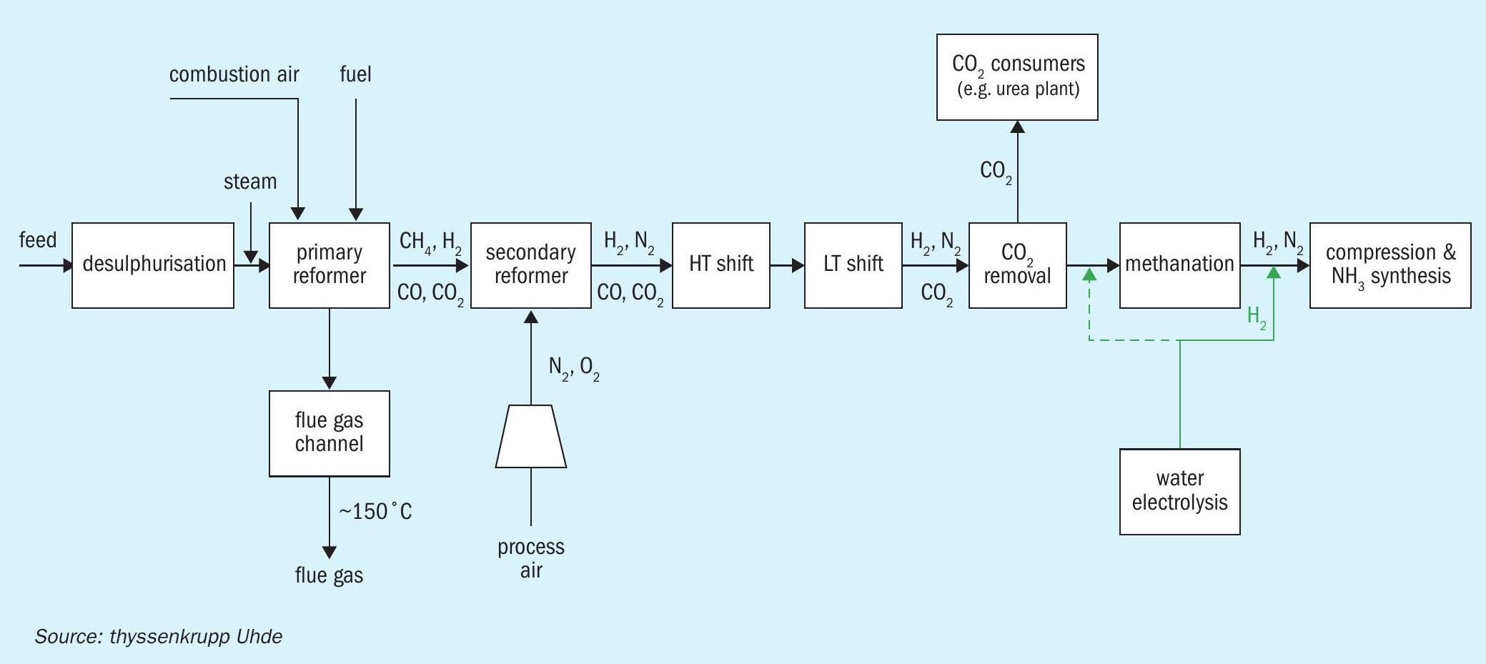
The concept is to utilise the high nitrogen content of the reformer flue gas and introduce a part of it together with the process air into the ammonia process. As shown in Fig. 2, a flue gas conditioning/treatment step is necessary to remove the impurities to allowable levels before entering the process air compressor.
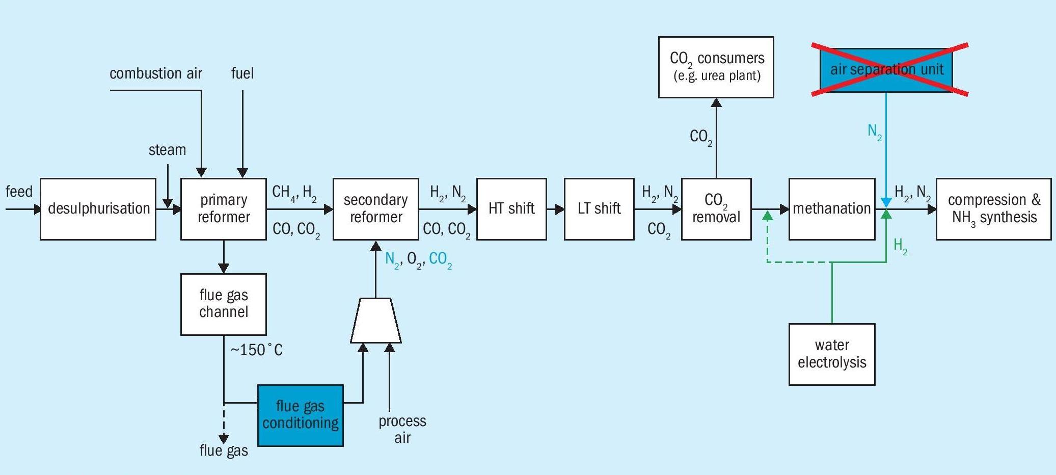
The flue gas needs to be cooled and cleaned accordingly, so as not to harm the catalysts in the process and the downstream equipment, where the main focus is the removal of the SOx traces in the flue gas stream. N2O or NOx traces in the stream are not critical from a catalyst point of view as these components will break down into N2 and H2O in the reducing environment of the secondary reformer. Furthermore, the water content in the flue gas stream will be significantly reduced by condensation, which is beneficial for the process air compressor load and, after appropriate treatment, this water can be used as demin or cooling water.
There is a further important benefit of this concept because the flue gas is also an additional CO2 source which enters the process and is washed out in the existing CO2 removal unit. Hence, the inevitable CO2 deficit is also significantly reduced.
A wet scrubber process with a caustic solution as neutraliser is one possible technology for flue gas conditioning/ treatment. It is well-referenced and widely used in other industries with even more severe applications.
Comparison of flue gas recovery vs. ASU for N2 supply
The pros and cons of flue gas recovery versus an air separation unit for nitrogen supply is summarised in Table 3.
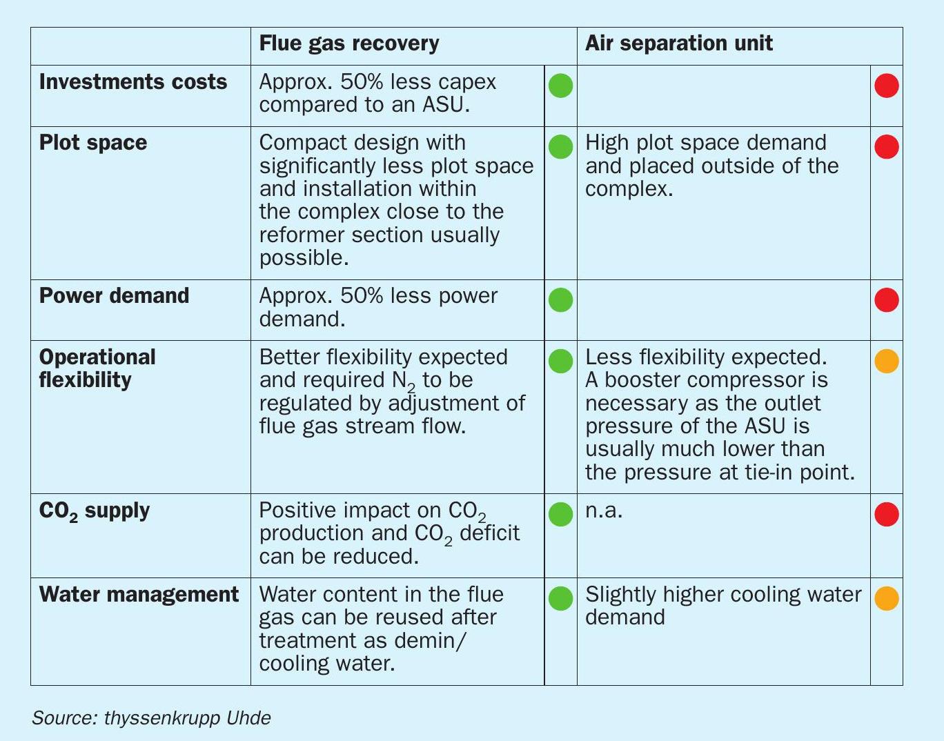
For their implementation, both concepts are add-on solutions which don’t require long plant shutdowns. The erection works can be carried out mostly during running operations and only the tie-ins have to be done during a scheduled shutdown.
Summary
The decarbonisation (i.e. replacement of natural gas) of an ammonia plant is a complex exercise where the N2 deficit and the CO2 deficit (in case of required feedstock for attached plants, e.g., urea plant) are the limiting factors for decarbonisation rates up to ≈30%. thyssenkrupp Uhde has developed a cost-effective concept to address these deficits by utilising the reformer off-gas and feeding it into the process after appropriate cleaning.
Flue gas cleaning/conditioning is widely used in other industries and can be considered as proven technology. This concept has overwhelming advantages compared to nitrogen supply from an expensive air separation unit and flue gas recovery has the further advantage of also reducing the inevitable CO2 deficit.