Nitrogen+Syngas 377 May-Jun 2022

31 May 2022
Handling leaks in urea plants: part 1
Leaks in the high-pressure synthesis section of a urea plant may lead to catastrophic consequences. In 2017, building on an incident database set up by UreaKnowHow.com, AmmoniaKnowHow.com and UreaKnowHow.com introduced FIORDA, the Fertilizer Industry Operational Risk Database, a global open source risk register for ammonia and urea plants.
A surprising conclusion from this database is that most safety risks in a urea plant lead to the sudden release of a toxic cloud of ammonia. Early detection of a leak is important as minor and small leaks can be easily contained.
But what action is required after a leak has been detected? Are all leaks critical? Can a flange connection be retightened, can a temporary clamp solve the problem, or does the plant need to be shut down?
This series of articles explains why leaks in the high-pressure synthesis section of a urea plant are dangerous, what happens when there is a leak, possible consequences and prevention and mitigation measures.
Why are leaks in the HP synthesis section so critical?
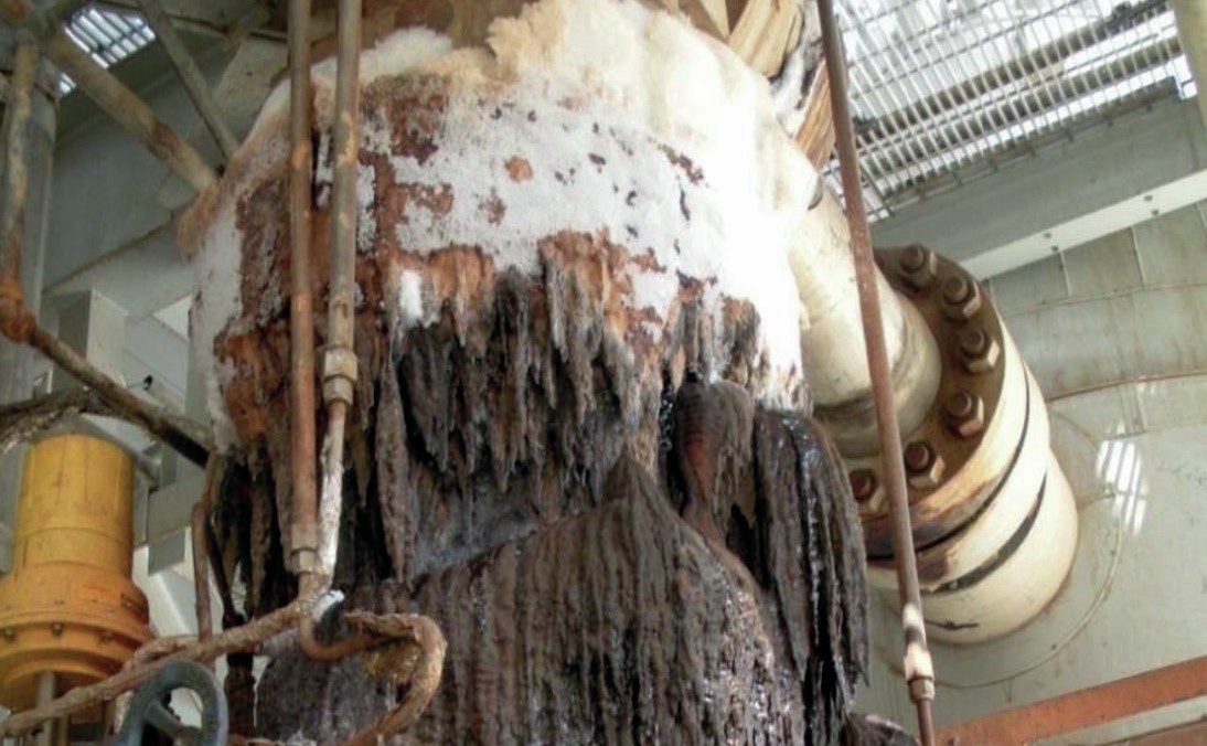
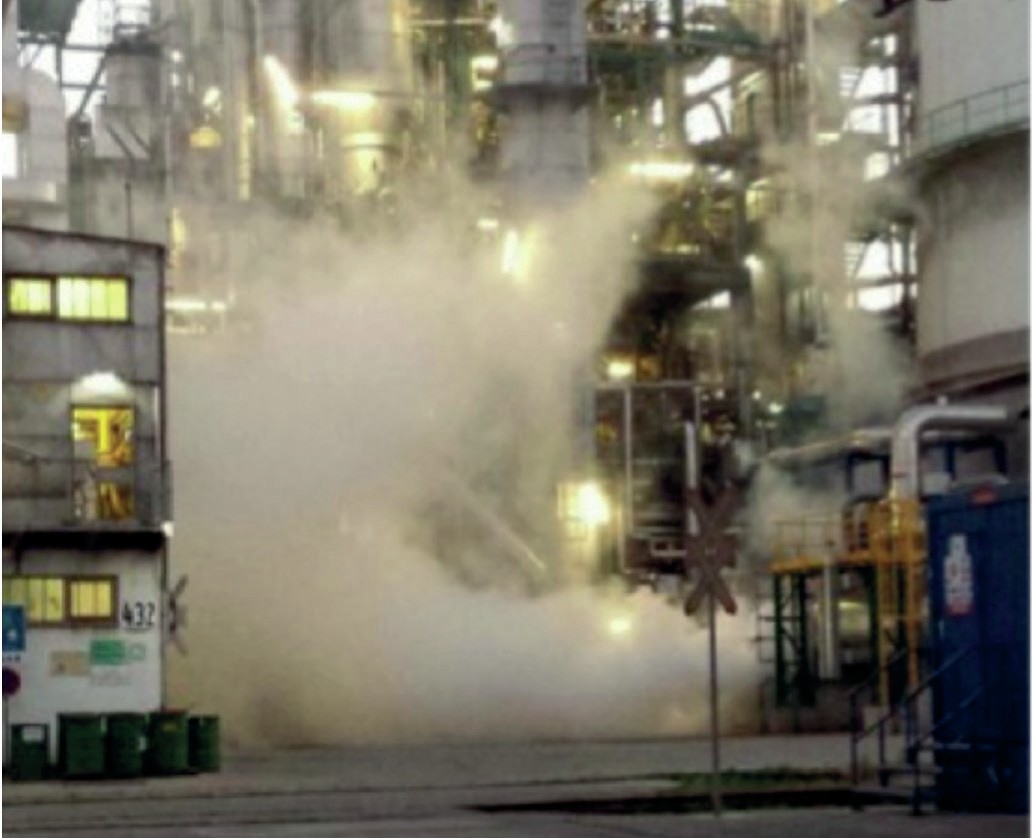
The pictures in Fig. 1 show several examples of leaks in urea plants.
Leaks can easily occur in urea plants due to corrosion and sealing challenges.
Corrosion challenges
In a urea plant one must continuously take into account the risk of corrosion due to the presence of ammonium carbamate. At the relatively high temperatures, ammonium carbamate behaves like a strong Brönsted acid. Proper material selection of the equipment is important and the presence of a sufficient amount of oxygen is especially critical to keep the corrosion rates within certain limits (passive corrosion). Even when sufficient oxygen is present, there will always be some passive corrosion, in the order of 0.01-0.02 mm per year (0.0004-0.0008 inches/year). This means that wall thicknesses reduce slowly over time and finally leaks can occur. Where there is insufficient oxygen, for example, in crevices or dead ends or in condensing liquid in a gas phase, passive corrosion will turn into active corrosion with much higher corrosion rates occur, some 30-50 mm per year (1-2 inches per year).
Sealing challenges
Due to the corrosive medium only a limited number of special urea grade materials can be applied in a urea plant. This means that the required hardness difference between, for example, flanges and the lens ring is not easy to realise, because for a proper sealing the difference in hardness should be minimum 20 hV. In addition, selection of the type of seals is limited; a design with gaps or crevices cannot be used. Consequently, greater attention is required to obtain proper sealing.
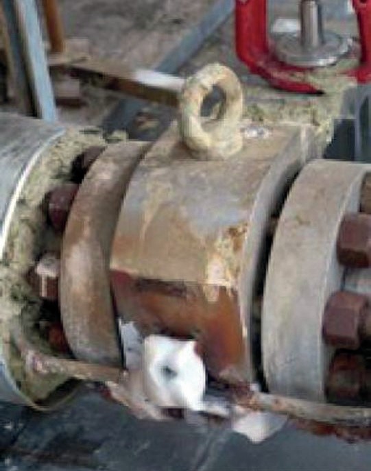
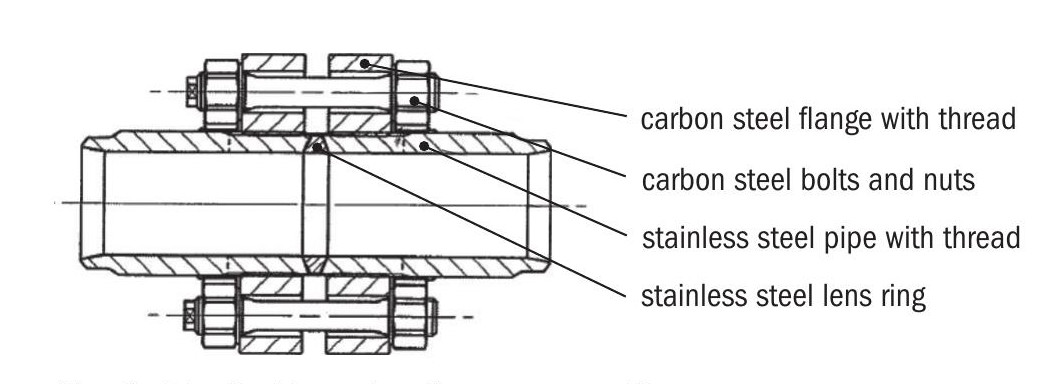
A lens ring joint with carbon steel threaded flanges and carbon steel nuts and bolts is often used in urea plants (see Fig. 2).
The shape of the lens ring is such that a line-shape sealing ring is created as indicated in Fig. 3.
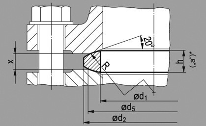
The big advantage of a line-shape sealing ring is that less force is required to create the seal. The sealing effect is achieved by elastic deformation of the surfaces which implies that applying the right bolt load is very important. Lens ring gaskets are in principle reusable, but in a urea plant it is not recommended to reuse a lens ring gasket. Lens ring gaskets are also sensitive to high bolt forces. With increasing loads, the lens ring gasket deforms and the shape changes, the radius becomes flatter and the contact surface between the lens ring gasket and flange increases (flat surface sealing), increasing the risk of crevice corrosion.
What happens when it leaks?
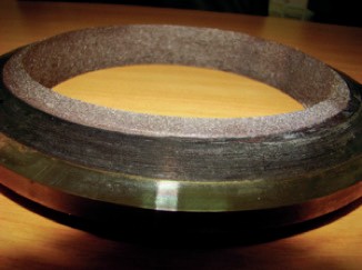
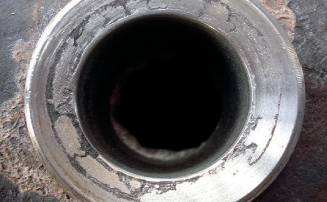
It is common knowledge that crevices should be avoided in the high-pressure synthesis sections of urea plants. In a crevice ammonium carbamate liquid enters, oxygen will be depleted and corrosion rates (active corrosion) increase leading to crevice corrosion and the flange connection will start to leak. Fig. 4 shows the result of crevice corrosion on a stainless steel flange face.
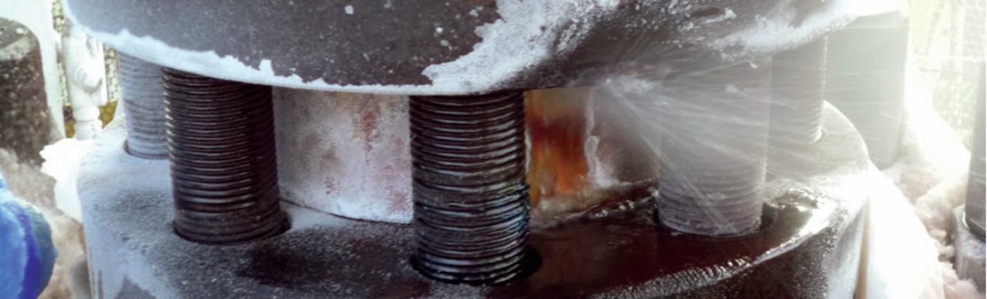
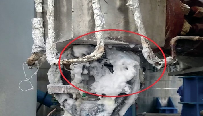
However, a crevice and/or a leak can occur in a lens ring flange connection due to several causes such as no proper alignment, insufficient torque on the bolts, too thin lens ring gaskets, lateral defects in the face of the lens ring or flange face, pipeline vibrations (reciprocating pumps, high pressure drops) or excessive stresses due to not proper piping design/installation. Fig. 5 shows a typical leak of a lens ring flange connection.
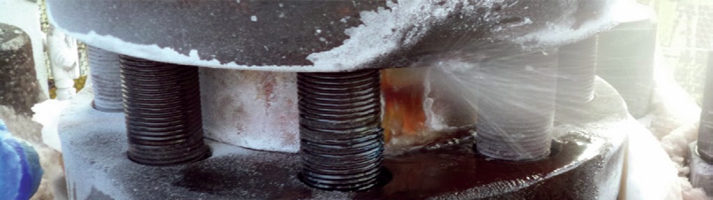
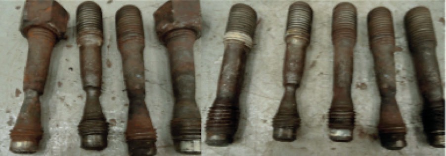
Typically, a leak cannot be stopped anymore because solids, which are formed during the flashing from high pressure to atmospheric pressure, will erode the leak path. Furthermore, the leaking ammonium carbamate is extremely corrosive for carbon steel parts like the threaded flanges, bolts and nuts as shown in Fig. 6.