Sulphur 391 Nov-Dec 2020
30 November 2020
New ways with oxygen enrichment technology
OXYGEN ENRICHMENT TECHNOLOGY
New ways with oxygen enrichment technology
New approaches and novel processing schemes employing oxygen enrichment in sulphur recovery units have been developed and commercialised. In this feature Siirtec Nigi, Linde, Blasch, Fluor and RATE report on their latest developments.
SIIRTEC NIGI
SplitOxy: a renewed approach to oxygen enrichment
Using oxygen-enriched air in the Claus process is recognised as one of the most effective ways to improve sulphur processing capacity. The objective of the enrichment process is to reduce the amount of inert gas involved in the Claus process by adding pure oxygen to atmospheric combustion air.
In fact, the main limitation to Claus unit capacity increase is the pressure drop across the plant. Therefore, capacity increase with oxygen-enriched air means that more acid gas feed can be sent to the Claus unit within the overall hydraulic capacity constraints.
Oxygen enrichment not only meets the purpose of increasing sulphur recovery unit (SRU) throughput, but it also comes with a number of benefits for SRU operation and can be provided in a new unit or as a retrofit to existing units.
When revamping an existing Claus unit with oxygen enrichment, the maximum enrichment level that is expected to be achieved, often originated from the expected required extra capacity, dictates the corresponding design approach.
A novel oxygen enrichment technology application in the medium-high oxygen enrichment level, the Siirtec Nigi’s SplitOxy technology, has been studied and recently supplied to revamp the SRU-IV in Ecopetrol’s Gerencia Refinería Barrancabermeja in Colombia.
The SplitOxy technology by Siirtec Nigi was recently presented as part of the technical agenda in the Virtual Sulphur + Sulphuric Acid 2020 conference.
The role of temperature
There are various levels of oxygen enrichment that can be applied to a Claus process. Most technologies, however, are grouped into the three categories shown in Table 1.
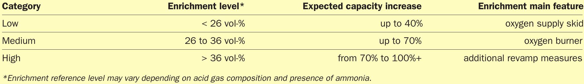
Whilst low/medium-level oxygen enrichment can, in theory and in practice, be achieved by virtually every sulphur recovery unit at minimum cost, at higher oxygen concentrations the reaction temperatures are likely to reach over 1,550°C with the potential to approach the limit of the refractory lining material of the Claus reaction furnace (1,700°C).
Depending mainly on the acid gas composition, the upper limit of oxygen enrichment level for SRUs in refinery applications (approx. 34-36 vol-%) has to be defined in order to keep the reaction furnace (RF) temperature below 1,550°C.
In addition, the waste heat boiler (WHB) and the sulphur condensers need to be checked to ensure they also have adequate heat transfer capabilities with oxygen enrichment operation.
One proven concept for implementing high-level oxygen enrichment is to inject into the Claus burner only a part of the oxygen required to achieve the Claus stoichiometry, whilst keeping the operating temperature of the reaction furnace well below the refractory limit. This is possible by adding oxygen in a stepwise manner, which allows for intermediate removal of reaction heat, thereby postponing part of the combustion to a secondary chamber located in the rear end of the WHB, where the gas temperature is still high enough for further H2 S conversion. This is the SplitOxy technology. 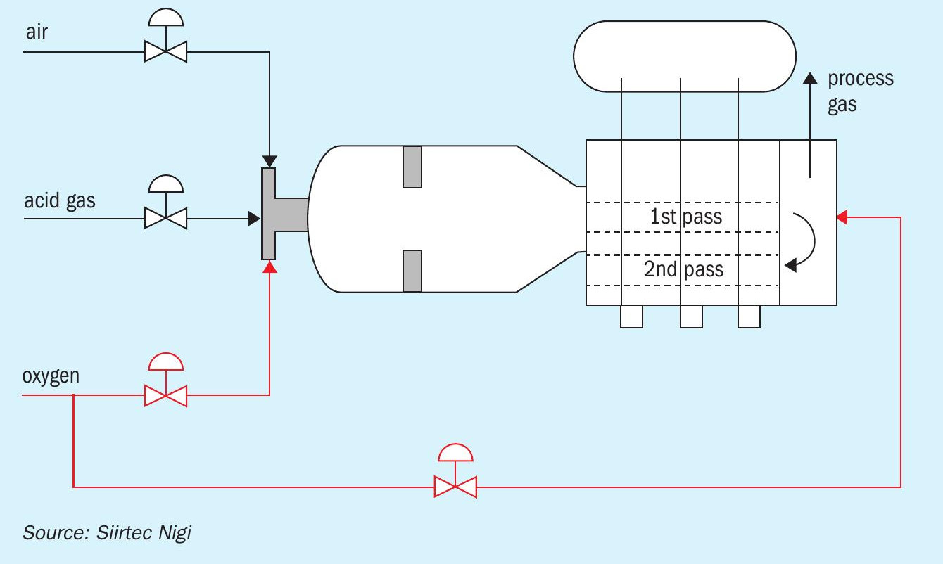
The SplitOxy technology
The concept is straightforward: the temperature limitation can be overcome by splitting the oxygen supply into two streams. The main oxygen stream is fed into the Claus burner while the slipstream is fed into the rear end of the WHB after intermediate removal of reaction heat (Fig. 1).
Significantly, there is no sulphur condenser between the WHB and the second reaction chamber. There is also no burner in the second reaction chamber. Effluent from second reaction chamber flows through the WHB second pass and then to the condensing passes and catalytic stages.
By design, under all operating conditions the gas exiting the WHB first pass and entering the second reaction chamber is substantially above the H2 S auto-ignition temperature.
Through process optimisation, it is possible to identify a fixed oxygen split ratio to be maintained in the entire operating range in order to limit the reaction furnace temperature within the desired envelope while enhancing the conversion efficiency.
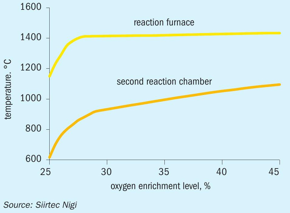
The temperatures in the reaction furnace and the second reaction chamber in the SplitOxy process for a typical rich refinery gas with significant ammonia presence are shown in Fig. 2, as overall oxygen concentration is increased from 25 to 45 vol-%.
At constant oxygen split ratio, the temperature in the reaction furnace is kept below the limit of 1,550°C regardless of the overall enrichment level; this arrangement allows the process control to be extremely safe and simple: only one parameter is controlled, the overall oxygen enrichment level, whilst operator intervention is limited to the optimum and safe operating window.
SRU revamp at Barrancabermeja refinery
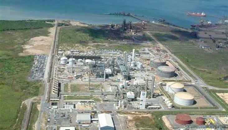
Before oxygen enrichment was used to increase capacity, the SRU-IV operating in the Ecopetrol Barrancabermeja refinery had a maximum throughput of 52 t/d of liquid sulphur. The unit was originally licensed in 2004 by Siirtec Nigi and built in 2007.
The unit consisted of a thermal stage (reaction furnace) followed by three catalytic stages. As common for smaller units, the waste heat boiler and three sulphur condensers were integrated into one piece of equipment.
The original SRU-IV was able to treat both acid gases coming from the amine regeneration unit (AAG) and from sour water stripper unit (SWSG), which contain both H2 S and ammonia.
The purpose of the revamp was to achieve the following targets:
- increase the total capacity to 90 t/d using atmospheric combustion air plus oxygen, with the flexibility to still operate with combustion air only at original capacity;
- improve operation to achieve a high service factor without decreasing overall sulphur recovery.
Additional project constraints included:
- minimising layout requirements to fit new equipment within the existing plot area;
- minimising capex.
Therefore, Siirtec Nigi’s approach to the design of the revamped SRU was based on two principles:
- minimising the impact on the existing plant by maintaining the original design gas flow throughput in the equipment downstream of the thermal stage;
- keeping the operating temperature of the reaction furnace at a reasonable level.
Among several alternatives, a solution based on the SplitOxy scheme was selected, with a target overall enrichment level of 36 vol-%, in order to meet project objectives and plant requirements.
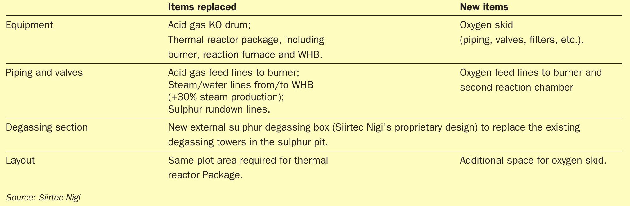
Table 2 summarises the results from assessing the existing facilities, in accordance with the revamp objectives.
Scope of the revamp – schedule
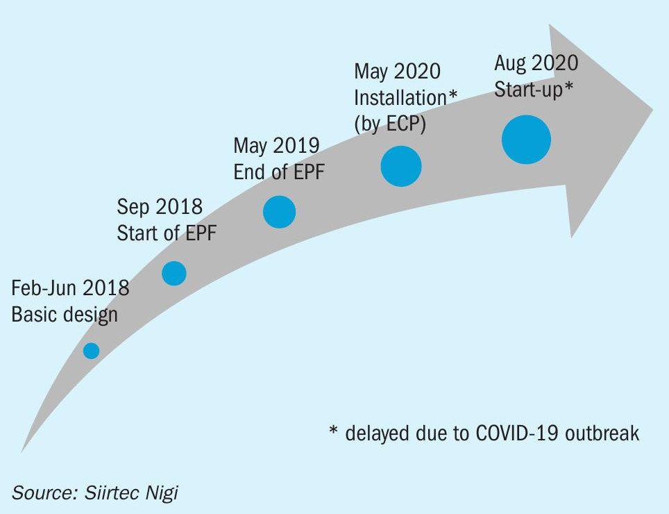
Siirtec Nigi’s key role in revamping the SRU-IV is shown in Fig. 3.
After the EPF phase (engineering, procurement and fabrication of SRU-IV critical equipment) Siirtec Nigi was also involved in the detailed engineering development, which started on December 2018, and the site services for the overall revamp activities (erection and dismantling).
The new equipment was successfully installed and started-up on August 2020 and has been continuously operating using oxygen since then.
Siirtec Nigi’s new thermal reactor package
A new thermal reactor package (including burner, reaction furnace and waste heat boiler) based on the Siirtec Nigi’s SplitOxy technology was designed to comply with the project requirements.
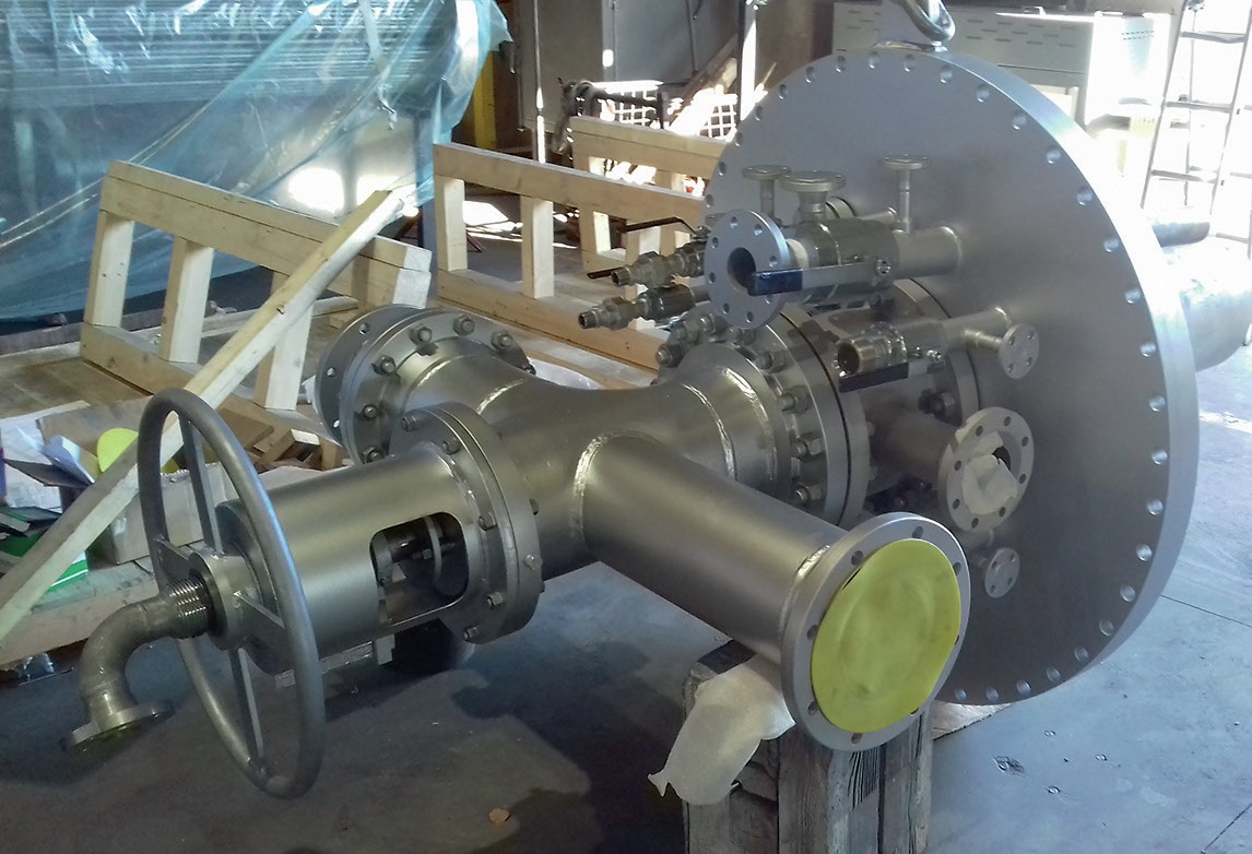
The reaction furnace is equipped with the advanced Siirtec Nigi oxygen enrichment burner (Fig. 4), which is an evolution of the oxygen burner for Claus units developed in early 2000s.
The acid gases are injected into the main burner in the same way as an air-based Claus burner. The oxygen is injected into dedicated ports surrounding the acid gas gun in order to achieve an oxygen concentration gradient – thus a temperature gradient – in the reaction furnace, mitigating the thermal stress on the refractory lining.
The compact burner design allows it to be fitted in the new reaction furnace without impacting its overall dimensions.
The new reaction furnace is a conventional two-zone thermal reactor with internal second zone gas distributor and quite similar to the original unit. It has been customised to fit with the new Siirtec Nigi’s oxygen burner and to ensure adequate refractory/ferrules design and selection to comply with the new process conditions.
In the revamped SRU, the new waste heat boiler is still provided as the first pass of a multi-function heat exchanger.
As already mentioned, in the SplitOxy process some of the oxygen is injected into the rear end of the WHB first pass, thus postponing part of the H2 S conversion to a colder, but still very active, zone.
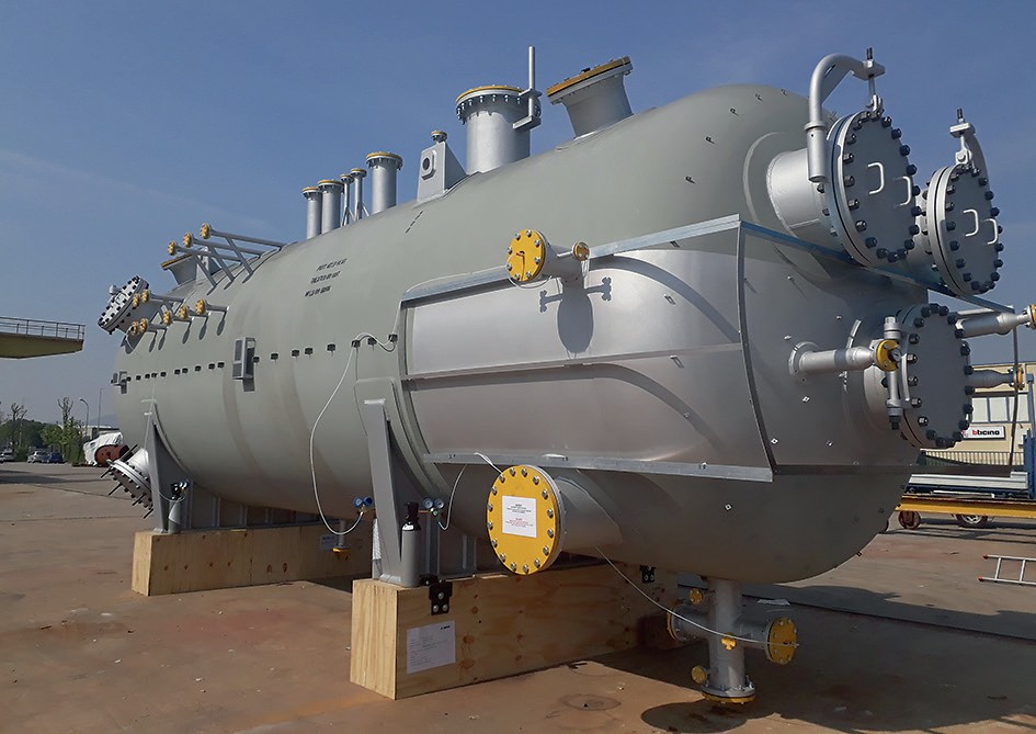
Rather than directing the hot gas from the WHB first pass to a separate reaction chamber, the rear channel of the new multi-pass waste heat boiler was designed to provide the right residence time and to become the second reaction chamber.
Compared to the original equipment, the new WHB features the same tube size, number and length. However, the layout of tubes and channels of the five passes has been modified to fit the new second reaction chamber (Fig. 5).
A dedicated burner is not required, as only oxygen lances are used to introduce oxygen into the second reaction chamber.
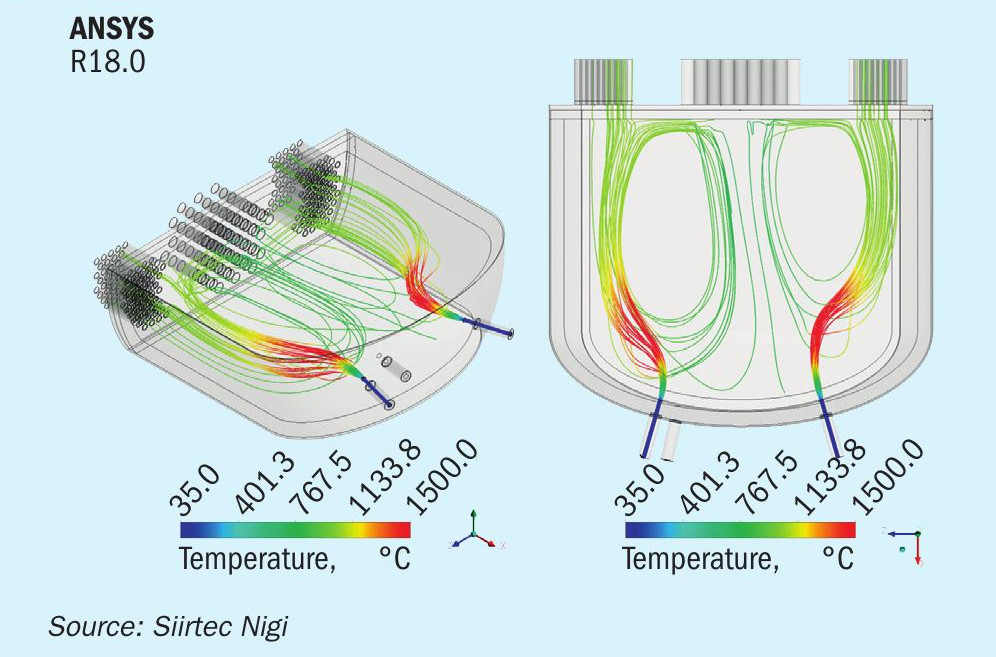
Computational fluid dynamic (CFD) modelling was used to support the design of the WHB second reaction chamber (Fig. 6), factoring in the number of oxygen lances and their diameter, length, position and orientation. The model was also used to validate the residence time in the chamber and the adequacy of refractory material selection.
A new (remote) start-up
After the basic design and EPF phases, Siirtec Nigi provided site assistance to the client for the following activities:
- operator training;
- supervision on dismantling and erection activity;
- pre-commissioning, commissioning and start-up technical assistance.
As both installation and commissioning were supposed to take place during plant turnaround, the initial schedule was set for March 2020.
While training sessions were held onschedule on February 2020 at Ecopetrol premises in Colombia, the supervision of dismantling and erection was only partially executed as the site activities, due to the Covid-19 outbreak, came to a sudden slowdown.
The global pandemic situation made it clear that a new approach to site assistance had to be developed.
Due to the Colombian safety rules and travel restrictions, Siirtec Nigi passed on the technical knowledge for the Ecopetrol’s team to safely and properly handle the remaining site works.
Installation and pre-commissioning activities were conducted by Ecopetrol at site during April-June 2020, while Europe was facing the Covid-19 lockdown.
In the commonly agreed path forward, Siirtec Nigi meanwhile prepared full stepby-step procedures for commissioning and start-up of critical equipment (such as the thermal reactor package, degassing box and oxygen supply skid), drawing attention to relevant operating and safety issues.
The start-up activities at site were then planned to be carried out by the refinery personnel under Siirtec Nigi’s remote live assistance on a daily basis.
Start-up of the revamped SRU-IV was finally scheduled for the end of July 2020, with a duration of approximately 16 days.
The hardware, software and people
The key persons involved in the start-up phase of the revamped SRU-IV were:
- Siirtec Nigi’s process specialist, located in Milan;
- Ecopetrol focal point for SRU start-up, located in Barrancabermeja.
Due to the difference in time zones, daily assistance was scheduled from 1 pm to 9 pm (CET). The schedule for meetings, communications and continuous remote assistance was adapted to engage the two teams from different time zones.
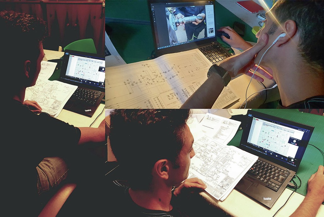
An online communication channel was set up to organise daily calls, briefing on previous day site activities and updates about project schedule.
Through this channel, the DCS historical trends of process variables, gas compositions and any other data were promptly made available to the Siirtec Nigi specialist (Fig. 7).
Dry-out and heating-up operations
By the time Siirtec Nigi joined the remote support activities on July 26, 2020, the SRU-IV was completing the commissioning activities and final checks before proceeding with reaction furnace dry-out and heating-up.
The dry-out was accomplished by burning fuel gas in the reaction furnace burner with excess of combustion air, as required to remove any moisture contained in the refractory after installation.
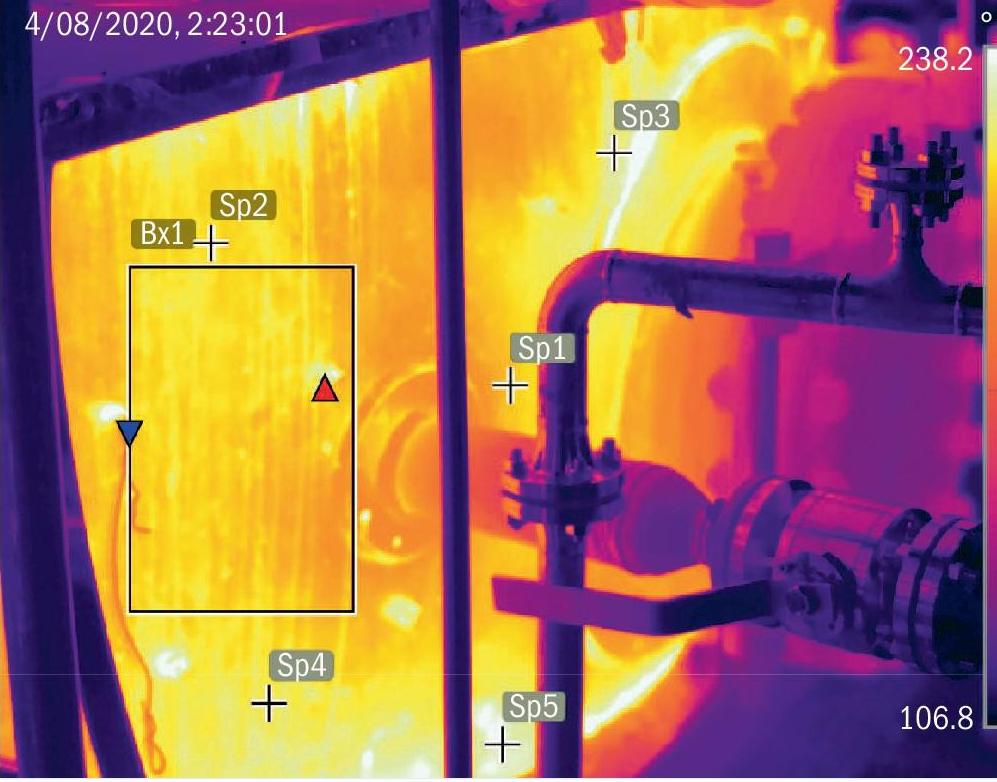
During the temperature ramp-up, external skin temperature measurement of the WHB rear channel was used (Fig. 8) to ensure that water was also completely removed from the castable refractory installed in the second reaction chamber.
As typically recommended for first start-ups, a stoichiometric run (i.e. fuel gas stoichiometric combustion with air and smothering steam) was also conducted at the end of the heating-up procedure in order to get the necessary experience and to consolidate air/fuel and steam/fuel ratios as well as the relevant control valves positions.
Acid gas cut-in
After unit heating-up was concluded, the acid gas cut-in procedure was started.
Once in stable conditions after cut-in, a portion of amine acid gas (AAG) was routed to the reaction furnace second zone as required to reach an operating temperature suitable for treating sour water stripper (SWS) gas.
Despite high acid gas bypass flow to the second zone of the reaction furnace (around 30%), the maximum temperature that could be achieved in the first zone of the reaction furnace was 1,190°C compared to a target temperature of 1,250°C.
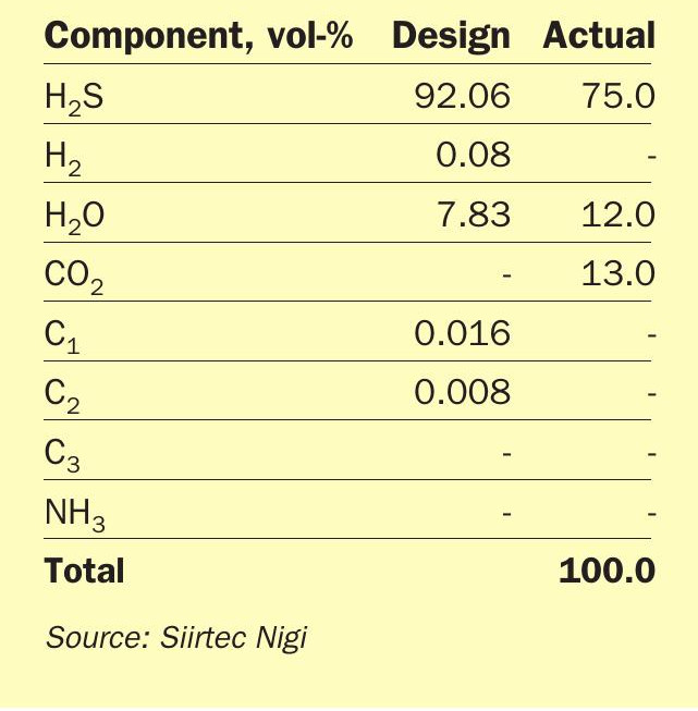
Ecopetrol’s team at the site confirmed that the AAG feed to the unit had a lower H2 S concentration than the one specified for the design. In fact, the AAG fed to SRU-IV was a blend of different acid gases from two amine regeneration units, one of them delivering a 91 vol-% H2 S rich acid gas and the second one only a 67 vol-% H2 S acid gas.
Actual estimated composition of AAG to the SRU-IV compared to the design figures is shown in Table 3.
The leaner gas composition had a greater amount of CO2 and H2 O, which resulted in a low reaction temperature. To compensate for this, besides adjusting the acid gas flow rate to the reaction furnace second zone, oxygen enrichment operation was also required.
Oxygen cut-in
In principle, oxygen cut-in is intended to be performed when the plant is operating with combustion air only, near to its maximum hydraulic limit and with a minimum oxygen flow rate in order to ensure a smooth transition.
Following Siirtec Nigi indications, oxygen cut-in was performed with a calculated initial overall enrichment level of about 33 vol-%.
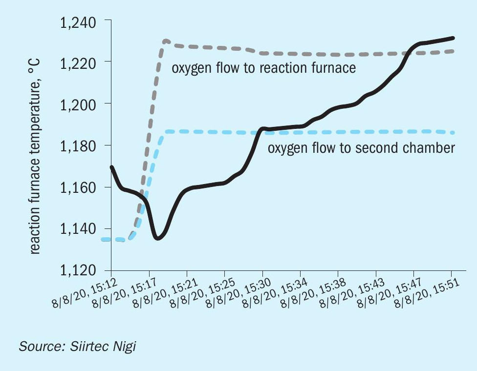
As expected, oxygen cut-in caused an increase in reaction furnace temperature to about 1,250°C in 30 minutes (see Fig. 9).
This modest temperature increase is consistent with SplitOxy scheme behaviour.
After cut-in, oxygen enrichment controller was finally adjusted to the nominal figure (36 vol-% overall oxygen enrichment). The unit was kept running in stable conditions; Siirtec Nigi remote support was concluded on August 11, 2020.
A new quest for higher flexibility
H2S-lean acid gases (like those used for the start-up of the SRU-IV in Barrancabermeja refinery) do not allow the proper temperature for ammonia destruction to be reached in the reaction furnace when treating sour water stripper gas with atmospheric combustion air only.
Operating a Claus unit with AAG and SWS gas under these conditions can be detrimental for downstream equipment since non-destroyed ammonia may form deposits of solid salts (ammonium sulphate, ammonium bisulphate, ammonium sulphide) at cold locations of the plant, such as condenser outlets.
In this regard, oxygen enrichment provides the benefit to increase reaction temperature by significantly reducing the amount of inert gas involved in the process.
In the SplitOxy scheme, overall oxygen enrichment and oxygen split ratio to second reaction chamber are carefully defined to enable the unit capacity increase while limiting the reaction furnace temperature at reasonable values.
Despite being designed with this target, the process still offers the flexibility to adjust the operating parameters when facing an unexpected reduction in H2 S content from acid gas feed.
To illustrate this, Fig. 10 shows the temperature trends in both the reaction furnace and second reaction chamber at different oxygen enrichment levels and split ratios.
At fixed oxygen split ratio to the second reaction chamber, the effect of the overall enrichment on the reaction furnace temperature in the SplitOxy scheme is generally negligible, whereas it has a tremendous impact on plant hydraulics.
On the other side, at fixed overall enrichment level there is a negligible effect on the plant performance (recovery and hydraulics) due to variations in oxygen split ratio, whereas it has a tremendous impact on the temperature envelope in the RF-WHB assembly.
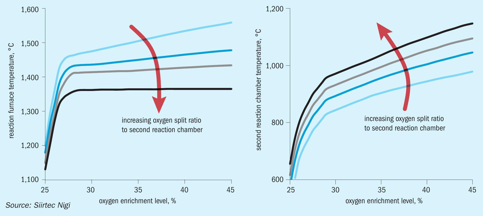
The lower the oxygen split to the second reaction chamber the higher the reaction furnace temperature. Also, the lower the oxygen split to the second chamber the higher is the effect of overall enrichment on the reaction furnace temperature, similar to the behaviour of a conventional oxygen enrichment burner.
The SplitOxy scheme still offers the flexibility to operate with reduced H2 S content, compared to design conditions, in the acid gas feeds by properly selecting a new oxygen split level to the second combustion chamber in order to enhance the effect of overall enrichment on the reaction furnace temperature.
Adjusted oxygen split levels must be thoroughly evaluated against oxygen system rangeability and the overall temperature/conversion envelope once the new composition is determined.
Summary
The SplitOxy novel dual combustion process scheme developed by Siirtec Nigi allows Claus plants to be designed for high-level enrichment without the risk of high temperature in the reaction furnace and has added operational advantages such as simple operating control, thanks to the embedded fixed oxygen split ratio.
The process can be applied in new units or as a retrofit to existing units.
When revamping an existing SRU with the target to increase the sulphur processing capacity, the economic advantages of the SplitOxy solution should be looked at in terms of number of items to be replaced and the relevant impact on layout.
Siirtec Nigi’s SplitOXY technology has also recently been supplied to another refinery in Italy, to improve operability and reliability of its original SRU without changing the unit sulphur capacity. It started up successfully in June 20201 .
Reference
LINDE / NESTE CORP.
Low level oxygen enrichment – field trial experiences and a new Claus unit application
Air has been used as the oxidant in Claus units since the 1930s, but today there is a clear trend to use at least moderate amounts of supplemental oxygen to enhance operational flexibility and plant reliability. Especially in refineries, applying low-level O2 enrichment (process air containing up to 28 vol-% oxygen) has gained considerable acceptance and importance.
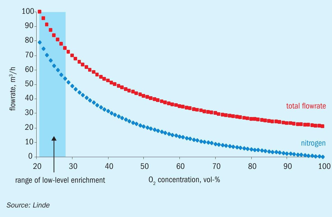
Low-level O2 enrichment is characterised by O2 injection into the Claus process air upstream of the Claus furnace, while at the same time reducing the flow of process air. As shown in Fig. 1, increasing the oxygen content in the process air while maintaining the original quantity of oxygen delivered, comes with ever more reduction of the nitrogen content. Respective curves show that this effect is most pronounced at low enrichment levels which e.g. explains that even low-level O2 enrichment typically allows for substantially enhanced feed throughput. Moreover, virtually all effects observed can be attributed to the reduced amount of inert gas being sent through the Claus unit, coming with increased reaction temperatures in the Claus furnace, higher residence time in the reaction stages, increased delta-T in the catalytic Claus reactors and less reheating effort (energy/ fuel saving) in general.
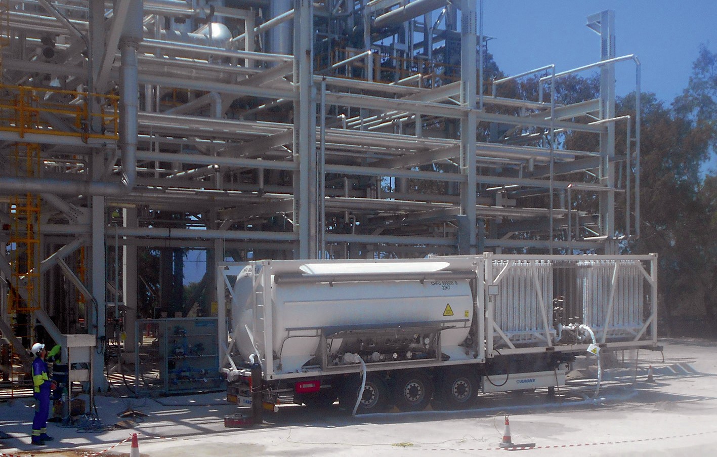
At present, probably up to 150 Claus units have implemented low-level O2 enrichment, an indication of the ease in which it can be physically implemented; i.e. in terms of hardware only the oxygen supply chain has to be realised (O2 source, control unit and injector). Implementation of the latter into the air pipe is the only point where the Claus installation must be modified. Low-level O2 enrichment is therefore not only a low investment solution for a revamp, it also lends itself to performing field trials in advance of an envisioned implementation; such trials can be easily carried out as all the equipment necessary can be rented from a gas company and then simply removed afterwards (a typical trial set-up is shown in Fig. 2).
Many operators have already opted for trials to compare the performance of actual routine operation (air-only) with O2 -enriched operation under different O2 -enrichment levels and load conditions; i.e. at the individual Claus unit revealing the effects and limitations of oxygen use. This is particularly useful e.g. for burner and waste heat boiler performance or ammonia (NH3 ) destruction efficiency, which are difficult to predict by simulation. Such trials provide reliable performance data for further planning of oxygen application. Over the last two decades, Linde has partnered with many refineries to carry out field trials, most of them in Europe.
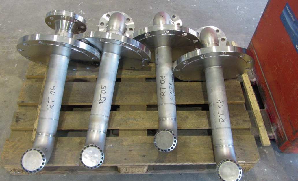
Linde also provided the preparation steps such as case analysis and tailor designed and built the respective O2 injectors (see Fig. 3), assuring fast and homogeneous gas mixing, which is of high importance.
Operating experience at Neste
One example in case showing many facets of low-level O2 enrichment application are the results of the long-standing cooperation between Linde and Neste, which operates two refineries in Finland – a smaller one at Naantali, organisationally attached to the major production complex near Helsinki at Porvoo (crude oil capacity: respectively 3 and 10.5 million t/a). At the latter refinery four Claus trains (4 x approx. 130 t/d) are operated and SWS-gas is added to the acid gas feed. Motivated by considerations about a future load increase and a temperature goal of minimum 1,250°C in the Claus furnace to be achieved by means other than co-firing, which had produced soot, Neste decided on a field trial at one of these Claus trains. In 2013 the trial run at design load and beyond was performed smoothly within one week and a consistent data set was produced allowing four different modes of low-level O2 enrichment operation to be compared with air-only operation, the latter with and without co-firing of fuel. The trials showed that at the maximum low-level O2 enrichment level of 28 vol-%, the feed throughput can be increased by approximately 30%, an improvement which is not unexpected when compared to results from other refineries. The trial showed that the application of co-firing in air-only mode at reasonably high plant load (near to design) is clearly inferior to low-level O2 enrichment application in many aspects. With co-firing, appreciably higher process gas volumes are generated according to the stoichiometry of fuel combustion by air, thus reducing the plant capacity. At comparable Claus furnace temperatures and at a moderate O2 enrichment level of 24 vol-%, the residual NH3 content was found to be about 60% less than when applying co-firing in air-only operation. In addition, due to fuel savings at different consumers all the way down from the Claus furnace to the incinerator, low-level O2 enrichment also turned out to be the most favourable option as regards the economics. Accordingly, immediately after these trials Neste decided to implement low-level O2 enrichment at all four Claus units. Operation with oxygen started up in 2016 and has been in permanent use ever since, i.e. also when no additional acid feed has to be processed. The new operating strategy was well received by the operators in the control room who experienced smoother plant operability with low-level O2 enrichment, a general trend observed at other refineries as well.
Oxygen enrichment plus co-firing at very low load
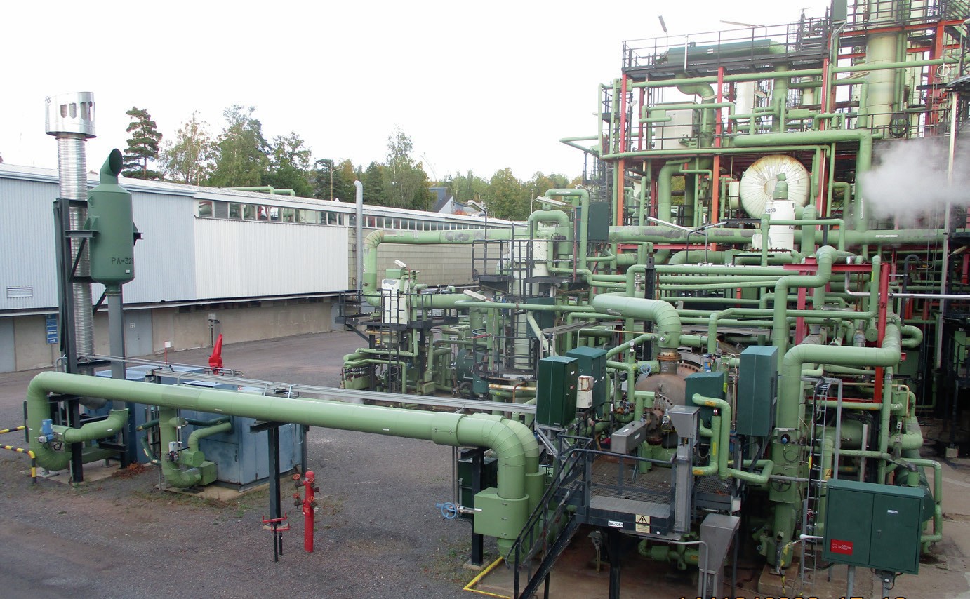
Compared to Porvoo, at Naantali refinery the Claus situation and history of oxygen application has been very different. Here, only one Claus unit is operated (Fig. 4), also equipped with EuroClaus like the Claus units in Porvoo, but less than half their size. Back in 2006 Neste was expecting additional Claus feed in the near future and implemented low-level O2 enrichment using oxygen supply, control and injection hardware provided by Linde. However, the feed load increase never materialised, and the plant was typically operated in air-only mode at around half of its design capacity, including SWS gas processing. In 2011, the Naantali refinery invited Linde to perform NH3 sampling and measurements in air-only mode compared to different low-level O2 enrichment levels. As expected, the results showed that with increasing low-level O2 enrichment level and correspondingly rising temperature, as well as prolonged residence time in the Claus furnace, the efficiency of NH3 destruction can be enhanced significantly1,2 . This came as no surprise as all previous NH3 measurements at other sites had shown the same trend.
At Naantali, the residual NH3 found in the process gas at constant feed load conditions was as follows: 330 ppmv (air-only) vs 105 ppmv (25% O2 enrichment) vs 75 ppmv (26.5% O2 enrichment). Soon after seeing the results of the NH3 measurements, Naantali started to apply low-level O2 enrichment on a permanent basis with the main goal of achieving a Claus furnace temperature of minimum 1,300°C to minimise NH3 -related issues2 . However, in 2017 the thermo-catalytic cracker was decommissioned, thus reducing the acid gas baseload for the refinery and since then on recurring occasions the Claus feed load has dropped considerably and low-level O2 enrichment was stopped as it was approaching its limitation under pronounced turn-down conditions; i.e. when the Claus furnace temperature is comparably low as “fuel” (H2 S) input is decreased at constant heat loss. Here gas velocities of Claus feed and combustion air are already low and O2 enrichment would aggravate this situation by even further decreasing process air flow; this in turn would move the hot flame ever nearer to the burner tip, thereby jeopardising material integrity. Mainly due to this reason and until only recently, application of O2 enrichment was generally not recommended for low-load operation and operators apply other means for temperature increase, in particular co-firing of hydrocarbons. Even though this measure comes with appreciable disadvantages such as increased risk of soot generation, it is frequently applied in turn-down situations, i.e. can be viewed as ‘state-of-the-art’.
In the Porvoo field trials, the combination of co-firing and low-level O2 enrichment was inferior to low-level O2 enrichment only application – but this was at high load conditions. So, faced with the recurring low-load situations at Naantali where soot had already been found in the Claus unit after co-firing of refinery gas, Neste’s engineers decided to review this approach again; they investigated whether, if using a comparably moderate fuel amount together with oxygen, promising high furnace temperature (still aiming for 1,300°C) at reduced risk of soot generation, it would be feasible to keep the original overdesigned Claus burner (design: 2,800 kg/h acid feed).
Supported by Linde, the licensor Comprimo and the burner supplier Duiker they found a solution which included downsizing some of the equipment, e.g. flow valves for air and oxygen supply. Naantali refinery started to apply the combined fuel/oxygen concept in 2018 in pronounced low-load situations which sometimes go down as low as 430 kg/h acid feed, i.e. to a turndown rate of 15%2 .
At Naantali, O2 enrichment in refining was established as a vital part of a new concept for mastering low-load operation; i.e. O2 use at Claus units further broadened its versatility, meeting operational challenges ranging from extended feed load all the way down to low load situations.
At present Neste applies low-level O2 enrichment at all Claus units of both refinery sites on a permanent basis, thereby confirming the observation by Brimstone (2019) that “Improved reliability has emerged as the number one goal for most sulphur and amine plant operators”.
References
BLASCH PRECISION CERAMICS
Optimised VectorWall™ geometries for higher front zone Claus reaction furnace temperatures
The reaction furnace (RF) is the most important equipment component in the sulphur recovery unit (SRU) since it is where about two thirds of the feed hydrogen sulphide is converted to elemental sulphur. The RF also plays a critical role in the processing of hydrocarbons, ammonia and BTEX (benzene, toluene, ethylbenzene and xylene) that often constitute a portion of the feed and if not adequately destroyed can have a serious deleterious impact downstream in the SRU. Overall, achieving these goals requires the careful calibration of the time, temperature and turbulence (the 3Ts of combustion) in the RF.
The residence time which is set by the RF volume and total flow rate (process feeds, combustion air/oxygen and possibly fuel gas) must be adequate for the myriad reaction mechanisms to reach completion or equilibrium as the case may be. Good mixing (turbulence) along the entire length of the RF is required to make sure that the reactants “see” each other and there is no stratification of the feed or combustion air such that conversion of the H2 S to sulphur or contaminant destruction is compromised. This is particularly important in front/side split operations where some of the amine acid gas (AAG) bypasses the burner and is fed downstream in the RF to achieve higher temperatures in the front zone of the RF. Finally, temperature plays an absolutely critical role in the RF, especially in achieving the desired temperature for BTEX and ammonia destruction which require temperatures of 1,050 and 1,300°C respectively. Achieving these temperatures is predominantly set by the strength of the AAG feed but can also be impacted to some degree by burner design and the aforementioned front/side split operation.
Reaction furnace internals such as checkerwalls and choke rings are commonly used in a RF to improve mixing, increase the temperature in the front zone and protect the waste heat boiler tubesheet to varying degrees. An enhancement to these structures that is much more structurally robust and provides additional benefits including better mixing and higher residence times and front zone temperatures is the Blasch VectorWall™ (Fig. 1). These have been demonstrated to provide higher capacities, better flame stability, better contaminant destruction and much longer run lengths compared to conventional systems (Sulphur, March-April 2018). In the context of the 3Ts of combustion, this section focuses on temperature and the various methods used to influence this extremely critical parameter in the reaction furnace and the complementary role of the VectorWall.
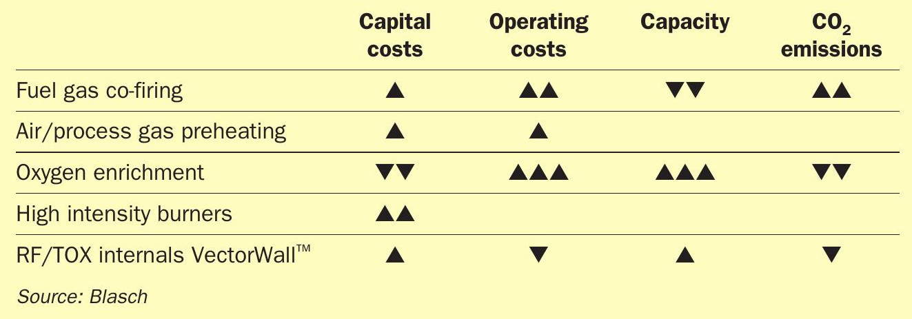
Lean acid gas feeds offer a significant challenge in achieving stable combustion and contaminant destruction in the RF. Fuel gas co-firing, combustion air/process gas preheating, oxygen enrichment and high intensity burners are used singly or in combination to achieve the desired RF temperature. Table 1 depicts the qualitative impact of these schemes in terms of the capital and operating costs related to their implementation and their impact on SRU capacity and carbon dioxide emissions. The exact impact is unique to each SRU and dependent on the specific feed compositions, flow configuration and burner and RF internals.
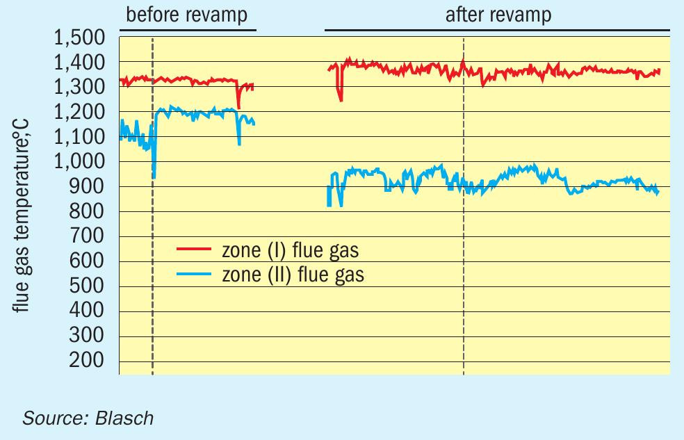
The Blasch VectorWall has been shown to increase the front zone RF temperature as seen in Fig. 2, which compares the temperature before and after a VectorWall revamp of an SRU at a refinery in Asia. It can be seen that the Zone 1 temperature increased by about 75-100°C after the revamp. This was key to solving the problem of ammonia destruction and the deposit of ammonium salts downstream that were plaguing the refinery prior to the revamp. Blasch has since focused on how the geometry of the VectorWall tiles can be optimised to further enhance temperature increases in the RF front zone while also minimising the pressure drop across the wall. For example, the geometry can be designed to provide full shielding of the flame, further minimising radiation heat loss from the front zone and hence enhancing front zone temperatures.
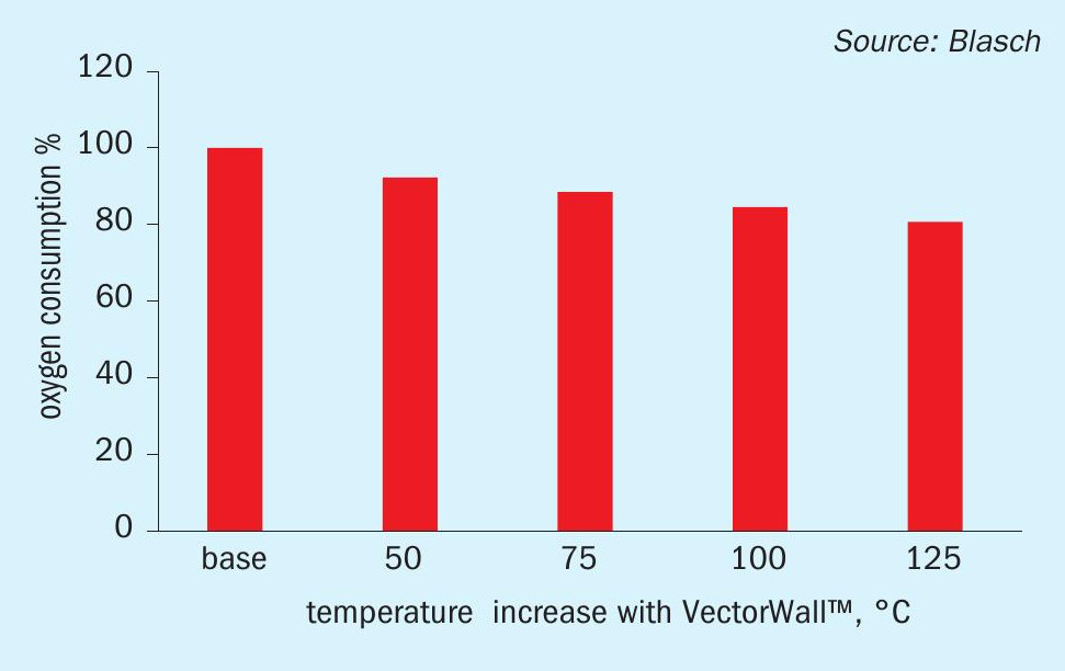
The main driver for oxygen enrichment of SRUs since the inception of this technology in the mid-1980s has been achieving capacity increase in the sulphur complex without having to build costly new SRUs. Technologies exist for oxygen concentrations ranging from mid 20% to 100%, at which level the capacity of an SRU can be more than doubled. An especially important benefit of oxygen enrichment is that it also significantly increases the RF temperature thus providing much better ammonia/BTEX destruction while also reducing or eliminating the need for front-side split operation and air/feed preheating. By increasing front zone RF temperature as illustrated, the Blasch VectorWall also provides the same temperature enhancement benefits and thus can be used synergistically to optimise oxygen-based operation. Fig. 3 illustrates how a potential 8 to 20% reduction in oxygen consumption can be realised from the revamp of an O2 -based SRU with a VectorWall. This offers significant operational savings while also providing the additional intrinsic benefits such as better downstream mixing, beyond that achievable by a burner, and superior residence times for more reliable operation.
Another scenario of interest in the context of RF temperature is the ability to cut fuel gas co-firing rates with a Vector-Wall revamp and still achieve the same desired temperatures. Very importantly, this also helps provide a significant capacity increase since each mole of reduced fuel gas firing results in a reduction of 11 moles of flue gas through the process. For a 500 t/d SRU, a front zone temperature increase of 100°C and fuel value of $3/million Btu, energy savings of over $250,000 per year are realised.
RAMESHNI & ASSOCIATES TECHNOLOGY & ENGINEERING
Recovering H2 S and CO2 from waste streams
Some refinery residuals, gases, or materials that until recently would have typically been disposed of as waste materials or waste streams are now required to be recovered in the form of useful products to support new environmental regulations.
Recently, Rameshni & Associates Technology & Engineering (RATE) has been working on a project to control SO2 and CO2 emissions in Europe. The technologies used in this project are unique, and use proprietary designs patented by RATE.
Recovered H2 S is converted to sulphur in a sulphur recovery unit using oxygen enrichment technology. The recovered CO2 is compressed and sent to the RATE proprietary CO2 liquefaction unit for further purification before being reinjected or used in other applications such as a transport medium for conveying solid waste, a pressure medium for the lock hopper system, seal gas for screw feeders or for stripping gas as used in this project.
This project faced many challenges regarding the design of the sulphur recovery unit and the acid gas removal section due to the different feed compositions and impurities to these units.
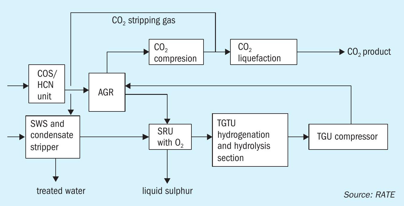
Waste management plants require a quench system, COS/HCN hydrolysis, waste water treatment, AGRU, SWS, SRU, and CO2 removal.
The flow diagram in Fig. 1 represents the configuration of the project for major units.
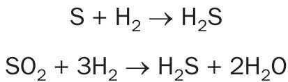
In the COS/HCN hydrolysis section, COS and HCN will be catalytically converted into H2 S, CO2 and NH2 according to the following hydrolysis reactions:
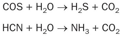
In the CO shift reactor, CO is converted to H2 according to the water gas reaction:

The gas stream from the hydrolysis section flows to the acid gas removal (AGR) unit where a physical solvent like Selexol or similar is used. In the AGR unit, the treated gas containing high CO2 is sent to the CO2 liquefaction unit to purify the CO2 product further. The acid gas stream from the AGRU is sent to the sulphur recovery unit.
A slip stream of CO2 is used as the stripping gas for the process condensate stripper to strip the H2 S. This scheme is also a proprietary design and unique for this application.
The SWS and condensate stripper comprises two separate stripper columns: the process condensate stripper and the NH3 stripper.
The first treatment step is the removal of sour gases and volatile components in the process condensate stripper. The liquid phase of the process condensate flash drum is preheated and fed to the stripper column in between the upper and middle packing. The process condensate stripper column consists of two sections. In the upper section, CO2 stripping gas is utilised to remove H2 S and to minimise the stripping of NH3 . In the lower section, volatile components and CO2 are removed by means of uprising steam. Any dissolved carbonates are thermally decomposed. The stripped water is routed to the NH3 stripper where NH3 is removed and mixed with H2 S from the other stripper before being routed to the sulphur recovery unit.
As already mentioned, the design includes COS/HCN hydrolysis however, there is still some HCN and COS than is not fully hydrolysed flows to the AGRU unit and eventually reaches the sulphur recovery unit. HCN can be washed as well as combusted in the reaction furnace and an additional feature is provided in the TGTU unit to hydrolyse all the remaining of COS.
There are a number of units in this plant, including the sulphur recovery unit, which require oxygen enrichment. In gas plants and refineries, oxygen enrichment technologies are used to expand the sulphur recovery capacity or to reduce the number of trains in gas plants. Oxygen enrichment raises the flame temperature by eliminating the diluent effect of nitrogen in air. An economical source of oxygen is the key in this case.
However, in waste recovery or waste management plants the sulphur recovery units are designed to boost the temperature to destroy the impurities entering the SRU. Therefore, even with 100% oxygen enrichment, neither staged combustion nor recycling are required to maintain the temperature of the refractory, single combustion is adequate.
Carbonyl sulphide (COS) requires hydrolysis to convert it to hydrogen sulphide to improve emissions and overall sulphur recovery. Traditionally, if titanium dioxide-based catalyst is used in the first Claus reactor, about 98% of the COS will be hydrolysed, the remainder being hydrolysed in the tail gas hydrogenation reactor. But sometimes, owing to different feed compositions from the upstream units, it may be required to have a separate COS hydrolysis reactor. In summary, the following units were considered for this project.
- The acid gas removal scheme used Selexol physical solvent or similar.
- The SWS and condensate stripper is a unique design where CO2 is used as the stripping gas.
- The design of the sulphur recovery unit is based on 100% oxygen enrichment and single combustion.
- The tail gas unit contains an additional reactor for COS hydrolysis and to process one of the feed streams directly to maintain a high temperature in the SRU.
- The tail gas unit is designed to recycle the quench overhead to the acid gas removal unit, whereby the tail gas amine portion is eliminated and zero sulphur emission is achieved.
Detailed description
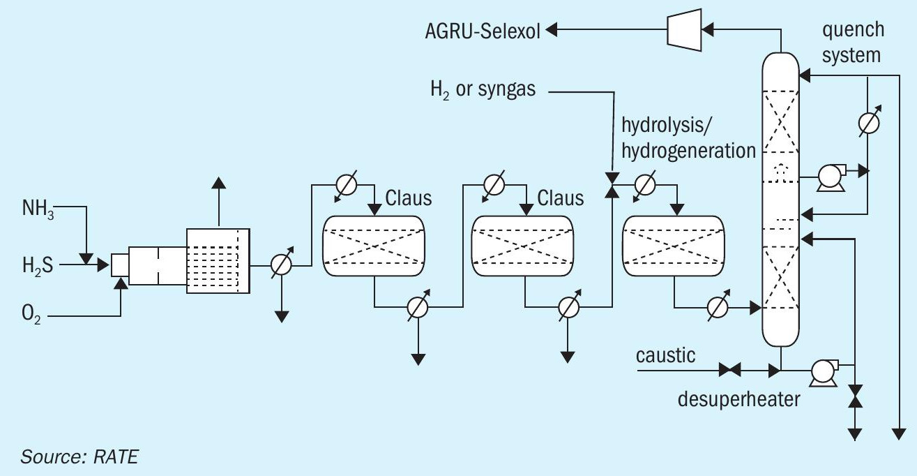
The block diagram in Fig. 2 represents the sulphur recovery with 100% oxygen enrichment plus the hydrogenation reactor, hydrolysis reactor and the quench system. The tail gas treating unit does not need an amine section, instead the quench overhead is recycled back to the AGRU unit through a compressor where H2 S and CO2 are separated and as a result there is no SO2 emission from the SRU/TGU.
If not properly destroyed, hydrocarbons in the acid gas feed often cause carbon laydown on the catalyst and the generation of undesired high concentrations of COS and CS2 . In addition, ammonia in the acid gas feed often causes deposition of complex ammonia/sulphur salts in cooler parts of the plant. These undesired phenomena can cause unscheduled plant shutdowns, reduce sulphur recovery and shorten catalyst life. Oxygen enrichment raises the reaction furnace temperature which ensures complete destruction of heavy hydrocarbons and ammonia, reduces the formation of COS and CS2 , and shortens the gas residence time required to destruct contaminants.
In case of lean acid gas feed contaminated with high levels of heavy hydrocarbons, Oxygen enrichment offers an inexpensive and simple solution to circumvent this otherwise unsolvable problem that requires costly processing technology.
The oxygen burner has proved to be very effective in destroying ammonia and hydrocarbons in Claus plants. Outside of its application in Claus plants, oxy-fuel burners are widely used in the metals and minerals and in the chemical and refining industries to burn a wide range of fuels, including gases, liquids, and pulverised solids. One of their most attractive features is their ability to burn heavy residual hydrocarbons cleanly.
Two major effects in using oxygen or oxygen-enriched air in place of air for combustion are higher temperatures and higher flame speeds. The degree of change depends on the degree of oxygen enrichment, but in the case of pure oxygen, temperatures may increase by 1,050°C and flame velocities by ten times in round numbers. The combination of these two effects is to produce a hotter, shorter, more intense flame much better suited to the rapid destruction of combustible materials.
The destruction of individual feed components in a Claus unit cannot be considered in isolation, since there is considerable molecular interaction. Both hydrogen sulphide and ammonia dissociate quite readily and the higher the temperature, the higher the level of dissociation. The result is that when oxygen is used, the hydrogen level in the reaction furnace increases greatly compared to that achieved in air-based systems. Most of this hydrogen will subsequently recombine with sulphur in the waste heat boiler (WHB), including hydrogen produced from ammonia dissociation. The ammonia must effectively be burned, even if the mechanism of destruction is initially dissociation, in order to preserve the Claus Stoichiometry downstream of the WHB.
It can be speculated that the hydrogen remaining in the gas after the WHB will be higher if the level in the reaction furnace before the boiler is higher. This must be true if the quench rate in the boiler remains constant. The effect may be small however, and in the case of up rating with oxygen, where the WHB sees a higher load, a fall in quench rate may reduce it still further.
The AGRU is designed to separate the H2 S, which is sent to the sulphur recovery unit to produce sulphur as the product. The CO2 is also separated and compressed to be used as the product. The SWS and the condensate tower also remove H2 S and ammonia and send them to the sulphur recovery unit.
The sulphur recovery unit receives two acid gas streams containing HvS and NH3 . As we know, the ammonia can be destructed in the thermal section, but unfortunately the H2 S entering the SRU is very lean and cannot establish an adequate combustion temperature of at least 1,050°C to achieve the successful burning of ammonia with air-only operation. This project is therefore designed with 100% oxygen enrichment in single combustion. Also on account of the lean acid gases, even with Ti catalyst in the SRU converters, the significant COS and CS2 produced in the reaction furnace would not be fully converted to H2 S in addition to the feed compositions contained COS.
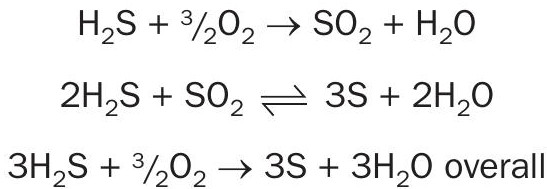
Ammonia, which can form undesirable sulphur compounds, must also be destroyed in the combustion process:
The sulphur recovery unit is designed with a thermal section featured 100% oxygen enrichment and two catalytic reactors.
The tail gas stream from the last condenser flows to the hydrogenation reactor in the tail gas treating unit containing low temperature CoMo catalyst and using indirect steam reheaters.
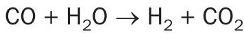
H2 and CO present in the tail gas from the Claus units reacts with the sulphur vapour and SO2 in the tail gas over a catalyst bed to form H2S. The hydrogenation catalyst also promotes the hydrolysis, i.e. reaction with water, of COS and CS2 to form H2S. Hydrogenation and hydrolysis reactions for the four primary sulphur constituents are as follows:
Hydrogenation reactions
Hydrolysis reactions
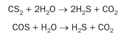
CO does not react directly, but is converted to H2 over the catalyst by the water shift reaction:
These reactions are exothermic.
The outlet of the hydrogenation reactor cools off and then flow to the proprietary design hydrolysis reactor. The outlet of this reactor flows to the quench system.
Tail gas is desuperheated in a bed of grid-type packing in the lower section of the column by a circulating water stream pumped by the desuperheater circulating pump. This water is maintained alkaline to protect against any SO2 breakthrough from the hydrogenation reactor. The desuperheater section is initially filled with a 10-wt% caustic (NaOH) solution. This solution quickly reacts with the CO2 in the tail gas to form a sodium carbonate/bicarbonate (Na2 CO3 /NaHCO3 ) buffer solution.
Any SO2 that breaks through from the hydrogenation reactor will react with the solution to form sodium sulphite/bisulphite (Na2 SO3 /NaHSO3 ). Periodically, as the carbonate/bicarbonate is depleted, a portion of the solution is drained to the spent caustic system and replaced by fresh caustic solution. The spent caustic is cooled in the spent caustic cooler and then sent off-plot for disposal.
The gases exiting the quench column are normally routed to the Selexol unit through a compressor.
Back-up incineration is also provided for abnormal conditions where the quench overhead flows to the incinerator instead of recycling back to the AGRU.
Carbon capture usage and storage (CCUS) is not only an important to mitigate industrial CO2 emissions and reduce environmental footprint, it also enables valuable and cleaner burning gas previously used for EOR, for power generation desalination and industrial usage.
Many oil companies recognise CCUS technologies in tandem to tie in with gas conditioning within an overall circular carbon economy policy taking advantage of the technologies to reduce, recycle, reuse and remove CO2 , as well as employing artificial intelligence and big data, to reduce emissions by monitoring energy consumption and optimising operations.
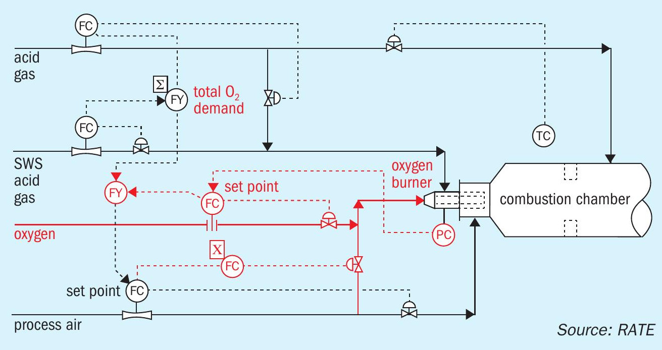
The sulphur recovery design using high purity oxygen enrichment has exclusive criteria and safety considerations. One of the most important features is to design the control system and the burner management system to establish a safe environment for the operation team at the facility. The diagram in Fig. 3 represents the control system and the burner management system where oxygen enrichment has been added to the design of the sulphur recovery unit.
Safety concerns around SRU oxygen enrichment are two-fold:
- the introduction of oxygen to a new plant area;
- changes in design and equipment from a conventional air-based SRU.
The following safety features should be incorporated into the DCS and burner management systems.
- Oxygen and natural gas should be interlocked so that they are not introduced to the burner at the same time.
- The oxygen line should be equipped with automated double isolation safety blocks and bleed to a safe location (similar to natural gas).
- Suitable material should be selected for the oxygen line, valve and any other instrumentation.
- A proper shutdown system should be provided to prevent equipment damage during oxygen enrichment operation at high temperatures.
There is no doubt that the presence of oxygen requires operators to exercise additional safety precautions; but operators and designers are gaining more experience and higher comfort level in handling oxygen in hydrocarbon rich areas. The necessary materials, safeguards and operating procedures for handling oxygen are well defined and understood. Furthermore, the oxygen distribution system should be designed with minimum inventory near combustibles.
Fig. 4 shows the process flow diagram for the thermal section using 100% oxygen enrichment. The catalytic section is not shown because it is the same as air operation scheme.
The advantages of using oxygen enrichment are to establish stable combustion temperature where NH3 can be fully destructed in the reaction furnace burner among other impurities that enter the sulphur recovery unit. Oxygen enrichment will reduce the size of the equipment, resulting in lower capital costs and also improves the sulphur recovery efficiency. The advantages for the tail gas unit when using oxygen enrichment in the SRU is that the equipment for tail gas treating will also be smaller, resulting in lower capital cost and again better performance. Oxygen enrichment reduces the plot area required for SRU capacity expansion and for operating facilities limited by plot space, oxygen enrichment may be the only viable option.
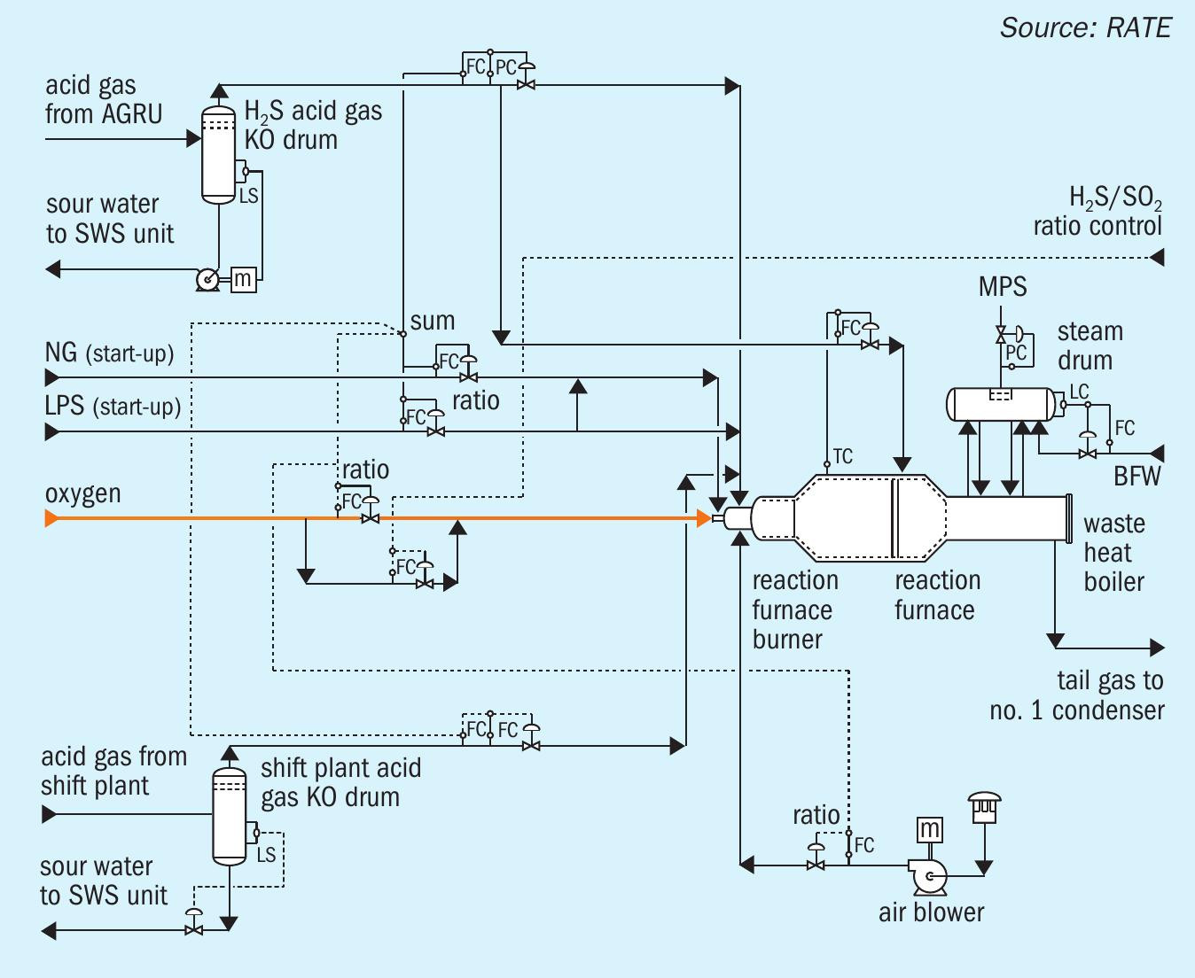
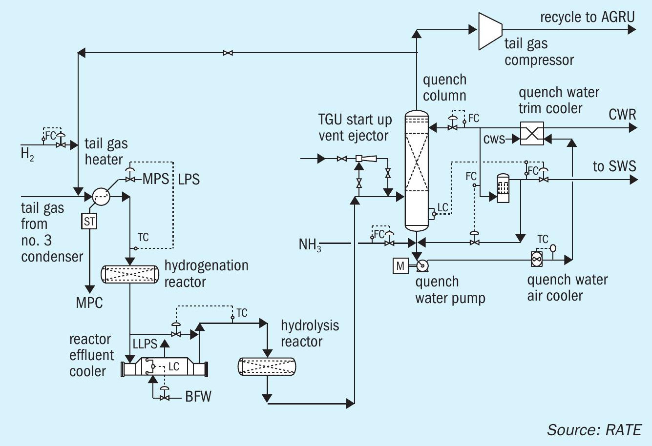
Fig. 5 shows the tail gas treating unit with hydrogenation and hydrolysis reactor and the quench system.
FLUOR ENERGY & CHEMICALS
Fluor’s Oxygen Enhanced Claus Carbon Dioxide Recovery Process (OEC2 RP)
Weather change occurs in many places around the world causing icebergs to melt quicker; sea level to rise, unusual high daily temperatures, heavy rainstorms and tornados. These all occur partly due to the increasing presence of carbon dioxide (CO2 ). Unfortunately, a high percentage of the CO2 emitted to the atmosphere is related to emissions from oil and gas, chemical and power industries.
To mitigate these undesired weather changes, CO2 emissions need to be reduced from these industries. During the last couple of decades, much research effort has been focussed on recovering CO2 from emission streams such as acid gases from amine absorber overhead effluents and tail gas effluents from Claus tail gas treating unit amine absorber overheads. However, it is known to the industry that recovering CO2 is a very energy intensive exercise. Due to the acidic nature of this gas stream, expensive materials have to be used to mitigate corrosion issues on equipment. Thus rendering all processing plant utilising CO2 Recovery technologies with high capex and opex requirements.
Fluor’s patent-pending Oxygen Enhanced Claus Carbon Dioxide Recovery Process – OEC2 RP was invented to provide a stateof-the-art cost effective method to recover CO2 from gas effluent of the Claus tail gas treating unit amine absorber overhead.
This carbon dioxide recovery technology is designed specifically for recovering CO2 from the SRU/TGTU facility of gas plants, although it is applicable for any SRU/TGTU facilities. Gas feeds to Claus sulphur recovery units typically contain a very high percentage of CO2 in gas plants, thus rendering recovery from the Claus tail gases more economical and worthwhile.
This technology works well with oxygen enrichment technology in SRU/TGTUs and offers opportunities around a SRU/TGTU revamp to improve the profitability of a facility while meeting environmental objectives. The flexibility of these technologies provides substantial economic and process advantages for a wide range of applications over competing solutions.
Fluor’s patented COPE® oxygen enrichment Claus TEchnology can provide an economical solution for the expansion of existing facilities and a more cost effective solution for new facilities, while providing significant process benefits. COPE I® and COPE II® oxygen enrichment Claus technology have low life cycle costs (low capex and opex) and have been implemented in over 80 sulphur recovery facilities worldwide from small scale to world scale plants.
Oxygen enrichment Claus operation
Why consider implementation of oxygen enrichment technology into the Claus operation for existing SRU/TGTUs? Oxygen enriched Claus operation offers the following benefits to enhance the current SRU/TGTU operation in terms of operation flexibility and reliability:
- enhances the Claus reaction furnace (RF) operating temperature;
- potentially mitigates requirements of fuel gas co-firing in attaining sufficient temperature for achieving complete BTEX and ammonia destruction;
- the enhanced RF operating temperature facilitates dissociation of H2 O molecules to form H2 , which in turn facilitate the hydrogenation reactions in the TGTU hydrogenation reactor with much more excess H2 compared to Claus air operation. This benefit is especially welcome for gas plant operation as usually a gas plant facility does not have another source of H2 which might be needed for the hydrogenation reactor operation during unexpected mal-operation of upstream processing units;
- requires minimum modifications of existing equipment especially for gas plant SRU/TGTUs;
- reduces overall volumetric gas flow through the entire SRU/TGTU facility, thus enhances acid gas processing capacity;
- reduces pressure drop across the entire SRU/TGTU facility, thus might mitigate the need of higher amine acid gas battery limits inlet pressure to the SRU facility;
- enhances Claus sulphur recovery efficiency;
- minimises equipment size of new SRU/ TGTUs, thus reduces capex and opex of new SRU/TGTUs;
- reduces Plot Sizes of new SRU/TGTUs. Oxygen enrichment technology is especially beneficial to gas plant SRUs because amine acid gas feed to the existing SRUs is lean in H2 S and usually contains some amounts of BTEX, which usually requires higher temperature, say >1,100°C for complete destruction. By eliminating the potential requirement of fuel gas co-firing, potential carbon deposition in the first catalyst bed due to cracking of fuel gas will be mitigated. This technology also reduces volumetric gas flow rate due to the absence of nitrogen in the pure oxygen thus helps any pressure drop issues across the plant and provides increased acid gas processing capacity.
Table 1 provides comparisons between air Claus operation and various levels of oxygen-enriched air Claus operation.
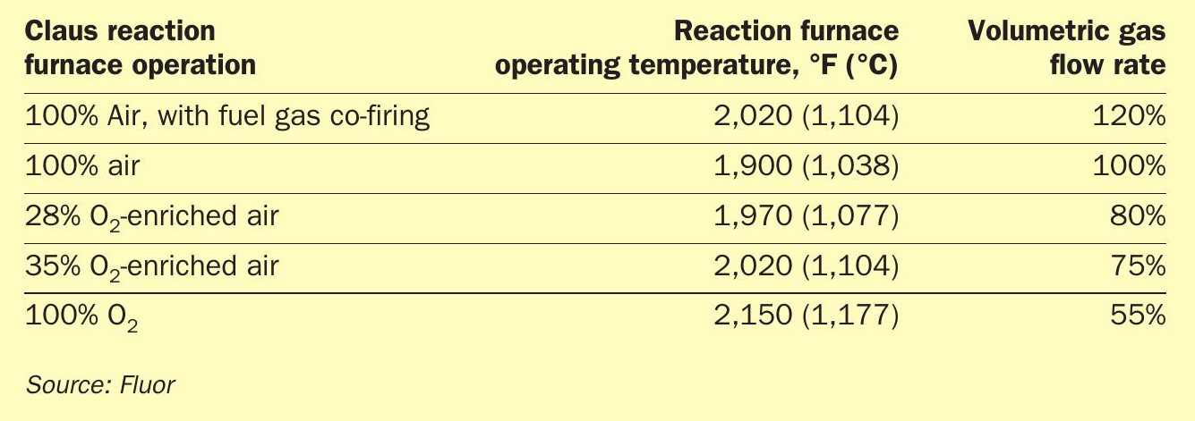
As indicated in Table 1, for the SRUs in this gas plant study, even operating with 35% O2 -enriched air, the RF temperature is still only 2,020°F (1,104°C), but the volumetric gas flow is reduced by 25%. The oxygen burner may be the only equipment item that needs to be replaced when implementing this technology. While operating with 100% O2 , the RF temperature is only about 2,150°F (1,177°C). The required equipment modification is most likely just the RF oxygen burner and possibly the first sulphur condenser. However, the volumetric gas flow rate is reduced by more than 45% providing lots of spare or additional acid gas processing capacity.
Oxygen Enhanced Claus Carbon Dioxide Recovery Process (OEC2 RP)
While implementing 100% O2 for the Claus operation, not only is the Claus tail gas flow rate to the TGTU greatly reduced, there will also be no or only a very minute amount of N2 present. As a consequence, the main components in the feed gas to the TGTU amine absorber will be H2 , H2 S, H2 O and CO2 . Highly selective amine such as formulated MDEA could be used to remove the H2 S component to less than 10 ppmv in the amine absorber overhead effluent prior to being vented to the atmosphere via a thermal oxidation/stack.
In addition, sterically hindered amines such as ExxonMobil’s Flexsorb™ SE and SE Plus and BASF/ExxonMobil’s OASE® Sulfexx™ have the capability to slip over 95% CO2 , yielding an amine absorber overhead effluent gas containing less than 10 ppmv of residual H2 S but over 95% of all the CO2 in the absorber feed gas.
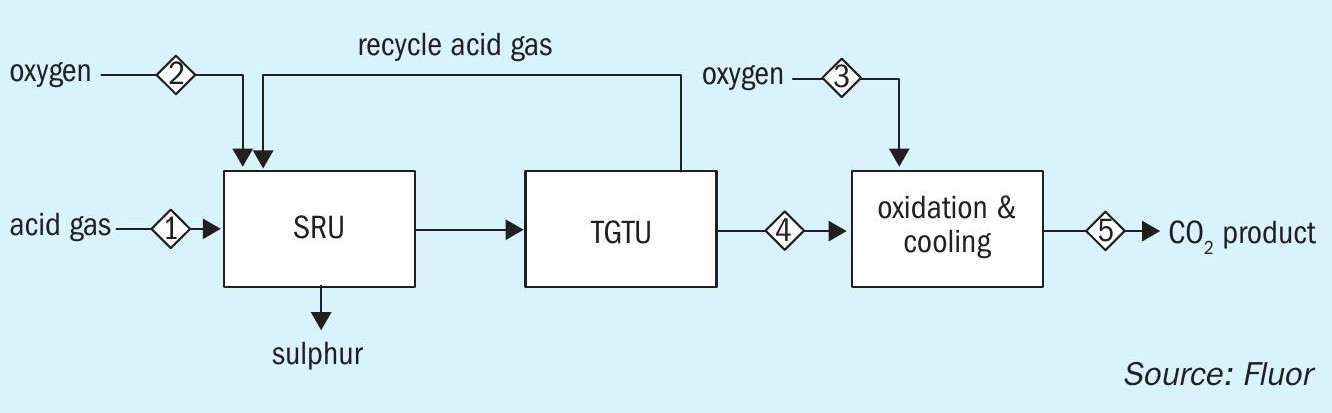
One of the process configurations of Fluor’s Oxygen Enhanced Claus Carbon Dioxide Recovery Process involves the conversion of hydrogen to water via oxidation and quenching/cooling of the hot gas stream. For a 100% oxygen enriched SRU/TGTU, the product from the OEC2 RP is a very pure carbon dioxide stream capable of being used for EOR after compression and dehydration. The purity of the CO2 stream is determined primarily by the purity of the oxygen used for oxygen enrichment. For instance, if a 99.5% oxygen stream with 0.5% nitrogen is used, the CO2 stream from the OEC2 RP will be >98% CO2 on a dry basis. Fig. 1 is a simplified block flow diagram showing the how OEC2 RP is integrated into a sulphur recovery facility.
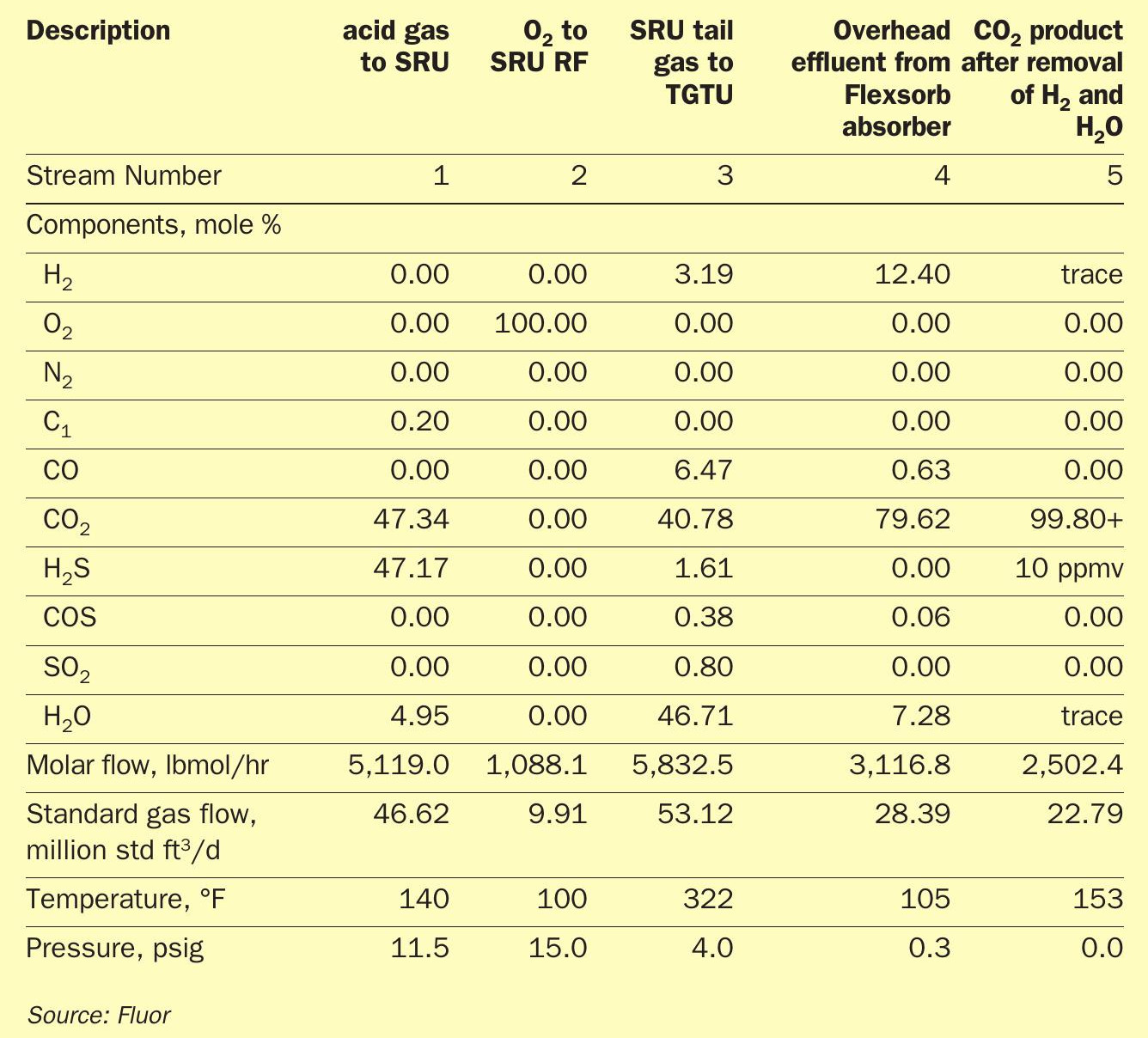
Table 2 shows the product streams of a SRU/TGTU operating with 100% O2 from a case study for one of Fluor’s clients. The absorber overhead effluent will mainly contain about 80% CO2 , 13% H2 , and 7% H2O. Followed by proven processing steps of removing the H2 and H2 O components, the product CO2 will have a purity of over 99+%. The H2 component could be recovered as a product stream via known processes such as membrane separation, PSA or a cryogenic system depending on the end users of the CO2 and H2 .
The key benefits of OEC2 RP are much lower capex and opex relative to conventional investment and energy intensive CO2 recovery processes. Due to its simplicity OEC2 RP also has a small footprint which is a significant advantage in space constrained facilities.
References