Sulphur 425 Jul-Aug 2026
Overcoming the complexities of liquid sulphur pipeline transport


SULPHUR HANDLING

Overcoming the complexities of liquid sulphur pipeline transport

Akanksha Pandey, Vaneet Garg, and Debopam Chaudhuri from Fluor discuss the unique challenges associated with transporting liquid sulphur through pipelines and present key design considerations and operational strategies that enable safe, continuous and reliable long-distance operation.

Elemental sulphur is an inherent by-product of modern refining processes, generated during hydro-desulphurisation and subsequently recovered in sulphur recovery units (SRUs) using modified Claus and tail gas treatment technologies. The recovered sulphur is typically handled in molten form at temperatures between 130°C and 150°C, safely above its melting point of approximately 119°C.

While molten sulphur storage is suitable for short-term buffering, bulk transportation is generally carried out in solid form due to its operational simplicity and reduced thermal risk. However, in many refinery configurations, sulphur solidification and handling facilities are located significant distances from the liquid sulphur storage tanks, often extending over several kilometres. In such cases, maintaining sulphur in a fully molten state throughout the transfer pipeline becomes a critical design and operational requirement.

Long-distance liquid sulphur transport presents multiple engineering challenges. These include maintaining uniform temperature profiles to prevent cold spots and solidification, avoiding excessive heating that may promote sulphur polymerisation or material degradation, and accommodating thermal expansion across extended pipeline lengths. Additional complexities arise from heat loss to the environment, fluctuating operating conditions, and stagnant zones that can accelerate cooling and lead to line blockage.

This article addresses these challenges through a combination of advanced thermal management techniques, robust mechanical design practices, and disciplined operational strategies. In particular, it highlights the application of specialised electrical heat tracing, or skin effect current tracing (SECT), as an effective alternative to conventional steam tracing for long-distance pipelines. The study also presents a comprehensive remelting methodology designed to safely recover pipelines following unplanned shutdowns or planned outages.

A detailed case study of a liquid sulphur transfer pipeline exceeding 10 km in length is included to demonstrate the practical implementation of these strategies. The study integrates predictive modelling, including transient finite element analysis (FEA), with optimised design features and operating procedures to ensure reliable and continuous pipeline performance.

Overall, the work illustrates that a well-integrated approach combining advanced heat management, engineered safeguards, and structured operating protocols can enable long-distance liquid sulphur transportation safely and reliably, even under complex and demanding conditions.

Physical and thermal characteristics of sulphur

Liquid sulphur exhibits distinct thermophysical properties that are critical to the design and operation of pipeline transport systems. It solidifies at approximately 119°C, although the exact value can vary depending on the relative proportions of its allotropes, and is typically handled within a narrow operating window of 125 to 155°C to ensure stable flow conditions. Within this limited temperature range, sulphur remains sufficiently fluid; however, even small deviations can significantly affect its rheological behaviour.

One of its most important characteristics is its highly temperature-dependent viscosity, which increases sharply beyond approximately 160°C due to polymerisation of sulphur chains, and also rises rapidly as the temperature approaches the solidification range (Fig. 1). In addition, sulphur density decreases with increasing temperature, and the phase transition from solid to liquid is associated with a volumetric expansion of approximately 8 to 9%, which has direct implications for pressure management in confined systems.

Another critical consideration is its rapid and volumetric solidification behaviour. When temperatures fall below the melting point, sulphur can solidify quickly and uniformly across the pipe cross-section, leading to complete blockage and potential operational failure. This combination of narrow operability limits, strong nonlinear property variation, and phase-change effects makes precise temperature control and robust thermal design essential for reliable liquid sulphur transportation.

Accordingly, a narrow margin of temperature of approximately ±10°C, exists for safe handling for liquid sulphur. Any temperature fluctuation beyond this window can result in solidification, rapid viscosity changes, pump cavitation, or overpressure in the line due to expansion of trapped molten sulphur. Before discussing the design and application of liquid sulphur handling and transportation systems, the next section provides a brief introduction to how liquid sulphur is produced in the refinery.

Sulphur generation and an overview of the sulphur recovery process

Sulphur recovery in a typical sulphur recovery unit (SRU) occurs across four process blocks. Most recovery takes place in the thermal and catalytic stages, but because the reaction is limited by equilibrium, complete conversion cannot be achieved. A tail gas treatment unit is therefore required. Sulphur produced in the thermal and catalytic stages is purified by degassing, while a thermal oxidiser is typically provided as the final equipment to incinerate any unconverted sulphur compounds.

The four blocks function in synergy as outlined below.

Thermal and catalytic section

In the thermal and the catalytic section, acid gas is burned in the reaction furnace with a sub-stoichiometric amount of oxygen, typically sourced from atmospheric air, to generate a mixture of H2S and SO2. Sulphur begins to form at these elevated temperatures, but conversion is limited by reaction equilibrium. At a furnace temperature of approximately 1,250 to 1,300°C, sulphur conversion is typically around 65%.

To improve recovery, catalytic reactors are required, and as shown in Fig. 2, a typical design includes two catalytic stages. This configuration recovers around and above 95% of the sulphur.

Condensation and degassing

Sulphur produced in the thermal and catalytic stages is condensed in sulphur condensers. The condensed sulphur is then sent to the degassing section, where dissolved H2S is released and recycled back to the reaction furnace. The liquid sulphur is then stored for further processing.

Tail gas treatment

Since only around 95% recovery is achieved in the thermal and catalytic stages, while most modern plants target sulphur recovery well in excess of 99%, tail gas treatment becomes essential. A tail gas treatment (TGT) unit based on a combination of reduction, absorption and regeneration processes is commonly used to achieve such high recovery levels.

In the TGT section, all sulphur components are first converted into H2S in the TGT or hydrogenation reactor in the presence of a catalyst. The reactor effluent is then cooled in a quench column, which also removes a large amount of water vapour. The H2S in the acid gas is then absorbed in an amine solution in the absorber column, regenerated in the regenerator column and recycled back to the reaction furnace. In this way, this amount of sulphur is never lost from the process, enabling near-complete sulphur recovery from the overall unit. Typically, a recovery of 99.9% is achieved with this configuration.

The trace amounts of sulphur compounds not absorbed by the amine in the absorber column, typically at ppm levels, are burnt in the incinerator using fuel gas available in the facility, resulting in controlled SOx emissions to the atmosphere.

Design challenges in long-distance liquid sulphur transfer

The transfer of molten sulphur over long distances presents several engineering and operational complexities. The main challenges are summarised below.

Heat loss and temperature gradient: The most significant challenge is maintaining uniform heat along the entire pipeline length and minimising heat loss from the system. Even minor insulation gaps or exposed fittings can act as localised heat sinks, resulting in solidification of liquid sulphur.

Stagnant zones: Areas such as low points, dead legs, or blocked valves can accumulate stagnant sulphur that loses heat faster than the flowing stream, leading to solidification and partial or complete flow blockage.

Viscosity variation: Within the narrow operating range, viscosity variation is manageable; however, outside this range it becomes highly non-linear as shown in Fig. 1. Viscosity changes more sharply as the temperature moves away from the normal operating zone, leading to higher-than-expected differential pressure, potential pump strain, and possible failure.

Thermal expansion: Long heated pipelines undergo substantial linear expansion due to the high operating temperature, requiring careful and optimised design of expansion loops and supports without impacting the thermal integrity.

Material compatibility: Carbon steel is generally used for liquid sulphur pipelines, but it must be properly lined or coated to avoid corrosion from trace acidic impurities.

Maintenance constraints: Opening flanged joints or valves on a sulphur line requires strict temperature control, personnel protection, and procedural discipline.

Temperature management strategies

This section highlights the key elements of temperature control, maintenance, and management for liquid sulphur pipelines, with emphasis on heat tracing design and pipeline insulation methodologies. Typically, for inside battery limits (ISBL) sulphur piping with limited run lengths, low-pressure steam serves as the chosen heating medium due to its practical advantages. However, for long pipelines, the integrity of the steam heating system becomes a challenge, making alternate heating methods more favourable.

Specialised electrical heat tracing

The major challenges of traditional low-pressure steam heating and tracing systems over long pipelines are condensate handling, inconsistent heat distribution, and temperature maintenance complexity. These challenges create significant difficulties for liquid sulphur temperature control. To overcome them, specialised electrical heat tracing has been adopted in several modern installations where long liquid sulphur pipelines are installed.

Key advantages of specialised electrical heat tracing include:

  • Precise temperature control: Maintains stable temperature between 125°C and 155°C, or within a narrower required range, helping prevent both solidification and polymerisation.
  • Elimination of steam and condensate handling: Avoiding steam as the heating medium reduces the risk of moisture ingress and simplifies layout and design complexity.
  • Independent zone control: Allows the heating system to be divided into sections, enabling sectional shutdown or restart and improving maintainability.
  • Enhanced safety: Electrical tracing with proper temperature sensors, controllers and trips minimises the risk of overheating liquid sulphur.

Insulation and cladding

Thermal insulation plays an equally critical role in heat conservation for liquid sulphur pipelines, complementing the effectiveness of the heat tracing system. Proper insulation design, particularly the selection of appropriate insulation thickness, is essential to ensure minimal heat loss and stable operating temperatures along the pipeline.

Insulation thickness is typically determined based on a combination of factors, including the maximum temperature differential between sulphur and ambient conditions, environmental factors such as wind velocity and rain exposure, and the targeted steady-state heat loss, which is generally limited to less than 20 W/m2. Careful consideration of these parameters helps ensure efficient thermal performance and reduces the risk of localised cooling and potential sulphur solidification.

A dual-layer insulation system, typically comprising high-performance mineral wool and aluminum cladding, ensures minimal heat loss even under variable ambient conditions. For colder climates, different insulation materials should also be selected to reduce heat losses from the system. Special attention is required for stagnant low-point sections, which are more prone to heat loss. The outer cladding, often aluminium or stainless steel, provides the necessary mechanical protection and weather resistance.

Pipeline integrity and maintainability

Maintaining pipeline integrity requires proactive measures during both design and operation:

  • Break flanges and inspection points: Installed at defined intervals to facilitate maintenance, inspection, or replacement without impacting the full system or the complete pipeline length.
  • Slope design: A slight continuous slope (typically 1:100) is provided to promote self-draining during shutdown and minimise liquid sulphur hold-up before maintenance.
  • Minimisation of low points: Reducing bends and low points lowers the risk of stagnant sulphur accumulation and solid plug formation.
  • Material selection: Low-carbon steel (A106 Gr. B), or equivalent materials, is used to ensure compatibility with sulphur operating temperatures.
  • Support design: Expansion loops and flexible supports accommodate thermal movement to prevent overstressing of the pipeline without compromising thermal integrity.

Remelting and thermal reliability

Despite robust heating design, operational upsets such as power failures, prolonged shutdowns, or maintenance delays may lead to partial solidification within the pipeline. In any case, a complete shutdown of the pipeline is usually required during a refinery turnaround, which may necessitate in-situ solidification and remelting of sulphur in the pipeline when no maintenance is required on the liquid sulphur pipeline. In such cases, proper remelting procedures are critical.

Design features supporting remelting

The design incorporates several features to support effective remelting, including high-capacity heat tracing zones capable of delivering additional heat input during upset conditions, dedicated remelt control panels for controlled temperature escalation, and a distributed thermocouple network for continuous monitoring across critical pipeline sections.

Remelt procedure

The remelting procedure must be carried out in a controlled and gradual manner to ensure uniform heating and to avoid thermal stresses within the pipeline. Heating is initiated simultaneously from both ends of the line at a controlled ramp rate of approximately 1 to 2°C/min, followed by an intermediate soak period at around 110°C to promote consistent and complete melting across the pipeline length. While the global ramp rate is controlled, localised cycling is introduced to manage thermal gradients. Circulation is resumed only after full melting is confirmed through differential temperature monitoring, ensuring that no solid pockets remain.

Strict adherence to this controlled remelt protocol is essential to prevent excessive pressure buildup and potential pipeline damage resulting from the expansion of trapped molten sulphur.

Pumping considerations

Molten sulphur’s viscosity, especially near solidification temperature, imposes unique requirements on pump design. Pump selection must account for its temperature-dependent viscosity, particularly near solidification conditions. Centrifugal pumps with jacketed casings or vertical can-type configurations are typically preferred, depending on the storage arrangement. Adequate heat tracing of suction and discharge lines is essential to prevent cold spots, while appropriate material selection ensures compatibility with sulphur service. In addition, sufficient NPSH margins and design flexibility are required to accommodate transient operating conditions such as start-up, where viscosity may be significantly higher than normal.

Operational philosophy

Successful operation of liquid sulphur transfer systems depends on disciplined procedures, regular monitoring, and well-trained personnel. The best practices that should be implemented are briefly listed below.

Effective operation of liquid sulphur pipelines relies on disciplined best practices supported by robust monitoring and control systems. Continuous temperature monitoring through DCS or PLC platforms ensures the system operates within the required limits, while alarm and interlock mechanisms provide protection against deviations exceeding ±5°C from the setpoint.

Operational reliability is further enhanced by avoiding prolonged shutdowns without active heat tracing, regularly inspecting insulation and cladding integrity, and ensuring that all critical components – including valves, strainers, and flanges – are adequately jacketed or heat traced. Together, these measures help maintain thermal stability and prevent localised cooling or solidification within the system.

Operational readiness before start-up – such as verifying power continuity, heat tracing functionality, and remelt system health – is also critical for avoiding premature plugging.

Case study insights

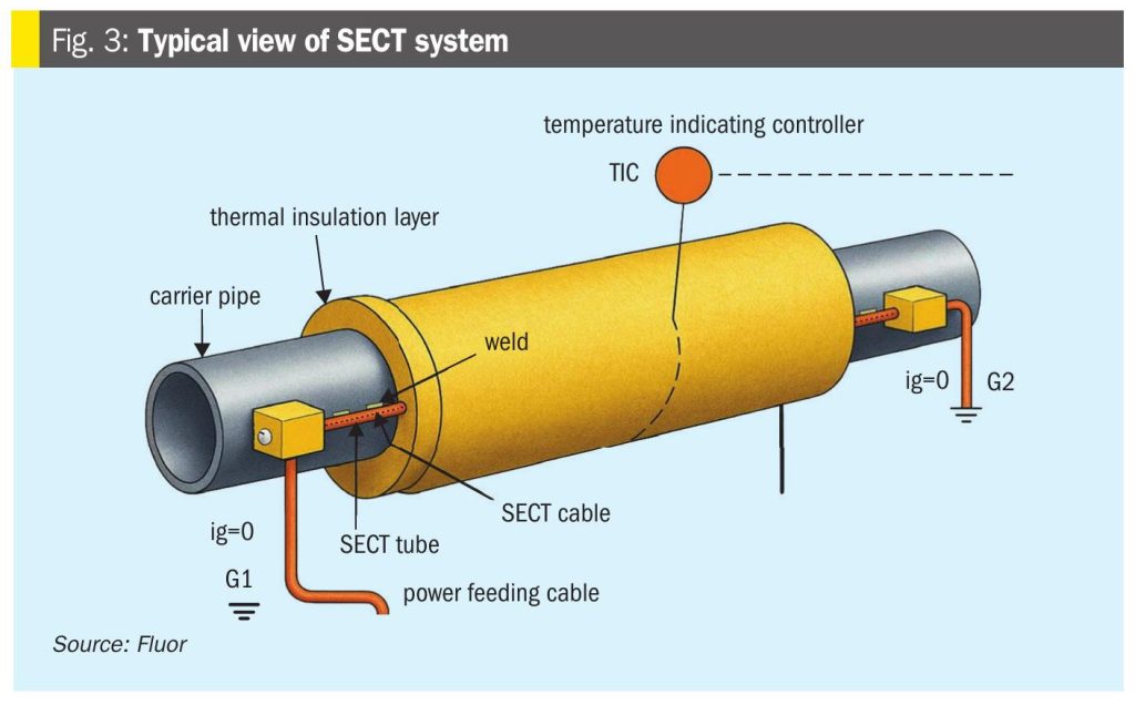
A significant case study incorporated into this article is based on the remelting and heat-management strategy developed for a liquid sulphur transfer pipeline of more than 10 km in a refinery complex. Fig. 3 provides a simplified sketch of the system. Equipped with a specialised thermal management system, the pipeline required a robust design to address the inevitability of sulphur solidification during long-term operation and power outages.

The engineering approach included transient finite element analysis (FEA) to accurately model sulphur heat-up behaviour and predict realistic remelt times, evaluation of temperature profiles along the entire pipeline length, and incorporation of pre-insulated pipe technology to maintain a uniform thermal environment. The study emphasised that sulphur solidifies when temperatures drop below approximately 119°C, and during this phase transition undergoes a volumetric change of about 8 to 9%, creating risks such as void formation, localised overheating during remelt, high internal pressure from thermal expansion, and premature transfer of partially solidified sulphur – all of which can threaten pipeline integrity.

The remelt programme therefore included clearly defined operating envelopes, controlled heat-up rates, and standardised remelt procedures to ensure safe restart under abnormal operating conditions. This case study provides relevant lessons on design constraints, heat tracing philosophy, and the importance of predictive modelling tools for long-distance sulphur transfer reliability.

Design approach

The design of the integrated remelt programme was developed in close collaboration with the thermal management solution provider, ensuring alignment between process requirements and heating system capabilities.

A key element of this approach was the use of transient finite element analysis, which enabled detailed modelling of sulphur heat-up behaviour and temperature distribution across the pipeline, and provided realistic predictions of remelt durations for both fully filled and partially empty conditions.

In parallel, a skin effect current tracing system was incorporated to deliver uniform and controllable heat input along the pipeline, eliminating the operational complexities associated with steam tracing, such as condensate handling. This was complemented by pre-insulated pipeline with isolated supports, specifically designed to minimise thermal bridges and maintain consistent temperature profiles during reheating, thereby enhancing the overall reliability of the remelt process. Table 1 provides the system design parameters that ensure safe operation below polymerisation thresholds while maintaining adequate fluidity for pumping.

Thermal characteristics and remelt risks

Sulphur solidifies at around 119°C and shrinks 8 to 9% in volume when transitioning from liquid to solid. During reheating, this entrapped solid sulphur expands and may generate local pressure surges.

Critical risks identified

Several critical risks were identified during the remelting process, primarily associated with non-uniform phase transition and localised heat transfer behaviour. Voids and packed sulphur can form at elevated sections of the pipeline, while insulation discontinuities near anchors and supports may lead to localised overheating during reheating.

Additionally, the solid-to-liquid transition can result in internal pressure buildup if a continuous molten channel, enabling pressure relief and flow initiation, or a “rat hole,” is not established within the pipeline. These risks highlight the importance of controlled heating strategies and proper thermal design to ensure safe and effective remelt operations

Thus, the remelt objective was defined as: “Generate a molten flow channel (rat hole) through the solid sulphur matrix to relieve pressure and allow progressive melting.”

The remelt limiting conditions and design constraints used to achieve this are defined in Table 2.

Instrumentation included RTDs placed at expected solid plug locations, especially at the highest elevation points to address the risk of void formation and at the lowest elevation points to monitor solid accumulation.

Remelt execution – Controlled heat cycling strategy

A controlled stepwise heat-up and cycling method was used to avoid thermal runaway and prevent premature melting at pipe anchors. The remelting sequence was as follows:

  1. Continuous heating until RTDs reach 80°C.
  2. Heat cycling at 80°C for 20 hours.
  3. Continuous heating until 100°C.
  4. Heat cycling at 100°C for 25 hours.
  5. Continuous heating until 110°C.
  6. Heat cycling at 110°C for 20 hours.
  7. Continuous heating until approaching melting range (115°C–119°C).
  8. Maintain heat for 7-10 hours to stabilise rat hole formation.
  9. Heat cycling again (30 mins on/40 mins off).
  10. Resume continuous heat until sulphur reaches 138°C and pumping resumes.

Total remelt duration: approximately 150 hours, depending on starting temperature and ambient conditions

Outputs and observations of finite element analysis

The FEA simulations modelled the temperature profile in two cases:

  • Case A: Heat-up of a pipeline fully filled with sulphur its remelting.
  • Case B: Heat-up of an empty pipe to model air pockets that may be present at elevated points if sulphur is allowed to solidify.

Key FEA findings

The finite element analysis provided critical insights into the thermal behaviour of the pipeline under different operating conditions. It showed that empty or vapour-filled sections heat up more rapidly than sections filled with sulphur, creating the potential for non-uniform temperature profiles during remelting.

The analysis also highlighted that the presence of voids can lead to localised overheating unless controlled heat cycling strategies are implemented. In addition, temperature lag was observed at pipe supports and anchors due to higher heat losses in these regions, underscoring the importance of careful insulation design and controlled heating to achieve uniform temperature distribution.

Based on FEA results, heat cycling durations were optimised to avoid localised overheating in vapor-filled sections. Fig. 4 shows remelting curves for full and empty sections of the pipeline.

Outcome and learnings

The implementation of the controlled remelt procedure demonstrated significant improvements in operational safety and reliability. By carefully managing the heating profile during phase transition, the risk of pipeline rupture due to internal pressure buildup was effectively mitigated.

The use of predictive modelling ensured uniform heat distribution along the pipeline, minimising the formation of localised hotspots. Furthermore, the standardised remelt sequence proved to be both safe and repeatable, enabling operators to confidently restart sulphur transfer even after prolonged shutdowns.

Key takeaway

The study highlights that without predictive modelling and controlled remelt strategies, long-distance sulphur pipelines remain highly susceptible to plugging and structural failure due to thermal expansion and trapped solids.

Conclusion

The transportation of liquid sulphur over long distances is inherently complex due to its narrow operability window, strong temperature-dependent properties, and phase transition behaviour. Ensuring that sulphur remains in a stable molten state throughout the pipeline requires precise thermal control, robust mechanical design, and disciplined operating practices.

This study demonstrates that these challenges can be effectively addressed through the integration of advanced thermal management systems, particularly skin effect current tracing (SECT), which provides uniform and reliable heat input across extended pipeline lengths. When combined with high-performance insulation systems and carefully engineered pipeline configurations such as optimised slopes, expansion allowances, and maintainability features, the risk of heat loss, solidification, and structural stress can be significantly reduced.

A key contribution of this work is the development and application of a structured remelting methodology, supported by transient finite element analysis. The case study highlights how predictive modelling enables accurate assessment of temperature profiles and remelt behaviour, allowing the design of controlled heat-up procedures that mitigate risks associated with void formation, localised overheating, and pressure buildup. The introduction of controlled heat cycling and the concept of “rat hole” formation further enhance the safety and reliability of pipeline restart operations.

Equally important are the operational practices that underpin system reliability. Continuous temperature monitoring, proactive maintenance of insulation and tracing systems, and strict adherence to start-up and shutdown procedures play a critical role in preventing failures and ensuring long-term performance.

The findings from the presented case study confirm that a synergistic approach – combining advanced design methodologies, predictive thermal modelling, and disciplined operational frameworks – can successfully enable safe, reliable, and continuous transport of molten sulphur over extended distances. These insights provide a practical foundation for the design and operation of future liquid sulphur pipeline systems, supporting improved safety, operational resilience, and overall system efficiency.

Latest in Technology

Axens signs agreement with Egyptian Refining Company

Axens says that it has strengthened its collaboration with Egyptian Refining Company (ERC) via a long-term agreement aimed at maximising asset value and supporting ERC’s evolving needs in product supply, digital transformation, and refinery performance optimisation. Under the agreement, Axens will use its integrated portfolio of technologies, equipment, catalysts, and services to support ERC’s operational, economic, and sustainability objectives.

Travertine processes Ariane phosphate samples

Arianne Phosphate has provided samples of its phosphate concentrate for processing at Travertine’s facility in Boulder, Colorado, US. Pilot scale testing was successfully performed, demonstrating proof of concept on the process and production of a high-quality purified phosphoric acid (PPA). The Travertine process captures and recycles over 95% of the sulphur used in the process of making PPA, providing a virtually closed loop system. The PPA produced using the process met specifications required for both LFP batteries as well as fertilizers. The companies have begun work to advance the PPA demonstration plant in Quebec’s Saguenay-Lac-Saint-Jean region, working with potential partners as well as end-users of the product.