Sulphur 423 Mar-Apr 2026
20 March 2026
The secrets of successful sulphur strategies
SULPHUR RECOVERY
The secrets of successful sulphur strategies
Efficient sulphur recovery is essential for modern refineries to meet stringent environmental regulations and support sustainability goals. Debopam Chaudhuri, Pranay Veer Singh and Vaneet Garg from Fluor examine the key design considerations, smart design strategies and flexible sulphur block configurations that are essential in achieving an overall optimised design. Together, these strategies enhance efficiency, reduce emissions, improve reliability, and provide flexibility for changing crude qualities, ensuring compliant and economically robust refinery operations.
Sulphur recovery is a cornerstone of modern refining and gas processing, driven by stringent environmental regulations and the growing need to minimise emissions. Compliance with these regulations is not optional, it is a critical requirement for refineries and gas plants to operate responsibly and sustainably. Beyond regulatory obligations, efficient sulphur management plays a vital role in protecting air quality, reducing environmental impact, and supporting global sustainability goals.
This article explores strategies for integrating three key units: the amine regeneration unit (ARU), sour water stripper (SWS), and sulphur recovery unit (SRU) – collectively forming the sulphur block. Each of these units performs a distinct yet interconnected function. The ARU regenerates the circulating amine by removing absorbed acid gases such as hydrogen sulphide (H2S) and carbon dioxide (CO2) from rich amine streams to generate lean amine. The SWS treats sour water streams, stripping ammonia (NH3) and H2S to produce acid gas for further processing while generating stripped sour water for reuse. These streams converge at the SRU, where the Claus process converts H2S into elemental sulphur, eliminating SOx emissions, ensuring compliance with emission standards and minimising environmental impact.
Efficient sulphur management is achieved through the integration of these three units, which collectively form the backbone of refinery operations for sulphur management. This synergy not only optimises sulphur recovery but also reduces energy consumption and enhances reliability across the entire process chain. By converging these systems, refineries adopt a holistic approach to sulphur handling, effectively reducing operational bottlenecks and improving overall plant efficiency. Such integration is critical for meeting sustainability goals while maintaining economic viability in an increasingly competitive industry.
As environmental standards become more stringent and the demand for cleaner fuels grows, the importance of robust sulphur recovery systems will continue to rise. While the need to be more efficient in operation and design will continue to mandate a ‘leaner’ sulphur block for the facilities. The strategies discussed in this article aim to transform sulphur recovery from a compliance-driven necessity into a value-added process that supports operational excellence and long-term profitability.
The sulphur block
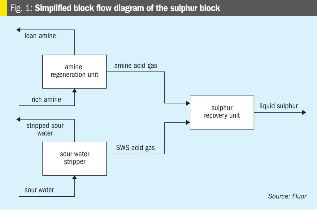
The sulphur block comprises three primary units, the ARU, SWS, and SRU, working together to recover sulphur and meet environmental norms. It is a critical configuration in refinery operations, designed to efficiently manage sulphur compounds and ensure compliance with environmental standards. Each unit plays a distinct yet interconnected role in the overall sulphur management process. Fig. 1 shows the very high level interaction between these three units.

Amine regeneration unit
In refinery hydroprocessing units, hydrogen sulphide is removed from hydrocarbon streams using amine solvents, most commonly a hindered tertiary amine such as methyldiethanolamine (MDEA). The amine solution, now rich in absorbed H2S, is regenerated in the ARU in a regenerator column, releasing H2S gas and producing lean amine for reuse. This closed-loop system enables continuous H2S removal from multiple refinery streams. The liberated H2S-rich gas is routed to the sulphur recovery unit.
Sour water stripper unit
Various process units generate sour water containing dissolved H2S and ammonia. The SWS unit strips these contaminants, producing an acid gas stream rich in H2S and NH3. This stream is also sent to the SRU. The presence of ammonia adds complexity to SRU design, as it can lead to undesirable byproducts if not properly managed, thus requiring additional check points in designing of the sulphur block.
Sulphur recovery unit
The SRU processes combined H2S-rich gases from the ARU and SWSU, converting H2S into elemental sulphur for storage, transport, or sale. Most typically the modified Claus process is implemented to convert the H2S to elemental sulphur, complemented by a reduction-absorption-regeneration based (amine based) tail gas treatment unit (TGTU). The modified Claus process implements the thermal stage followed by a catalytic stage for the conversion of H2S to elemental sulphur. A sulphur degassing block to purify the product sulphur, and a thermal oxidiser stage to incinerate any unrecovered H2S completes the configuration of the SRU.
Together, the ARU, SWSU, and SRU form a critical subsystem in refinery operations. By integrating these units into a cohesive sulphur block, refineries streamline operations, minimise bottlenecks, and enhance overall efficiency. This synergy not only ensures regulatory compliance but also supports sustainability objectives, making the sulphur block an essential component of successful refining operations.
Understanding synergy strategies
Design basis for the sulphur block
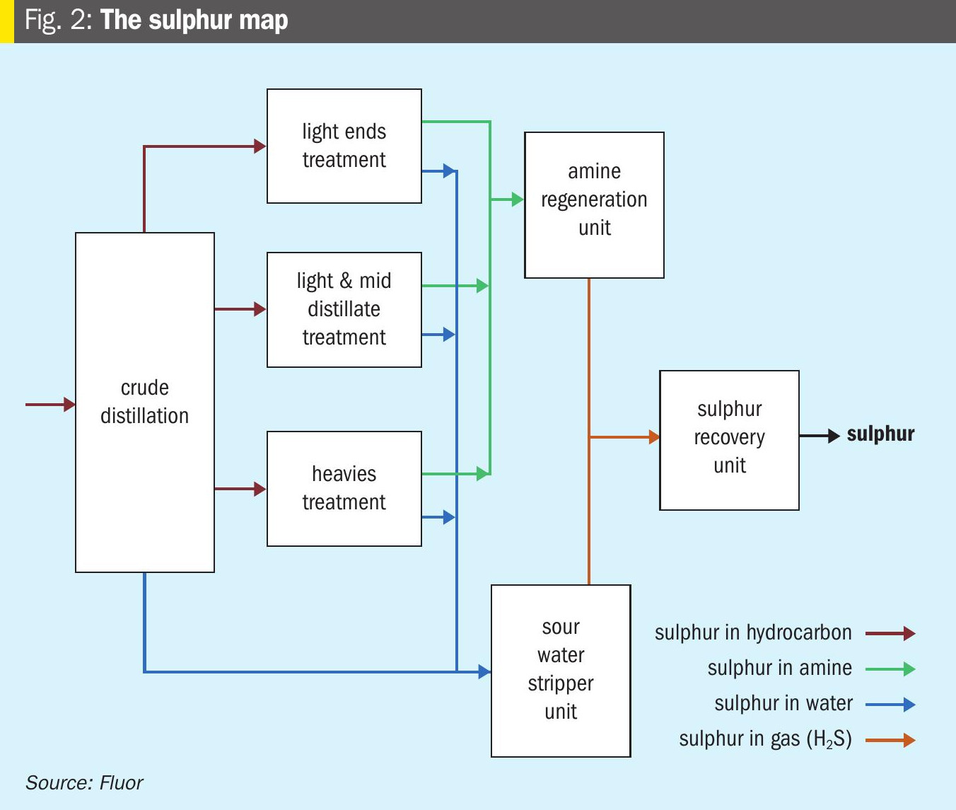
The sulphur block in a refinery is designed based on the amount of sulphur present in the crude oil and how it is distributed across different process streams. Correctly estimating this sulphur load is essential for determining the optimum capacity (size) of the ARU, SWS and SRU. At the same time, it is important to understand the overall refinery operational reliability for the design of the sulphur block – in particular the train configurations for each of the units. Fig. 2 shows a bird’s-eye view of the sulphur movement across various processing units in the refinery starting from the crude oil and ending up finally in the SRU.
There are two main design approaches: backward integration and forward integration.
Backward integration starts with the SRU, calculating its capacity based on total sulphur recovery needs. From there, the ARU and SWS capacities are determined. This approach ensures compliance with environmental regulations and sulphur recovery targets.
Forward integration begins with upstream process units, estimating acid gas and sour water generation to size ARU and SWS first, then the SRU. Forward integration often results in oversized equipment because peak loads in upstream units rarely occur simultaneously – a non-coincident peak scenario.
An optimised design balances these approaches, considering variations in upstream processes to avoid unnecessary costs while maintaining reliability. Proper integration of these units ensures efficient sulphur handling, reduced emissions, and sustainable refinery operations.
A simple case study data is shared on how the sulphur load of a refinery is estimated using the backward integration method to determine the SRU capacity. This case study considers a refinery expansion project to increase its crude processing capability to 15 million t/a. The design case of the refinery operation with respect to the maximum sulphur load is based on processing a mix of high sulphur crude (Basra Light) and low sulphur crude (Bonny Light) and generating a mixture of fuels and hydrocarbons for downstream processes. A mix of Basra Light and Bonny Light in a ratio of 80-20 is considered for sulphur balance as the worst feed with respect to the sulphur content. Based on the actual mathematical sulphur recovery capacity (971 t/d), the real capacity of the sulphur recovery may be selected by adding a margin. The margin typically is 10% or 15% over the calculated plant capacity thus the total expected plant capacity would have been 1,100 t/d in case this would have been a greenfield refinery project.
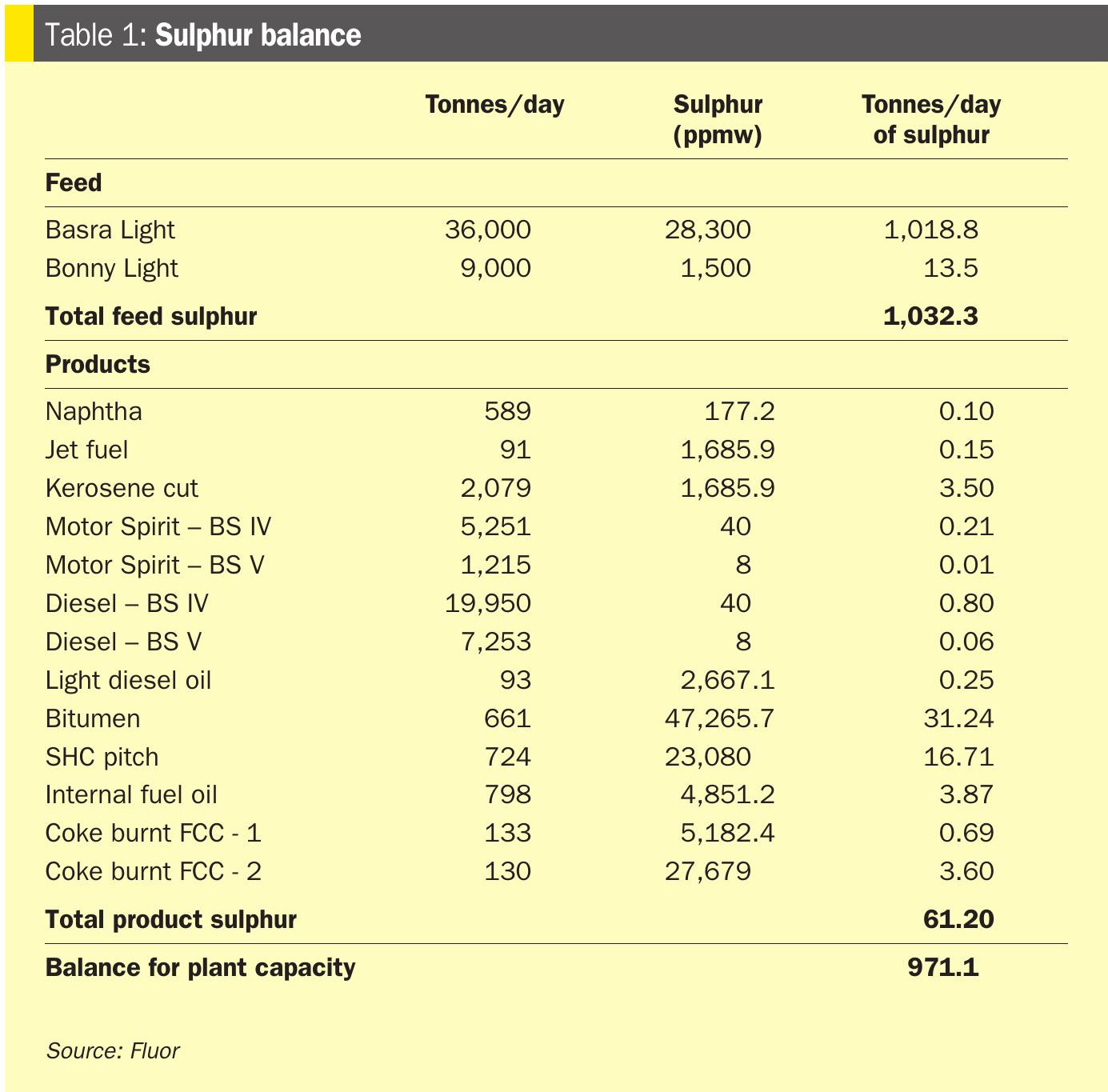
Since the example cited in Table 1 is for a refinery revamp, the new sulphur plant capacity depends on the existing and available sulphur handling capacity of the refinery. And this refinery already had an installed total sulphur handling capacity of 495 t/d (two non-identical trains – an old 195 t/d train and a more recent 300 t/d train), thus the additional sulphur handing capability that was demanded after the revamp was 476 t/d. Taking an additional design margin of 10%, the required capacity is fixed at 520 t/d. But while considering the SRU design capacity the old train was not considered and hence the required capacity was finalised at 720 t/d. And to accommodate operational variations, the new SRU train configuration was fixed at 2 X 360 t/d. This configuration allowed for maximum flexibility in the refinery operation and had minimum impact on the refinery throughput with one SRU train becoming unavailable.
The new ARU and SWSU capacities were based on the sulphur load and considering the additional details from the various processing units. For the ARU, the peak simultaneous sulphur load and the amine circulation rates were considered for the plant capacity, considering non-concurrent design loads always lead to overcapacity. And similarly for the SWS unit, the sour water stripping load was based on the concurrent sour water effluent loads from the process units.
Determining the SRU inlet pressure
The inlet pressure of the sulphur recovery unit is an important design factor that influences both process performance and general equipment size of the unit. This pressure is mainly controlled by the operating conditions of upstream units such as ARU and SWS unit. Choosing the right pressure ensures smooth operation and proper integration within the sulphur block.
Higher SRU inlet pressure has certain benefits and drawbacks. On the positive side, it reduces the size of SRU equipment, which lowers capital costs and saves space. However, it also increases the demand for low-pressure steam in the ARU and SWS reboilers, leading to higher energy consumption. On the other hand, operating at lower pressure reduces steam requirements but results in larger SRU equipment, which can increase costs and footprint. Hence it is imperative that the units within the sulphur block synergise to find the sweet spot of plant operation.
Industry practice recommends a column-top pressure of around 1 barg as it balances energy efficiency and equipment sizing, reducing steam demand while maintaining operability. Finalising this pressure requires careful consideration of upstream conditions and process constraints to ensure reliable, cost-effective, and efficient sulphur recovery.
This pressure also plays an important role in revamp projects which translates to very small increase in sulphur loads which does not demand any major revamp or modification in existing unit designs. A small increase in sulphur operation loads can be met by making small changes in the SRU, and the higher process gas then would translate to slightly higher pressure drops in the unit, demanding a higher unit battery limit pressure. In such cases the operating pressures of the ARU and SWSU columns are increased to the limit of their operations, allowing a higher battery limit pressure at SRU.
SRU capacity control
Managing capacity in a multi-train sulphur recovery unit setup is crucial for maintaining stable and efficient operations in refineries. Typically, these configurations include several SRU trains working in parallel to handle varying acid gas loads. The muti train concept is mainly to manage the refinery operations such that the availability of the SRU is maintained and planned shutdowns of the SRU are linked to planned turnarounds of the overall refinery.
Under such configurations, all but one SRU train run at a fixed load, with only one train ‘floating’ with the acid gas header pressure. There is a master pressure measurement and controller on the main acid gas header. The signal form this pressure controller is fed to one of the flow controllers of the SRU acting as the master – cascade control loop, such that all changes in pressure due to variations in the acid gas generation rate from the upstream unit is managed by fluctuating the acid gas flow into that train of SRU. The other trains operate on a fixed flow, while the flexibility in design is available allowing operator to choose any train of the SRU as the ‘floating’ train. This is applied for both the acid gas system – amine acid gas from the ARU and SWS acid gas from the SWS unit. This floating train absorbs acid gas fluctuations, but robust control logic and alarms are essential to prevent overload. This approach ensures that most trains run under steady conditions, reducing complexity and improving predictability (Fig. 3).
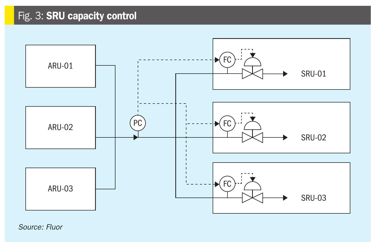
The floating train plays a key role as a buffer. It adjusts automatically to changes in acid gas flow from upstream units – ARU and SWS unit. By responding to header pressure, it absorbs fluctuations without disturbing the fixed trains. However, this flexibility comes with a trade-off – only the floating train is exposed to operational variations, a small overall variation enunciates a larger variation as only one train gets exposed to the entire deviation. This makes the floating train more susceptible to process upsets and requiring robust control systems.
This method strikes a practical balance between reliability and adaptability. It prevents all trains from continuously adjusting, which could lead to instability and higher operator interventions. Effective implementation requires precise control logic and monitoring to avoid overloading the floating train. When applied correctly, this strategy optimises sulphur recovery, minimises downtime, and ensures smooth operation in multi-train SRU configurations, with minimum operator involvement.
ARU and SRU – common solvent
Using a common amine solvent for both the amine regeneration unit and the sulphur recovery unit is a practical possibility as theoretically the amine-based solvent used in the ARU and the TGTU section of the SRU are both designed to selectively absorb H2S from the acid gas streams. And using a common solvent definitely offers significant potential for cost savings and operational efficiency. By standardising the solvent across these units, refineries can simplify processes and reduce complexity in handling and storage.
One of the major benefits of this approach is the possibility of using a shared regenerator, which minimises equipment duplication and lowers capital expenditure, while adding a little complexity in the piping system to cover for both the amine system. Additionally, managing a single solvent system reduces the need for multiple tanks, pumps, and associated infrastructure, leading to streamlined operations and reduced maintenance requirements. This is a more practical approach as the amine tank is typically used only for inventorying and solvent make-up periods, and is mostly not used or kept empty.
However, implementing a common solvent system is not without challenges. The main challenge is linked to the differences in lean/rich loading for the ARU and the TGTU of the SRU. The design basis for the amine solvent system for the ARU and TGTU differs due to variations in rich and lean amine loading. The ARU typically handles higher acid gas concentrations, thus the amine design in most cases are rich-pinched; while the SRU requires a much leaner lean solvent concentration and precise control to ensure optimal sulphur recovery, and the design of the amine solvent system is lean-pinched. And thus to achieve the required leanness in many TGTU designs the amine solvent has certain additives or is formulated for an efficient design – requiring lesser steam for stripping.
Although it is not impossible to design a common amine solvent, these differences in design concepts must be carefully addressed during design to avoid operational constraints. Successful adoption of this concept requires thorough evaluation of process conditions, solvent characteristics, and regeneration requirements. When properly engineered, this strategy can deliver substantial economic and operational benefits without compromising system performance or reliability. For example, even when the steam demand for the common regenerator is higher than the added steam demands for the ARU and TGTU regenerator, there are benefits which might compensate for this higher operation and capital costs.
SWS configuration
Optimising the sour water stripper design is critical, especially when processing high-nitrogen crudes and/or when the refinery is designed to operate with a diverse crude slate varying from low nitrogen to high nitrogen. In such cases, a two-stage SWS configuration offers significant advantages by efficiently separating hydrogen sulphide and ammonia from sour water streams. This approach enhances operational flexibility and reduces downstream challenges in sulphur recovery and SRU designs.
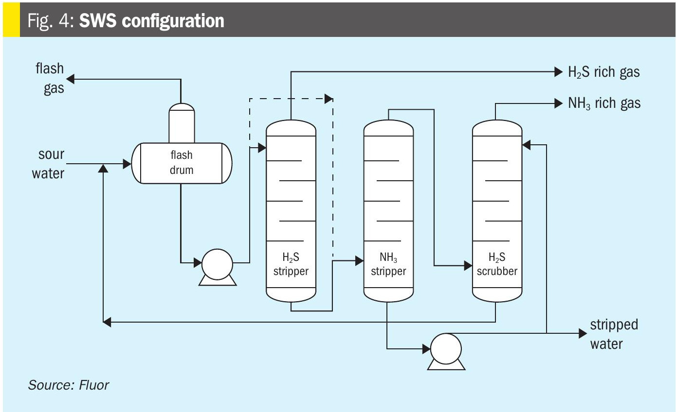
Refineries handling high nitrogen crudes can yield a total acid gas stream – mixed acid gas stream from ARU and SWSU – containing very high proportions of NH3, such that processing of such gas streams becomes a challenge in the Claus section of the SRU. One key opportunity for the two-stage SWS system as shown in Fig. 4 is the fact that it generates an NH3 stream separate to the H2S stream.
Instead of routing ammonia through the Claus reaction furnace, it can now be directed straight to the incinerator. This bypass strategy simplifies the Claus section, minimises operational risks, and improves reliability. Additional design modifications in the incinerator are necessary to manage the potential of high NOx problems due to burning high amounts of ammonia. The simplest solution for such issues is to include a selective catalytic reduction (SCR) unit and use a slip stream of the same ammonia in a SCR to manage the NOx. Alternatively, the recovered ammonia can be utilised as a valuable byproduct in certain applications, further enhancing process economics, if the market is available, thus even increasing the economic viability of the overall sulphur block.
The two-stage SWS design, shown in Fig. 4, exploits the differences in solubility and affinity for water between H2S and NH3. H2S is considerably less soluble in water than NH3. Therefore, the first column (the H2S stripper) operates at higher pressure so that almost the entire H2S load is removed, leaving NH3 in the aqueous phase to be treated in the second column (the NH3 Stripper). The second column must operate at much lower pressure to release NH3 from the aqueous phase. As shown in Fig. 4, an additional H2S scrubber column may be included to limit H2S slip into the NH3-rich gas stream, primarily to reduce SOx emission issues in the downstream SRU incinerator.
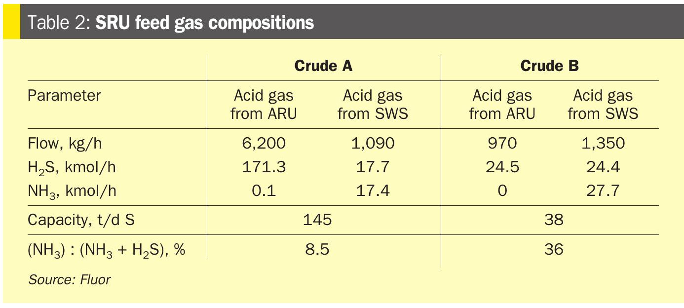
Case study data are presented for a refinery designed to operate on a diverse crude diet: Crude “A” – high sulphur, low nitrogen; and Crude “B” – low sulphur, high nitrogen. Table 2 shows how varied the acid-gas composition can be if a conventional single-stage SWS unit is used. The design implemented in this case study uses a two-stage SWS unit, with an SCR installed in the SRU incinerator. Fig. 5 shows the SRU design and how it manages the H2S- and NH3-rich streams.
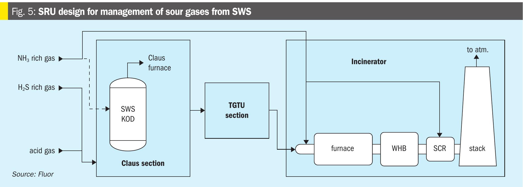
The H2S-rich stream is routed to the front end (the Claus section) of the SRU for sulphur recovery, while the NH3-rich stream is routed to the rear of the unit to the thermal incinerator, where it is burned off and released to the atmosphere. To meet NOx emission limits, a portion of the NH3-rich stream is routed through the catalytic converter (SCR).
The two-stage SWS can also be operated as a single-stage unit, as shown by the dashed line in Fig. 4, allowing refiners to manage both low nitrogen and high nitrogen crudes with the same installed unit. By adopting a two-stage SWS design and optimising NH3 management, refineries can achieve better sulphur recovery performance, reduce maintenance issues, and improve compliance with environmental standards.
Sour water from the SRU
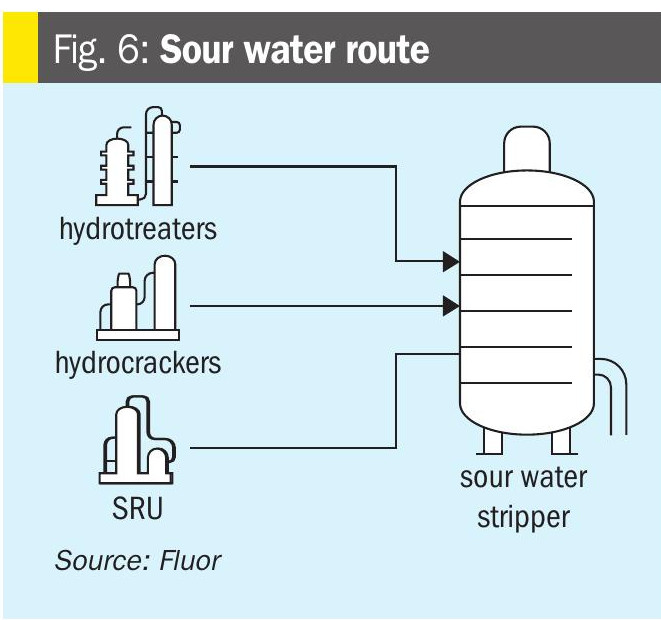
The major sources of sour water are the refinery’s secondary process units — the hydrotreaters, the hydrocrackers, and the thermal crackers such as the FCC and DCU. Small sour-water streams are also generated by the SRU and the ARU, and these contribute to the facility’s overall sour-water balance (Fig. 6).
During early design, the sour-water flows from the SRU and ARU may not be available for finalising the SWS unit capacity. Therefore, it is prudent to use reference project data or other databases to estimate the sour-water volumes produced by the SRU and ARU. Although these streams are small in volume, they are significant to the overall sour-water system design: they are typically low in H2S and have very low to negligible NH3, but can represent roughly 10% of total sour-water generation, thus impacting the hydraulic design of the overall sour water system.
For design optimisation, it is essential to account for the normal purge rate from the SRU rather than peak values. Multiple sources generate sour water in the SRU, but many are intermittent. The routine sour-water purges from the quench-water system and the regenerator-reflux system of the TGTU should be included in the normal sour-water balance. Overestimating peak flows by considering the intermittent and emergency sour water flows can lead to oversized sour water stripper units, increasing capital costs without adding real operational benefits. By focusing on typical purge conditions, refineries can achieve a balanced design that ensures reliability while minimising unnecessary investment.
Lean acid gas system
Handling lean acid gas streams, particularly those with high CO2 content, requires a specialised approach to maintain efficiency and reliability. These streams typically originate from renewable unit integrations or gasification processes, where acid gas composition differs significantly from conventional sources. The challenge lies in the low H2S concentration, which impacts sulphur recovery performance in standard SRU configurations.
A practical solution is to design a separate train configuration for the ARU, SWS, and SRU dedicated to lean acid gases. This segregation ensures optimised treatment without affecting conventional trains.
A revamp case study is presented in which, for cost-effectiveness, only one of the existing SRU trains was upgraded for lean-gas handling by incorporating design enhancements to achieve high-level oxygen enrichment. Alternatively, in the absence of oxygen enrichment, fuel-gas cofiring provides a route to manage lean gas in the SRU. These modifications improve combustion stability and sulphur recovery efficiency despite the low H2S content.
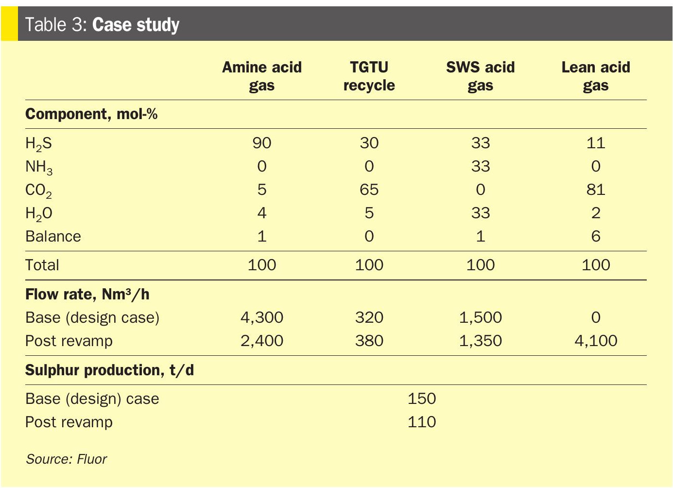
The case study in Table 3 shows that, after the revamp, coprocessing all the lean gas with some rich acid gas from the existing ARU and SWS increases the hydraulic acid-gas load while producing lower sulphur quantities and reducing sulphur handling requirements. Therefore, high-level oxygen enrichment was included in the design to manage lean feed-gas processing in the SRU. Implementing oxygen enrichment allowed the unit to operate with the revised feed-gas composition even when processing appreciable quantities of lean acid gas. The advantages of implementing high level oxygen enrichment were:
- Minimum revamp needed – existing equipment (burner and furnace) replaced in situ and no impact on plot area
- Operational flexibility – unit able to operate over a wide range of feed gas compositions by managing the level of oxygen enrichment.
- No impact to the unit beyond the existing Claus furnace – operating capacity post revamp well below design values.
By isolating lean acid gas processing and applying targeted upgrades, refineries can avoid overdesigning all SRU trains while maintaining operational flexibility. This approach minimises capital expenditure, enhances energy efficiency, and supports integration with emerging renewable and gasification technologies.
Key takeaways
Designing and operating sulphur management systems requires a holistic approach to achieve efficiency, compliance, and flexibility.
First, optimised design considerations are essential to avoid overdesign, which can lead to unnecessary capital costs and operational complexity. Implementing rational strategies ensures that systems are right sized for actual process requirements.
Second, integrated environmental compliance plays a critical role in minimising emissions and pollutants. Proper synergy between units reduces SO2 emissions, NH3 slip, and water contamination, helping refineries meet stringent environmental regulations and avoid penalties.
Third, enhancing reliability through strong interface management prevents cascading upsets across interconnected units. Robust control strategies and communication between units are key to maintaining stability.
Finally, strategic flexibility for crude variability ensures adaptability to changing feedstock compositions and rate swings. Well-defined interfaces allow quick adjustments without compromising compliance or profitability.
These principles collectively support sustainable operations, cost efficiency, and regulatory adherence, making them indispensable for modern refinery design and operation.