Nitrogen+Syngas 398 Nov-Dec 2025

24 November 2025
Cracking it back: Hydrogen from ammonia
Air Liquide is developing a new ammonia cracking technology based on its proven steam methane reforming (including SMRX™) technology, which introduces a heat exchange concept to cut energy use, lower environmental impact, and potentially eliminate steam export. Leveraging extensive SMR design expertise, a robust R&D programme, and an industrial-scale NH3 cracking pilot plant, it aims to rapidly mature all technology blocks and deliver safe, reliable, and customisable low-carbon hydrogen solutions to meet growing demand.
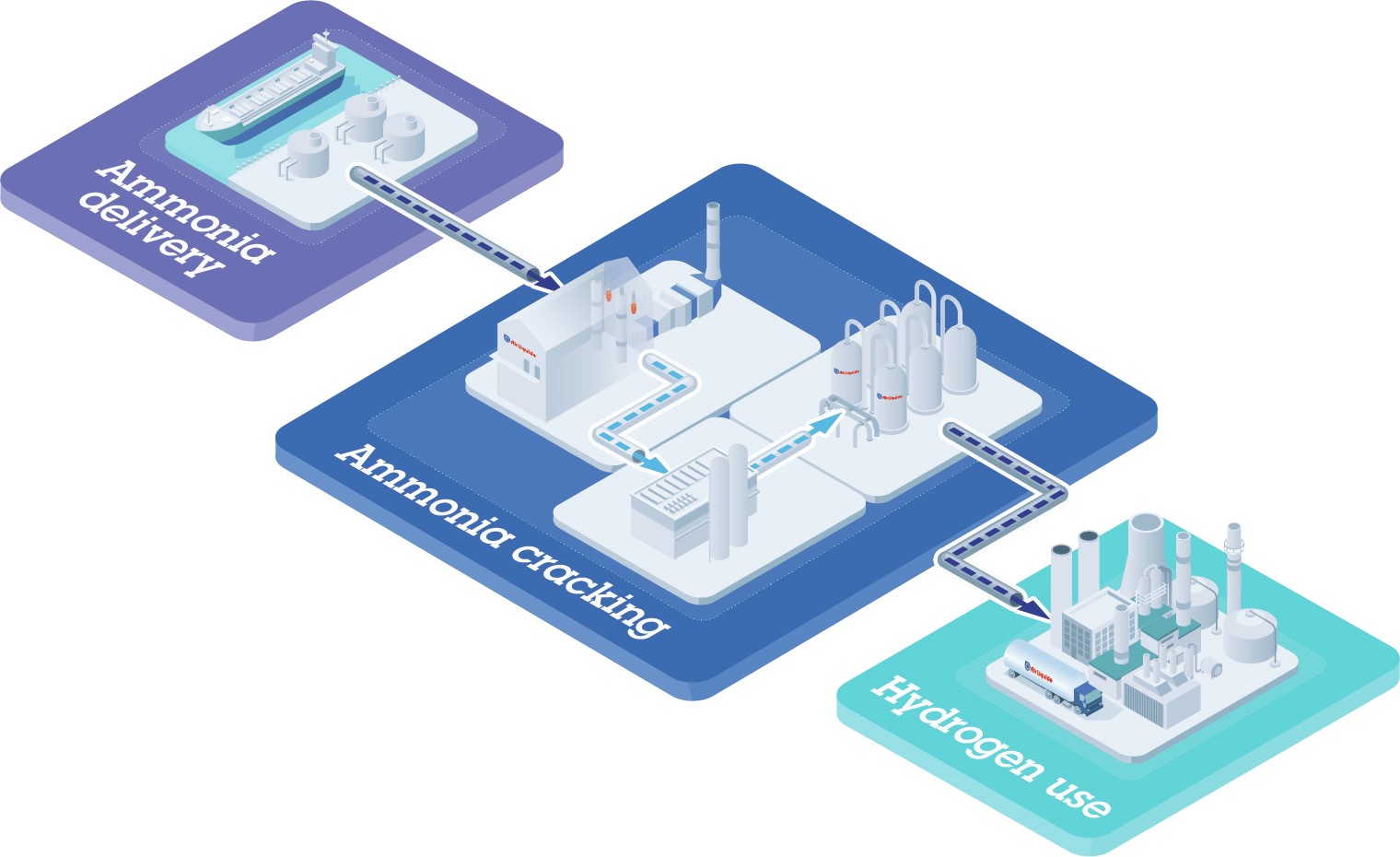
Ammonia, a widely known chemical, is emerging as a promising low-carbon hydrogen carrier due to its high energy density, its ease of liquefaction as well as its potential to ensure a low-carbon footprint throughout its entire value chain. The process of ammonia cracking, which releases hydrogen from ammonia, plays a crucial role in enabling the utilisation of ammonia as a hydrogen and energy carrier. Air Liquide is committed to decarbonise the industry by providing its customers with safe, efficient and reliable solutions for a sustainable future1.
Inspired by steam reforming (SMR)
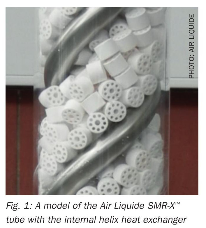
Air Liquide’s extensive experience in handling and delivering diverse molecules, combined with its expertise in the construction and operation of steam methane reformers (SMR), positions it as a leader in ammonia cracking solutions. The capacity for SMRs can be up to 230,000 Nm3/h of pure hydrogen. The SMR technology has been further developed, resulting in the SMR-X™ technology. Developed in the mid-2010s to promote decarbonisation, SMR-X™ introduces a heat exchange concept, leading to energy savings, a reduced environmental footprint, and the potential for zero steam export2.
This technology, proven at large scale, uses a heat exchange within the reforming tube. Hot reformed gas is diverted by 180° at the end of the reformer tube and flows counter-current to the feed flow within a helix-like tube. The helix is within the reformer tube, surrounded by the catalyst, providing energy for the reforming reactions. This lowers reformed gas exit temperatures and allows flexible steam production, even steam-free operation. The principle is illustrated in Fig. 1.
By taking advantage of its SMR-X™ technology, Air Liquide decided to develop a state-of-the-art ammonia cracking solution. The fundamental principles of heat exchange and flexibility of steam production have been transferred in order to benefit from improved energy efficiency and to be able to design crackers without steam export. By adopting this referenced technology, Air Liquide’s ammonia cracking solution guarantees optimal performance and reliability.
Air Liquide ammonia cracking technology development
General overview
The basic layout of Air Liquide’s ammonia cracking technology is illustrated in Fig. 2.

Ammonia conditioning: The ammonia feedstock is processed to remove unwanted components and conditioned to the appropriate pressure and temperature.
Pre-cracker (optional): In some configurations, a partial conversion of ammonia into hydrogen and nitrogen occurs in dedicated equipment, allowing for additional energy recovery.
Ammonia cracker: The primary conversion of ammonia into hydrogen and nitrogen takes place in a radiative furnace using SMR-X™ technology.
Cracked gas cooling and steam production: The cracked gas is cooled, and some of the steam generated is used as a heat transfer fluid in the process.
Hydrogen purification: The cracked gas is purified to achieve the desired hydrogen purity.
To maximise efficiency, a flue gas waste heat recovery system utilises energy from the main cracker’s flue gas. Unconverted ammonia from the purification stage is recycled back to the first step. To close the heat balance, a trim fuel is needed. Air Liquide can offer solutions with different trim-fuel depending on customer requirements and local availability.
Flexibility of the technology
Recognising the plurality of customer needs in terms of hydrogen quantity, pressure and use, such as for chemical processes, combustion or pipeline injection, the Air Liquide ammonia cracking process is flexible. It is adapted to the specificities of each project while meeting local regulations and offering an optimised total cost of ownership (TCO). The capacity range is up to ~500 kNm3 /h of pure hydrogen at a purity up to 99.999% and up to 40 barg without the need for a costly hydrogen compressor.
In addition to the fuel stream derived from the off-gas of the pressure swing adsorption (PSA), an ammonia cracker requires an additional fuel source called trim fuel. The choice of the trim fuel can be adapted to the specificities of each project. For example, the Air Liquide process can self-produce its own trim fuel or utilise an external fuel source.
The type of trim fuel has a significant impact on the ammonia consumption. For example, when the cracker self-produces its own trim fuel, (i.e. cracked gas) or utilises feedstock ammonia trim fuel, a specific ammonia consumption as low as 7.2 kg NH3 / kg H2 can be achieved. If the trim fuel is an external fuel, (i.e. natural gas, hydrogen) the specific ammonia consumption is significantly reduced.
Thus, the use of an external trim fuel can be particularly advantageous depending on the cost difference between this trim fuel and ammonia. Also, the carbon intensity of the potentially external fuel needs to be regarded. Nevertheless, whatever the fuel chosen, SMR-X™ technology makes it possible to achieve a thermal efficiency of at least 97%.
State-of-the-art and development needs
Some ammonia crackers were developed decades ago for metallurgical applications, electronics and for the niche market of heavy water production. The integration of these ammonia crackers in the whole production process of heavy water, for example, leads to process scheme layouts that are not fitting for the production of low carbon hydrogen by ammonia cracking.
Therefore, the technological blocks implemented in those ammonia cracking processes are not suitable for the development of large capacity units. Ammonia cracking is a new process. In particular, the following items are needed:
- a new generation of catalysts;
- metallic materials resistant to nitriding while minimising manufacturing cost;
- low NOx burners to meet today’s emission regulations;
- design margins to account for degradation phenomena to meet safety and reliability requirements.
Although there are many similarities between the SMR process and the ammonia cracking process, it is not possible to directly use the SMR technological blocks. Therefore, the ammonia cracking technology development strategy is based on:
- Air Liquide’s long experience in the design, engineering and operation of SMR;
- an extensive R&D programme;
- an NH3 cracking pilot plant at an industrial scale.
Strategy to rapidly reach full commercial maturity
Innovation is at the core of Air Liquide4. In 2021, Air Liquide started its technology development based, among other things, on an assessment of the maturity of the technological blocks using the technology readiness level (TRL) scale5. It is essential to have access to reliable data. Fig. 3 describes the development strategy for the specific technological blocks of key interest. For each of them, development pathways have been defined to ensure that Air Liquide’s ammonia cracking process will reach TRL level 8 (system complete and qualified) in 2025.
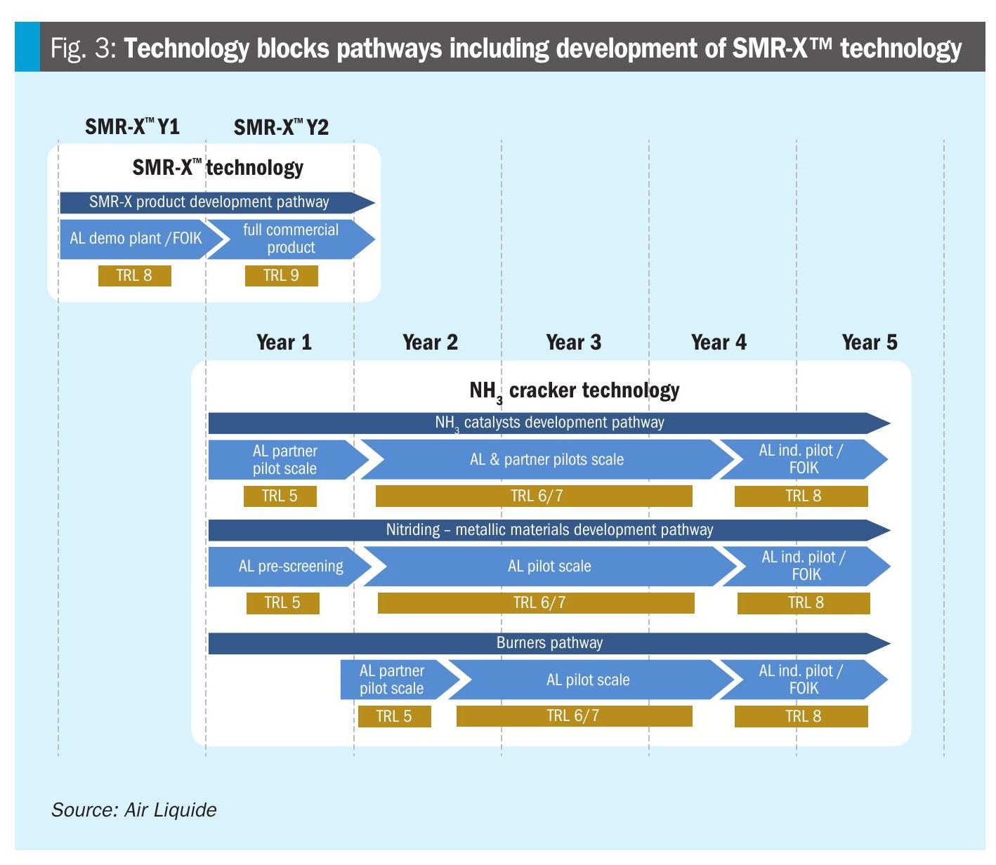
The technological blocks concerned and how they are addressed in various pilot plants as described below:
NH3 catalysts
The challenge for catalysts is to minimise the splitting energy while ensuring good conversion. The related pilot at technical scale allows the testing of NH3 splitting catalysts available on the market. This pilot operates with the full pellet size, instead of crushed catalyst or powder, and under representative operating conditions. In long-term tests, the lifetime of the catalysts can be assessed, also with respect to impurities in the ammonia feed.
Selection of metallic materials for critical equipment
Air Liquide understands in depth the impact of the nitriding phenomenon on commercial alloys. The related pilot was launched at an early stage and is focusing on the impact of the nitriding phenomenon on metallic materials under the conditions targeted for the operation of future commercial crackers. These insights are instrumental in selecting the most economic but still suitable materials for heat exchangers and the cracking tubes, also taking into account mechanical properties. Further, the results validate material degradation models.
Burners
The possibility to use different trim fuels is an important attribute of the Air Liquide ammonia cracking process. However, the choice of the trim fuel influences the quantities of NOx and N2 O generated and the extent of deNOx technologies. In order to ensure the technical feasibility of using different fuels, Air Liquide has early launched commercial burner tests in one of its R&D pilots. These tests are described in detail in reference 6.
PSA
Air Liquide adapted its proprietary PSA technology to purify reforming gases to ammonia cracking by optimising adsorbent materials and cycles to optimise hydrogen yield. In one of its proprietary R&D pilots, it is demonstrated how the PSA manages low ammonia levels in the feed.
Modelling, design and sizing tools
Air Liquide´s dual experience (design and operation) is capitalised in various proprietary design and sizing tools. These tools have been developed both on the basis of substantial R&D work and on the integration of data returned by the operation of the global Air Liquide SMR fleet.
These tools have been adapted to the new ammonia cracking process. For example, the team works with kinetic data of new ammonia splitting catalysts but also utilises three-dimensional CFD (computational fluid dynamics) simulations to model industrial furnaces. In order to do so, data close to the industrial operating conditions are required, which is produced not only but especially by the industrial-scale pilot unit located in Antwerp.
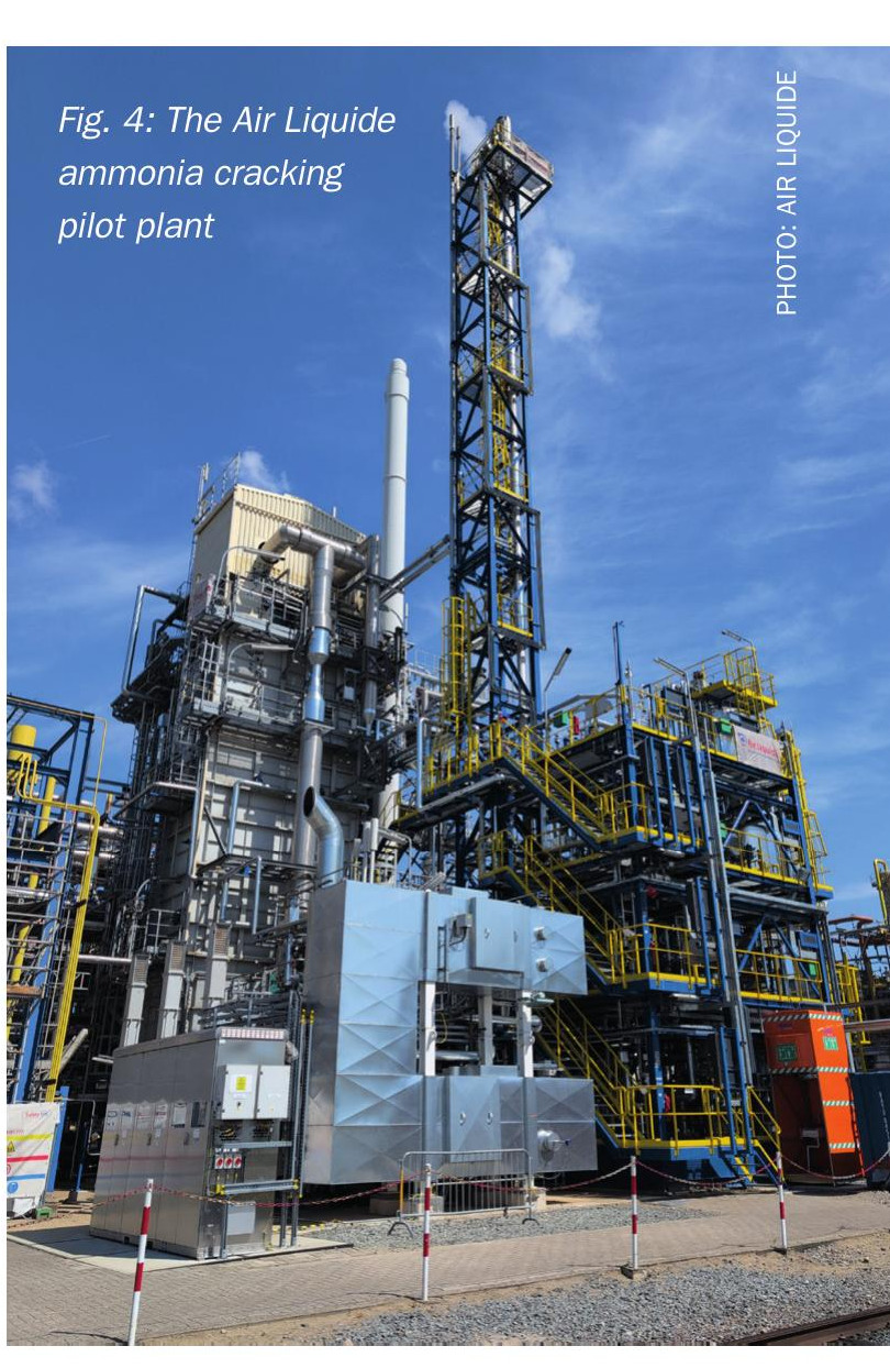
Challenges addressed by the industrial-scale NH3 cracking pilot plant
A special focus in the Air Liquide technology development is the industrial-scale ammonia cracking pilot plant in Antwerp, Belgium, which was announced in 20237 . This pilot plant is the cornerstone of the development strategy; its design and scale validate the performance of all the main technological blocks used in the future commercial crackers and will provide essential data for the calibration of multi-scale design and sizing tools. The experience accumulated by the engineering teams during the construction, commissioning and start-up phases is instrumental to optimise execution strategies for future projects around the world. Furthermore, this pilot plant is a powerful tool for demonstrating the safe operation of ammonia cracking technology at scale, building confidence among stakeholders and regulatory authorities. The pilot plant is depicted in Fig. 4 and comprises several full size reformer tubes of different materials and full size burners. This allows testing of multiple commercially available catalysts at the same time. It further comprises all essential elements of an ammonia cracking plant, from ammonia vaporisation to cracked gas cleaning. It is equipped with plenty of instrumentation and sampling points to gather a maximum amount of data. Furthermore, it is equipped with a NOx reduction unit to prove that even the most challenging NOx and NH3 emission limits can be achieved, when utilising ammonia as fuel. The plant is up and running and first valuable results have been obtained.
Spotlight on materials
In an ammonia service context, the choice of materials for specific equipment is crucial. In particular, the tubes installed in the cracking furnace are exposed to high mechanical stresses and high temperatures. The materials used for these tubes, unlike the materials of the tubes installed in the SMR furnaces, must be resistant to nitriding.
Not only in its industrial-scale NH3 cracking pilot plant, Air Liquide is testing solutions using commercial alloys and protective coatings to improve the reliability of critical equipment. The latter solution can reduce costs by separating mechanical strength from nitriding resistance. The tested tubes will be analysed to assess changes in their microstructures and dimensions.
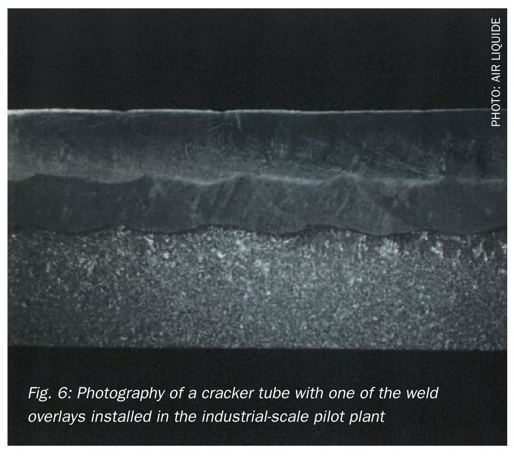
Fig. 5 shows a sketch of a tube tested in the industrial-scale NH3 cracking pilot plant. This tube has industrial dimensions (diameter, length, thickness) equivalent to the dimensions of future commercial plants. Its inner surface is covered with different protective coatings applied by weld overlay.

Fig. 6 shows a picture of the inner wall of this tube on which the reader can see the base alloy material and the protective coating.
Cracking tubes are not the only critical equipment in an ammonia cracker. Nitriding also poses a challenge for components such as piping and heat exchangers handling high-temperature ammonia gas. While increasing preheat temperatures improves energy efficiency and reduces specific ammonia consumption, it also intensifies nitriding.
In an ammonia gas atmosphere, the effects of nitriding on materials vary considerably depending on the alloy. In order to select the most resistant materials for each critical equipment according to its operating temperature, Air Liquide launched at an early stage tests of many alloy grades in its R&D material testing pilot at different temperatures and under pressure and gas atmosphere conditions equivalent to industrial operating conditions.
Fig. 7 shows the results of these tests on two different alloy grades that were exposed to the same atmosphere for an identical duration. The material in the left picture shows greater susceptibility to nitriding and spalling compared to the material in the right picture, which shows greater resistance.

Conclusion
Air Liquide is developing a new ammonia cracking technology for sustainable hydrogen production based on its vast experience with the steam methane reforming technology. The strategy involves a dedicated technology roadmap, extensive R&D programmes, and an industrial-scale pilot plant in Antwerp, Belgium. The pilot plant validates the technology at an industrial scale, calibrates design tools, and builds stakeholder confidence. Air Liquide’s data-driven approach, coupled with collaboration with key suppliers, ensures increased reliability, a deep process understanding, accurate feasibility assessments, and optimised performance and operating costs.
References