Sulphur 415 Nov-Dec 2024
30 November 2024
Sulphur degassing systems for large scale sulphur recovery units
SULPHUR DEGASSING
Sulphur degassing systems for large scale sulphur recovery units
Marcus Weber of Fluor discusses degassing units for large scale sulphur recovery units, evaluating the pros and cons of various available commercial technologies with the emphasis on mega size sulphur recovery units and focussing on how technology can lower degassing capex via economy of scale for new facilities or existing facilities undergoing expansion.Why is sulphur degassing necessary?
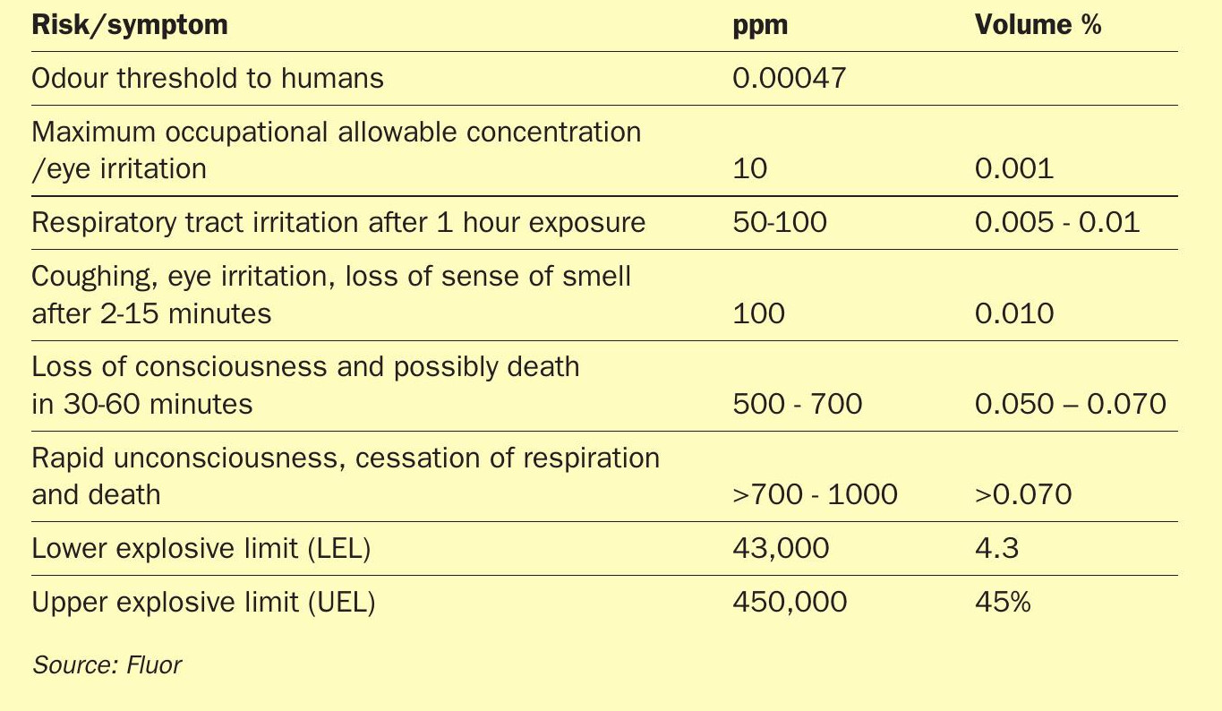
Sulphur produced in Claus sulphur recovery units (SRUs) typically contains dissolved hydrogen sulphide (H2S) and polysulphides (H2SX) in the rundown sulphur in the range of 200 to 600 ppm. This hydrogen sulphide when released from the liquid sulphur results in a concentration that can be toxic and if allowed to concentrate in closed spaces can increase to levels above the lower explosive limit and then also presents a flammability/explosive hazard.
Most regulatory bodies, transportation companies and end users require sulphur product specifications with 10 ppm or less H2S. Due to the toxicity and environmental hazards associated with H2S, sulphur is typically degassed within the SRU. If sulphur is not degassed within the SRU, it typically presents an H2S emissions concentration issue that requires additional sweep gas or other methods to control H2S emissions as it is transferred to downstream storage.
While not directly impacting sulphur degassing, most new SRU units are required to meet World Bank Standards of 150 mg/Nm3 SO2 emissions in the incinerator flue gas in addition to 99.99+% sulphur recovery efficiency (SRE). Sweep gas requirements for liquid sulphur storage pits/vessels/tankage can be rather large, further increasing capex/opex due to sweep gas recycle requirements and their impacts in designing recycle configurations in the SRU. Degassing sulphur directly in the SRU can minimise the amount of sweep gas required in downstream vessels and tankage as well as minimise potential for exposure to H2S as sulphur is transferred.
Chemistry of sulphur degassing
Claus SRU rundown sulphur typically contains 200 to 600 ppm H2S/H2Sx. Higher concentrations are typical in the first condenser, dropping to lower levels in the remaining condensers. Oxygen enrichment tends to increase the amount of dissolved H2S/H2Sx present in the rundown sulphur stream.
The chemistry and mass transfer steps involved with degassing are as follows:
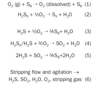
The first step in sulphur degassing is that the oxygen (reaction 1) must dissolve in the liquid sulphur. Air is most commonly used as the source of oxygen in sulphur degassing, however other streams containing oxygen can be used. The partial pressure of oxygen or the pressure at which the degassing is taking place can dramatically increase this mass transfer step. This stripping gas is typically dispersed as fine bubbles to increase the mass transfer as well as to agitate the sulphur.
Polysulphide decomposition (reaction 2) is slow and therefore is more directly in control of the residence time required.
Typical product requirements for degassed sulphur are 10 ppm H2 S or less and this, in combination with the bubbling agitation employed, results in excess oxygen being present. As a result of this, some generation of SO2 is also observed (reaction 4). With H2S and SO2 present, some Claus reaction (reaction 5) can also occur.
Once the above reactions have taken place, all of the gaseous products, must release from the liquid sulphur and are carried overhead with the balance of the stripping stream (reaction 6).
The interaction of sulphur viscosity and temperature must be addressed as part of the degassing process. Sulphur that hasn’t been degassed has dissolved H2 S which has a suppressing effect of higher viscosities, however, as the H2 S is stripped, this suppressing effect is removed. There tends to be an optimum temperature to both promote mass transfer and maintain sulphur viscosity for optimal degassing rates. It is not uncommon that Claus SRU rundown sulphur is cooled slightly prior to degassing to optimise the holdup time required to achieve the degassed sulphur product H2 S specifications.
Inlet sulphur composition must be accurately known to size the degassing system. The degassing process can be viewed as a half-life process, where with higher inlet H2 S/H2 SX concentrations, addition residence time to run through additional half-lives are required to achieve the desired outlet concentration:
Where:
N(t) = final H2 S quantity remaining
N(0) = initial H2 S quantity
t = time elapsed
t1/2 = degassing half life
This can be rationalised in the doubling of time required to degas to outlet concentrations of 40 ppm + one half life → 20 ppm + one half life → 10 ppm + one half life 5 ppm, and so on.
It should be noted that degassing does not necessarily eliminate requirements for sweeping of downstream vessels or tanks containing degassed sulphur, as H2 S can build up in confined overhead volumes, even with little dissolved H2 S. Storing degassed sulphur, however, does greatly simplify vessel air sweep requirements and often allows for natural convection as well as venting to atmosphere.
Degassing process historically
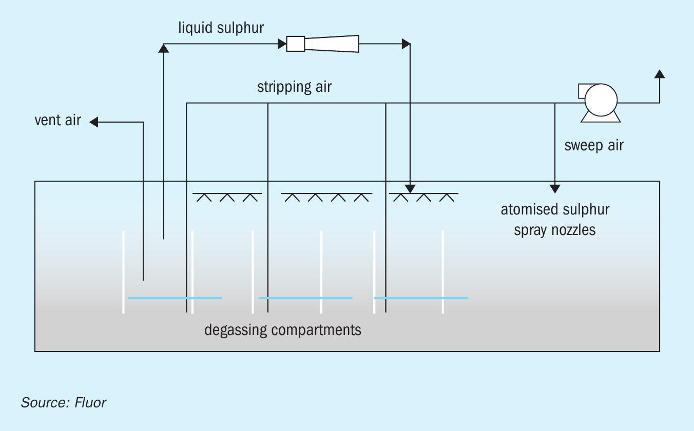
Historically, Claus SRU rundown sulphur has been collected in a below grade concrete sulphur pit, with internal steam coils for temperature maintenance and 1,000 air sweep to maintain the vapour space 100 at a comfortable margin 10 below the lower explosive limit of H2S. Sulphur degassing was located within the same pit, utilising air bubbled through the liquid sulphur pool for degassing. The degassing air stream combined with pit sweep air was routed to an incinerator via an eductor. In some cases, liquid sulphur was sprayed into the sulphur pit via a sulphur pump recycle to increase air contact and agitation. The working volume of these sulphur pits was typically set by the required degassing residence time, which was commonly in the 24 to 30 hour range.
This early in-pit degassing system resulted in a large sulphur volume/residence time and, as a result, a relatively large sulphur pit. Additionally, some segregation was required between the un-degassed and degassed sulphur sections of the pit. A large pit requires a correspondingly large pit sweep volume, which typically was sent to the incinerator, leading to increased SO2 emissions. Fig. 1 shows a traditional in-pit sulphur degassing process.
Sulphur pits by nature are below grade and covered to contain H2S off-gas. They are inhospitable places and not easily emptied for maintenance. The pits are of concrete construction and operate at elevated temperatures which leave themselves susceptible to corrosion from condensed water. Note that as they are below grade and operated at temperature, they experience thermal growth from initial construction, and therefore, from a cracking and corrosion standpoint, they are susceptible from both the inside (steam coil leaking) and outside (ground water). As the pit is difficult to empty, it frequently can collect debris from corrosion products and lead to subsequent pump problems.
When these SRUs go through a capacity increase, increasing the sulphur pit capacity is essentially impossible without significant capital expenditure. Often, the existing pit is utilised resulting in the pit residence time decreasing and as a result the existing in-pit degassing system is prone to underperformance.
Sulphur recovery units are changing
Sulphur recovery unit demands tend to change with time. For existing units, capacity increases are common and, with oxygen enrichment, capacity increases approaching 200% of original nameplate are common.
SRU SO2 emissions requirements tend to become more stringent over time. Even without an SRU capacity increase, the addition of a tail gas treating unit (TGTU) can increase the sulphur recovery as the sulphur that previously went to the incinerator is now recycled to the SRU and recovered as liquid sulphur.
Nowadays, new sulphur plants being built increasingly take advantage of economy of scale of the petrochemical facilities they serve. Gas plant SRU capacities are increasing both due to the growing size of the facility and because they are being designed for much sourer feeds. It is not uncommon that these large facilities are measured in multiple trains of greater than 1,000 t/d sulphur product. Product sulphur requirements are <10 ppmv H2 S in the sulphur product as well as requiring tighter SO2 emissions; these projects typically demand high sulphur recovery efficiencies which dictates that pit sweep and degassing unit vent streams are recycled to the SRU. Capex and opex are always at the forefront of decision making and the winning solutions are those with low lifecycle costs.
Modern degassing
Degassing providers are responding to the growing unit capacities, tightening project specifications, and optimised life cycle cost requirements. Owners are requiring systems that are less prone to corrosion, and easier to maintain.
Degassing licensors are or have developed processes that require shortened residence times which result in smaller equipment per unit throughput. Several licensors offer varying solutions:
- separate degassing vessel/out of pit degassing solution;
- degassing at pressure;
- solid catalyst;
- distributed catalyst.
The target of all of these degassing processes is to lower the overall lifecycle costs of operating the SRU. These degassing processes aim to decrease the residence time required to meet the residual H2S concentration remaining in the degassed sulphur product.
Degassing processes that are favoured tend to have additional benefits over and above just the degassed sulphur product. These solutions are used both in new grassroots SRU facilities, and also as retrofit solutions where exiting brownfield sites require increased capacity and are looking at innovative approaches rather than outright replacement with greater equipment sizing following the historical methodologies.
Reduced residence time to meet product sulphur requirements using an advanced degassing process allows existing equipment to process greater throughputs or, in a grassroots project, allows optimisation of the degassing process resulting in numerous benefits:
- Reduced cost of smaller equipment with equal or better process throughput capacity.
- Sulphur pits sizing is switched to that required for operation flexibility versus that of being bound to the traditionally 24-30 hours residence time because of the legacy degas process. Many operators are utilising 4 to 8 hour holdup capacity to address operational flexibility/equipment out of service, without having to be constrained with the traditional degassing residence time.
- Smaller equipment volumes require smaller pit sweep flowrates.
- Many operators are choosing to eliminate the sulphur pit completely with these reduced holdup volume requirements. Sulphur rundown storage is typically now favourably addressed via a vessel in a below grade vault. The vessel is below grade to allow for gravity drainage of rundown sulphur. The rundown vessel is externally steam traced/jacketed which greatly reduces the likelihood of a steam coil leaking directly into the process. The vessel is not exposed to a buried environment and as such ground water, corrosion and lack of ability to inspect are removed from the typical sulphur pit.
Simplification of implementation
What sets degassing processes apart is simplicity and cost effectiveness of their implementation. Sulphur degassing is not an isolated process; it requires integration into the SRU. It receives feed from the SRU and requires a destination for the degas H2S vent stream as well as the product degassed sulphur stream. This is even more important in large scale SRUs. Degassing processes that allow economy of scale further improve overall cost effectiveness.
As stated before, the reduction of residence time or holdup volume for the degassing process allows the sulphur rundown storage volume to be sized for a requirement other than degassing residence time. In retrofit solutions this may allow use of the existing pit with greatly higher sulphur production values. For new facilities this allows for a tighter plot plan and reduced construction quantities.
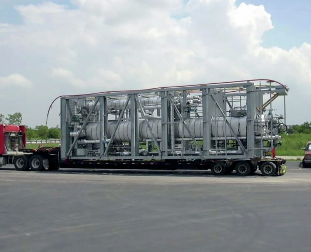
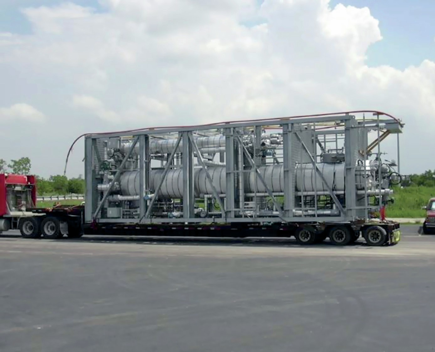
Out-of-pit degassing solutions allow for a purpose built degassing vessel which opens up several potential optimisations. An out-of-pit degassing solution can be unique to an individual SRU or common to multiple SRU trains. The existing or new much smaller forwarding pit(s) can route un-degassed sulphur to a common shared degas system. An out-of-pit solution can be modularised to allow cost effective construction and a quick turn-around for tie-ins to the overall facility.
A common degassing process servicing multiple SRU trains may allow simplification of the degassing H2S vent stream. This potentially avoids the need to duplicate the entire degassing H2S vent system in each SRU train. The degassing vessel can be co-located with the thermal reactor/ incinerator allowing for short vent piping. Less piping results in less utilities requirements to keep the vent heated, shorter lengths of piping minimise maintenance as there is less material to corrode or sections of piping to plug with sulphur.
Another simplification for degassing processes is to avoid duplication of degassed sulphur storage. From an economy of scale standpoint an offsite storage tank is much more cost effective with regard to cost of storage per volume of storage. The sulphur product eventually needs to get to the final storage location for loading to transportation, pipeline or forming of solid pellets. The fewer number of vessels between the final sulphur destination reduces the number of sweep gas streams and emissions points.
Technology pros and cons
Evaluation criteria are presented in this section to allow the user to determine the pros and cons of various technologies associated with their project. Project specific criteria or interfaces may simplify or complicate specific aspects of any technology and are addressed with respect to integration to the balance of the facility. Specific technologies are not discussed; however, several criteria are presented to facilitate selection.
Cost: Cost is usually one of the more significant criteria used in the technology evaluation. Cost should include both capital cost as well as the operating cost. This can be one of the more difficult criteria to evaluate as degassing technologies need to be integrated into the overall SRU. Evaluations to consider are how much equipment is required to implement? Are there changes to the existing SRU process that are required in order to integrate the technology? What utilities and in what quantity are required for the technology? If a technology uses a specific utility or piece of equipment that is at capacity in an existing facility, there is potentially a step change in cost required.
Experience base: What is the history of the technology? Does it have a wide experience list with hundreds of installations or is it just emerging with limited commercial implementations? Ask to see an experience list with project details similar to yours.
Degassed product spec requirements: What is the required product sulphur H2S residual? While the most common degassed sulphur specification is less than 10 ppm H2S residual, it is not the only requirement. If there is some flexibility in product specification, particularly in retrofit situations a specific technology may minimise the amount of work and cost required to implement.
Simplicity of operation/equipment complexity: How complex is the process? Does it use simple equipment and controls or are they complex? Simple processes use known equipment and controls, preferably existing equipment/controls for a retrofit installation. As an example, are additional pumps required for the process; can it use existing pumps or are no pumps required if the pressure profile allows available pressure to be utilised.
Integration into the overall SRU process: The actual degassing process needs to be understood, but also the impact to the SRU for the feeds/utilities to the degassing process as well as the product sulphur and overhead vent stream. Controls permissives and interlocks impacting the overall integration should be evaluated as well; Does the degassing technology simplify or complicate the operation of the associated SRU?
Consumables/catalysts: Does the process require catalysts and if so are they continuously added? How long does the catalyst last and what is performance as catalyst degrades? Is there operational experience with this at other similar sites? Contrast this to a process that exploits simple operating parameters such as temperature and pressure which are easily manipulated and understood by operations.
Lessons learned: Does the technology supplier have any lessons learned of the process? What were the solutions implemented? Are the lessons learned one-off or perhaps individual site mis-operation. Does the technology supplier readily share the lessons learned to avoid repeat at your site?
Ease of retrofit if implemented to existing SRU: How complicated is the integration of the technology to the existing plant? Does it require extended shutdowns to interconnect? For example, are the interconnections simple piping connections or do they require shutdown and work inside the sulphur pit? Consider the feeds, vent streams, product streams as well as any utilities. What is simple in one facility may be very complicated in another facility.
D’GAASS process implementation in a large scale SRU facility
This section reviews the Fluor/GAA D’GAASS process specifics and highlights scale of economy benefits with installation in large SRUs.
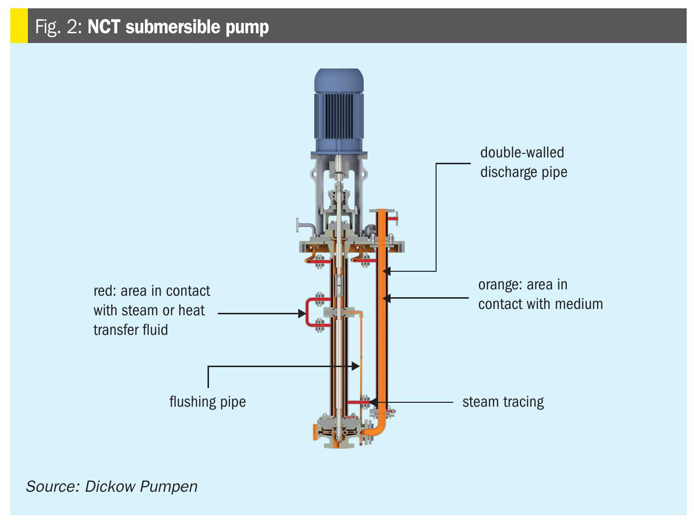
There are currently more than 140 D’GAASS units operating around the globe with utmost reliability and availability/onstream time. Individual installations range in size from 10 t/d to sites with multiple units as large as 2,500 t/d capacity each. Installations typically include a D’GAASS unit per SRU train, however, frequently a single common D’GAASS unit serves multiple SRUs. The D’GAASS process consistently achieves less than 10 ppmv residual H2S in the degassed sulphur. A typical D’GAASS process flow diagram is shown in Fig. 2.
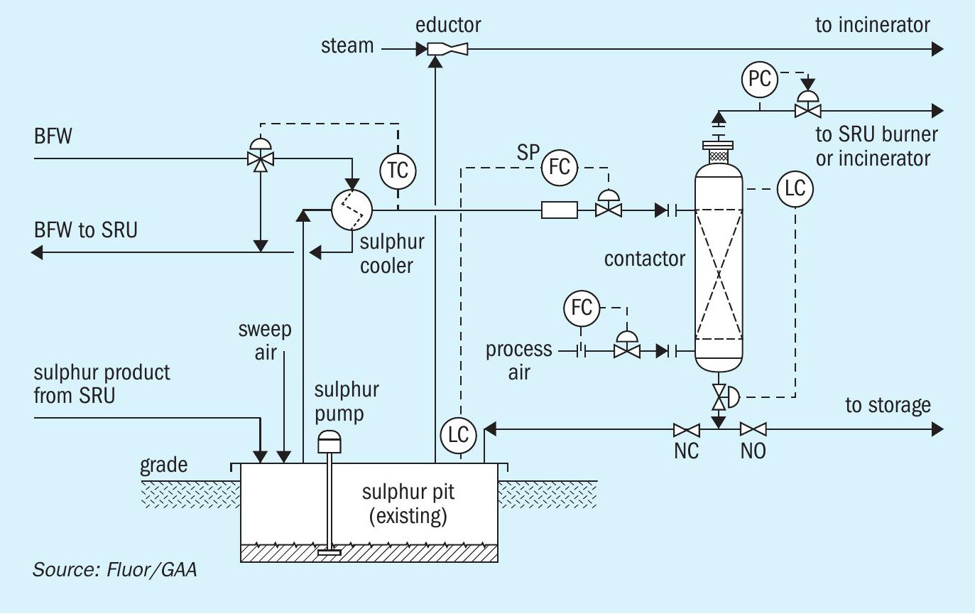
The D’GAASS process countercurrently contacts liquid sulphur with dry process air at pressure. Higher pressure operation significantly accelerates sulphur degassing as the partial pressure of oxygen is higher and therefore promotes the decomposition of polysulphides as well as H2S. Air is introduced at the bottom of a vertical column and is distributed across the column where it contacts un-degassed sulphur introduced at the top of the vertical vessel. As the air bubbles rise in the contactor, they promote both the degassing reactions as well as stripping the H2S into an overhead vent stream. For optimal degassing, un-degassed sulphur is cooled to 135°C prior to entering the vertical contactor column. Sulphur residence time in the contactor is approximately 1 hour and 10 ppmv residual H2S or less is guaranteed.
Integration into both existing SRUs and new SRUs is greatly simplified due to the pressurised contactor operation. Both the overhead vent stream and the degassed liquid sulphur stream are at pressure. Contactor overhead vent gas can therefore be pushed to the SRU thermal reactor by pressure differential via simple control valves. Similarly, the degassed liquid sulphur product can be pressured to degassed sulphur storage without the use of pumps.
Feed from the SRU sulphur rundown pit is usually pumped. Typically, existing sulphur pit pumps have sufficient pressure for direct use by the D’GAASS process and can be used without modification. Because the sulphur degassing occurs in the out of pit contactor, there is no longer a 24-30 hour residence time requirement for the sulphur pit as for traditional sulphur degassing processes (see Fig. 1). As a result of this, the sulphur pit storage volume is independent of the degassing residence time requirement. Many of Fluor’s clients in new installations prefer a sulphur storage vessel configured in a concrete vault in lieu of the traditional, maintenance intensive concrete pit. In this configuration, a small horizontal vessel, with external heat tracing or jacketing, is in a much more maintenance friendly configuration which eliminates internal steam coils and the potential for corrosion from water (both internally and externally to the vessel).
The vertical configuration of the contactor vessel allows for very efficient use of the stripping air as it is completely countercurrent to the sulphur stream. Horizontal vessels typically use multiple packing columns and require multiples of stripping air to feed each individual packing column. This additional stripping air increases the size of the reaction furnace and incinerator as well as increasing the utilities requirement for horizontal configuration arrangements.
The D’GAASS contactor effectively eliminates corrosion utilising a jacketed vessel. The overhead vent stream which contains H2S, O2 , H2O, SO2 as well as other inerts present in the process air stripping stream equipment and piping needs to be maintained hot to avoid wet/ sulphurous acid corrosion. The contactor vapour space and overhead vent lines are jacketed with slightly higher pressure steam to keep water in the vapour phase. Experience has shown this to be a very effective method of minimising corrosion.
The sulphur cooler can utilise a variety of cooling streams. Use of boiler feed water allows the cooling sulphur to preheat boiler feedwater which improves overall energy efficiency of the SRU. An alternative, such as a steam reboiler with a separate waste steam condenser, allows the sulphur to be cooled to the optimum temperature without the complication of heat integration of other streams.
The D’GAASS process is very cost effective with increasing sulphur degassing capacity. Increased capacity is accommodated by increased contactor diameter while maintaining the overall contactor height. Again, typical contactor residence time requirement is approximately one hour; the volume of the contactor increases as the square of the diameter. Similar economy of scale benefits result from the efficient vertical orientation of the contactor vessel and the counter current air stripping stream flow configuration.
Alternative stripping streams can be used if spiked with oxygen. This alternative allows the D’GAASS process to be used in a CO2 capture configuration where air is substituted with a CO2 /O2 mixture, again at pressure. Recycling of this CO2 / O2 degas overhead stream to the reaction furnace prevents nitrogen introduction into the thermal reactor tail gas when 100% oxygen enrichment is utilised.