Sulphur 403 Nov-Dec 2022
30 November 2022
Commissioning amine plants in extreme environments
PLANT COMMISSIONING
Commissioning amine plants in extreme environments
Operating plants in extreme environments can present unique challenges. If these challenges are not anticipated and addressed in design and commissioning, the plant will not be able to start up nor meet its specification. This article examines the challenges faced in commissioning amine plants operating in three diverse environments (extreme heat, extreme cold, and offshore) and the technical and procedural solutions employed to resolve them. Mike Sheilan, Ben Spooner, Kaiyr Tekebayev, and Philip le Grange, Amine Experts.
The challenges and their technical solutions in the commissioning of seven amine units in very challenging environmental conditions are described in this article. The amine units operate in extreme conditions of ambient heat and cold and in locations with restricted access (i.e., offshore).
Environmental hazards for staff (hypothermia, dehydration, swaying platforms, etc.) make mechanical work both more dangerous and more difficult. Logistically, some of these locations can be hard to reach, rendering the replacement of chemicals or delivery of unanticipated piping/equipment difficult. As a result, corrections for design and commissioning errors can be very expensive and may delay plant start-up significantly.
It is the authors’ hope that learnings from these stories will help our industry improve its commissioning practices in demanding environments.
Case 1: Extreme ambient hot and unusual inlet gas contaminants
An amine unit start-up can be a daunting experience at the best of times, but during the Middle East summer, when ambient temperatures can reach or exceed 50°C, the difficulty level increases dramatically. And when that start-up includes an owner who has never dealt with sour gas before, and then having to operate a plant designed and built by a firm that has never built one before, the pressure is even greater. It becomes hard to differentiate between the sweat caused by the heat and the sweat caused by the stress to force a new plant to operate to its design specification.
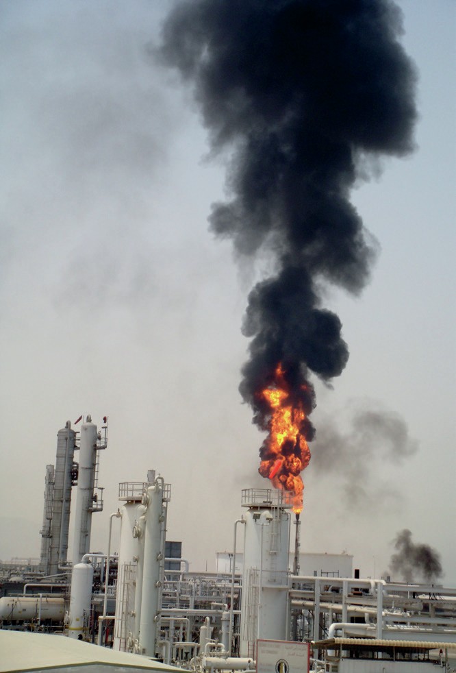
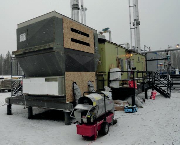
Amine Experts’ involvement began after an initial failed start-up, resulting in a plant with plugged vessels, sour treated gas, and the flaring of large quantities of unprocessed sour gas (Fig. 1).
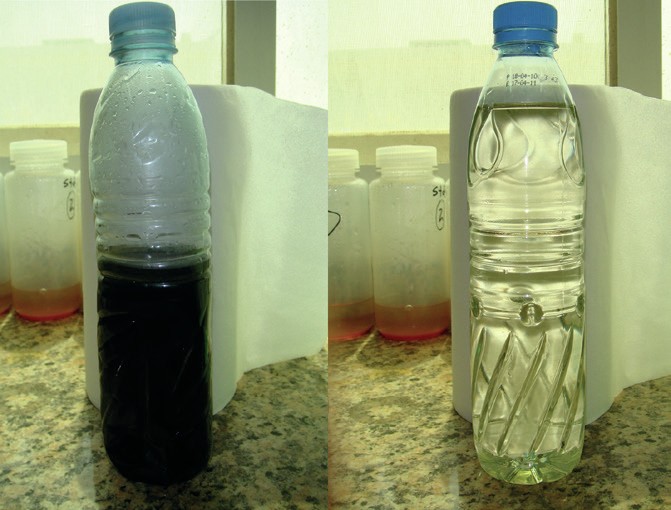
In the original start-up attempt, the plant was unable to process gas after just a few days of operation due to plugging in the contactor and flash drum. The treated gas did not achieve the required H2 S specification, so it did not meet contractual obligations for sale. The amine solvent was black and viscous and did not circulate well through the system.
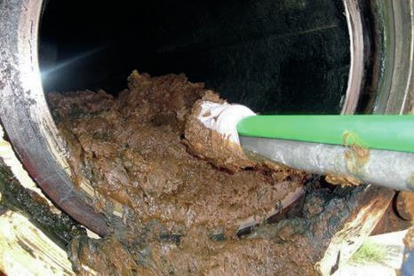
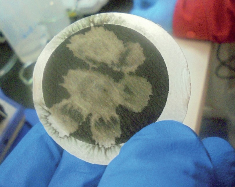
Analysis of contaminants entering the amine unit revealed a mixture of solids (primarily iron sulphides) and heavy hydrocarbons, including asphaltenes and waxes (Fig. 2).
The heavier hydrocarbons which were the basis of the fouling material came from operating the lean amine much cooler than the hydrocarbon dewpoint in the gas such that the mixture moved into the two-phase region. Ideally, the feed gas temperature would be increased to stay above the hydrocarbon dewpoint, but this would require warmer amine as well, and then the contactor would not meet treated gas specification.
Improper inlet separation technology
The plant had been designed with a large vertical inlet gas separator and a filtercoalescer, with the intent that liquid and solids would be separated in the bulk vessel, and aerosol mists that happened to carry-over would be captured by the coalescer.
A review of the engineering drawings revealed that the inlet separator lacked a demister pad and the coalescer was installed incorrectly. Furthermore, the feed into the coalescer was connected to the outlet piping of the vessel (the upper chamber with the elements). Because of the insufficient residence time caused by the loss of volume occupied by the elements, the fluid level in the upper chamber rapidly exceeded the HHL (highhigh level), flooding most of the chamber, and rendering the elements ineffective for coalescing as they were submerged. The separator/coalescer thus offered almost zero protection for the amine system.
Technology options for preventing fouling
The two options considered for correcting the feed gas conditioning problem were:
- A gas chiller followed by a second separator upstream of the original inlet separator and coalescer (design company)
- Retrofitting the current coalescer into a particle filter and installing a properly oriented coalescer downstream of the existing coalescer (Amine Experts)
The design and construction company suggested the chiller option, and even installed a unit ‘free of charge’ to the owner because they were confident that it was the solution. Amine Experts took issue with the chiller approach since it was felt that the tubes in the chiller would quickly plug with solids. Although the chiller was installed on a pad at the plant site, it was never connected and eventually dismantled. Instead, Amine Experts was contracted to design and construct the new coalescing device, which the client installed downstream of the existing coalescer. In turn, the existing coalescer was redesigned into a particle filter to protect the coalescing elements in the new vessel from solids. Ultimately, this combination proved to be the ideal fix, as the plant has run uninterrupted for over ten years, removing between 1-3 m3 / day of liquids from the feed gas, while not experiencing any fouling of the amine contactor.
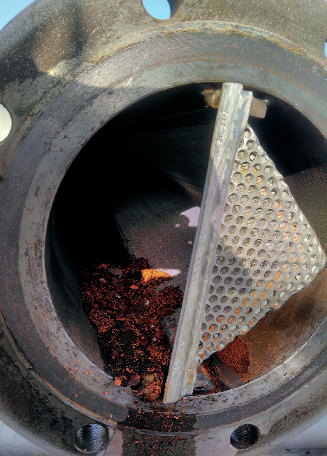
Flash drum fouling
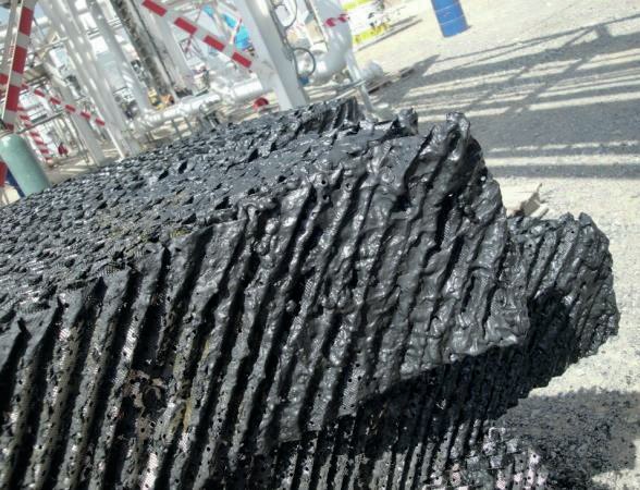
The original flash drum was too small for the design amine circulation rate. It provided a residence time of less than three minutes, much less than the recommended 25 minutes. Recognising the limitation, the designer tried to artificially improve the separation time by installing coalescer pads (which was simply structured packing) inside the vessel.
Rather than improving separation efficiency, the coalescing pads instead plugged off with heavy hydrocarbons and iron sulphide, which had entered with the feed gas due to the poor inlet separation, reducing the already short residence time to less than a minute. It is not good practice to install any device in a flash drum that is prone to fouling, as the inherently “dirty” nature of amine systems (especially on the rich side) will cause the device to plug rather than coalesce. The result in this plant is shown in Fig. 3. The owner decided to remove the offending coalescing pads and add a rich-side filter downstream of the flash drum to protect the lean/rich plate and frame exchangers. So far, that decision has proven to be a sound one as the lean/rich exchangers have remained clean.
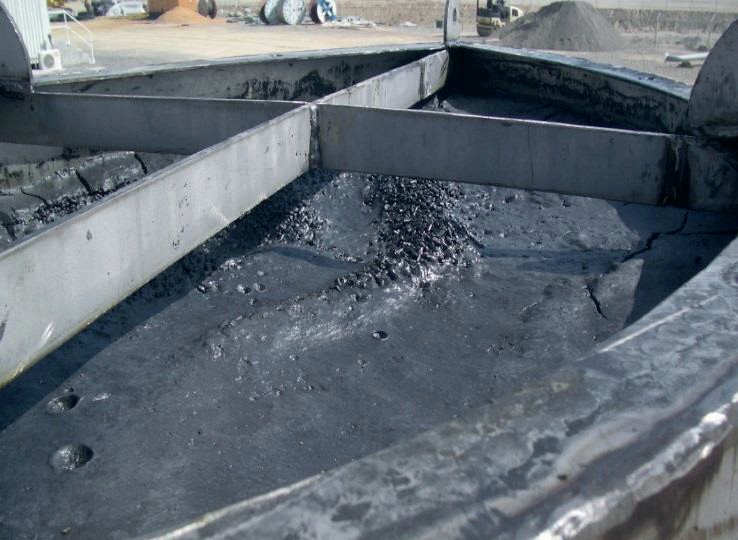
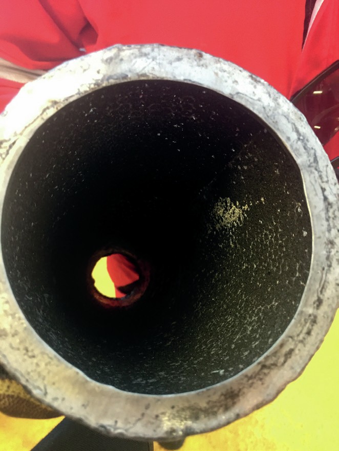
Activated carbon bed fouling
As there was no lean amine pre-filter upstream of the carbon bed in either the original design or the as-built plant configuration, the flaw was obvious. This was an unfortunate decision, as carbon beds will act as impingement filters, and will easily plug with solids circulating in the lean solution, as shown in Fig. 4. The fouled pores then prevent the activated carbon from doing its job of removing foam-promoting contaminants in the amine. As such, foaming was a regular occurrence during the initial start-up. A pre-filter should have been installed.
System preparation
Due to the fouling experienced in the first start-up attempt, a thorough cleaning of the system was necessary before re-starting. Units with packed columns require an extremely clean circulating solvent or they will plug rapidly.
Amine Experts’ strategy for cleaning included:
- In sequence:
– Cold-water flush
– Hot-water flush
– Cool 3% amine flush
– Hot 3% amine flush
- Selecting sample points for checking fluid condition and appearance.
- Setting up Millipore filters in certain locations on the lean and rich loops to ensure cleanliness.
- Instituting analytical protocols to check fluid quality and for enabling the decision to begin the next stage of cleaning.
- Setting up the flush fluid burn pit (this is not a standard feature on amine plants, so in most cases, provision for waste fluid disposal is necessary).
The initial cold-water flush was repeated twice to remove large solids from the system. The warm flush loosened more contaminants.
After the water flushes, a 3 wt-% amine solution was circulated since it has better detergent properties than water and prepares the system for the alkaline environment that will exist during operation. Soda ash can also be used instead of amine.
After several flushes the solution improved from a dark black to clear and pale straw colour with no indication of any solids or secondary layers (Fig. 5), as hoped. With water being a rare commodity in a desert environment, the relatively clean final flush fluid was used as make-up water and the system then charged to the correct full 50 wt-% strength.
Once the system was clean, the inlet coalescers and filters were correctly installed, and the rich filtration system was in place, feed gas was introduced to the system on the expected date. As opposed to the initial start-up that failed after only a few days, the plant was operational for seven years before a turnaround was scheduled.
It is difficult to convey how uncomfortably hot it was for the entire project. Frequent breaks are essential despite the hectic schedule. Nerves are frayed. People suffer from lack of sleep and are easily frustrated. Persistent professionalism was required by all parties to get this plant successfully up and running.
Case 2: Extreme ambient heat
The ability of a lean amine solution to sweeten a feed gas stream is affected by the temperatures in the amine contactor. A warmer amine has less overall absorptive capacity than a cooler amine, so designs should always incorporate an environment-appropriate cooling system for the lean amine. For most plants around the world, forced-air coolers are the preferred equipment because apart from a few days per year, the ambient air is cool enough to achieve the necessary heat exchange on the hot lean amine. The requirement is that it must be 5-7°C warmer than the feed gas temperature. But in extreme heat environments, (45 to 55°C), aerial coolers will not be able to meet the process cooling requirements, so supplemental trim coolers, using water or propane, are specified in the designs.
An amine system in a hot Middle Eastern desert environment was started up with an aerial cooler followed by a propane chiller. It was working well to control the temperature in the absorber (which in the case of an MDEA-system optimised H2 S removal but also maximised CO2 slip). A cooler amine absorbs less CO2 , which was critical to the performance of the sulphur recovery unit (SRU) which needed an acid gas feed with as little CO2 and as much H2 S as possible.
A problem with the propane compressor was going to force a shutdown for repairs lasting several hours which would put the temperature of the lean amine at the mercy of the aerial coolers, a worrying proposition with an ambient temperature of 50°C. A decision was made by the operating company to chill the lean amine as much as possible while the propane compressor was still running to minimise the effect of its absence during the repair. The assumption was that by starting with a cold amine, the inevitable heating effect on the solvent could be delayed until all the inventory had made its way to the regenerator and then back to the absorber before there was an undesirable impact on the treated gas. Unfortunately, almost immediately, the absorber showed signs of foaming with an elevated differential pressure (dP). Before antifoam could be added to the unit, the absorber dP rose so dramatically that a large quantity of amine carried over from the absorber into the downstream dehydration system.
Amine Experts was asked to troubleshoot the foaming episode and it was clear that the foaming was caused by rapid condensation of a large volume of heavy-end hydrocarbons that raised the foaming tendency of the amine. The condensation was a direct result of the overzealous cooling of the lean amine to 15°C less than the feed gas temperature. A better option for preparing for the propane compressor shutdown may have been to complete the repairs at night when ambient temperatures were more amenable or recognising that the minimum target for the lean amine should never be colder than the hydrocarbon dewpoint. The plant should have also been better prepared to cut back the feed rate and dose the system with antifoam before the easily avoidable loss of a good portion of the system inventory.
Case 3: Extreme ambient heat
During a summer start-up of a large LNG facility, the hot ambient temperatures resulted in the lean amine feeding the absorber being warmer than expected. Although the treated gas CO2 content increased it was still meeting specification. This was a concern to Operations and the problem was diagnosed as too much amine flow rate through the coolers, resulting in inefficient heat transfer. The circulation rate was subsequently decreased, reducing the lean amine temperature. Perplexingly, the CO2 concentration in the treated gas continued to increase, eventually going off-specification.
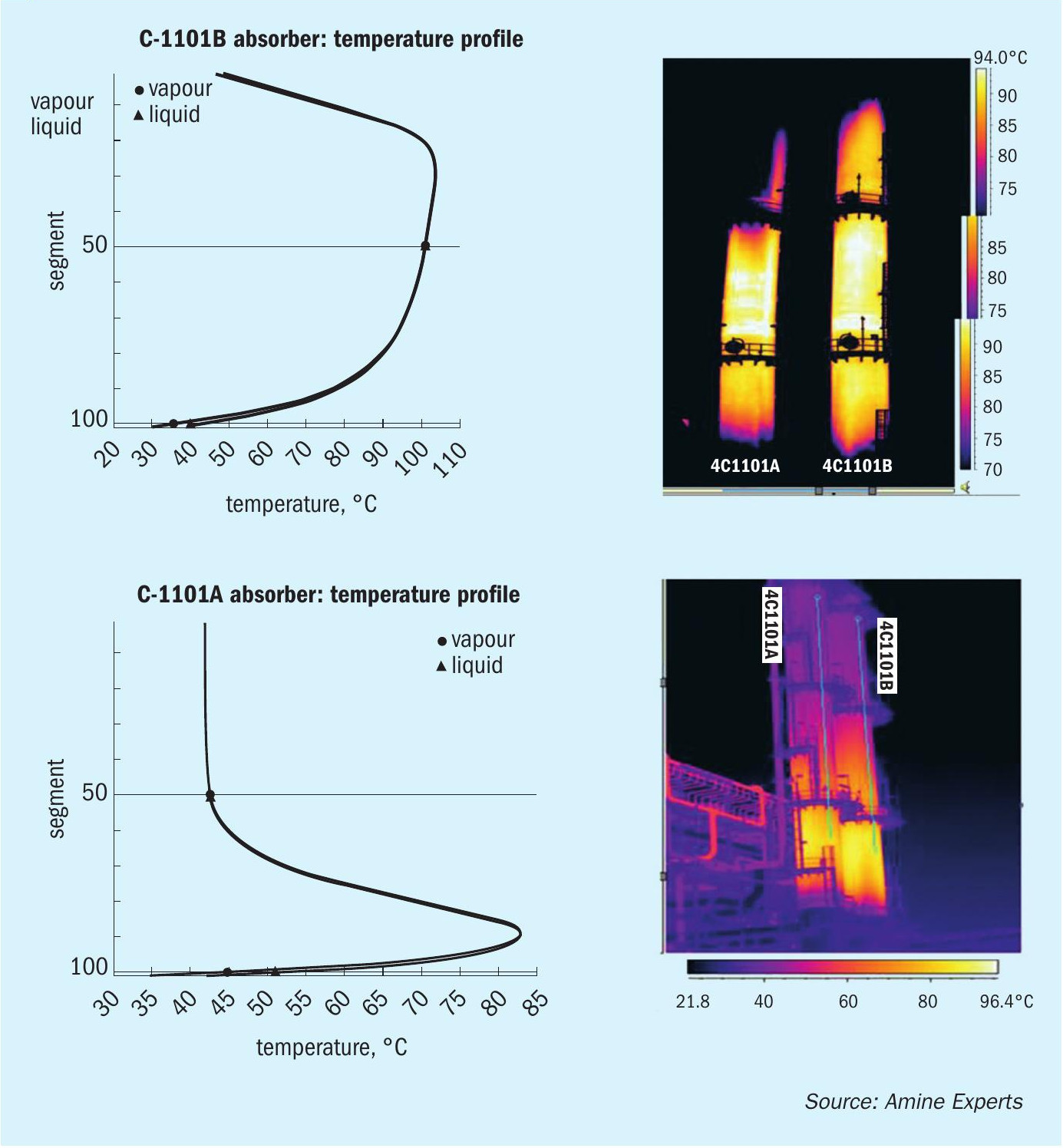
Amine Experts was contacted for troubleshooting support. A simulation of the system determined that the problem was an excessively high temperature bulge inside the absorber caused by the decrease of lean amine flow. Even though the new flowrate produced cooler amine, it was countered by the lack of “quenching” amine which allowed the exothermic temperature bulge to increase to an excessive degree. Unless there are thermal indicators on the tower, it is difficult to know what the temperature profile of an absorber looks like. Simulations showed much of the column exceeded 95°C (Fig. 6), which is so hot there is no absorption between amine and CO2 and as a result the CO2 content of the treated gas increased. The treated gas temperature also increased so dramatically that the downstream liquefaction plant had to cut back almost 40% on throughput because there was insufficient cooling capacity for this hot feed gas.
Amine Experts modelled the system and determined the optimum circulation rates, steam rates, and system temperatures to meet the required treated gas CO2 specification and keep the treated gas cool enough to run at full capacity downstream in the liquefaction trains. The resultant absorber temperature profile (Fig. 6) lowered the bulge temperature to a manageable value and resulted in a much cooler treated gas. Optimisation of amine unit parameters not only improved the performance of the amine system, but also permitted full gas production through the liquefaction trains.
Case 4: Extreme ambient cold
A 27-year-old skid package that had spent several years mothballed in a boneyard was re-purposed and relocated to sweeten fuel gas in a remote northern location, where temperatures can be as low as -40°C. Final plant construction and commissioning was scheduled for midwinter as it was not possible to transport equipment by road during summer when the ice-roads turned to marsh.
System preparation
A site inspection of the vessels showed that when they had been mothballed they were filled with glycol to prevent them freezing. However, the glycol appeared to have been contaminated with fine silt. Silt is a potential fouling- and foam-promoting material. There were still appreciable amounts of this material in the unit and most of the drain connections were plugged (Fig. 7).
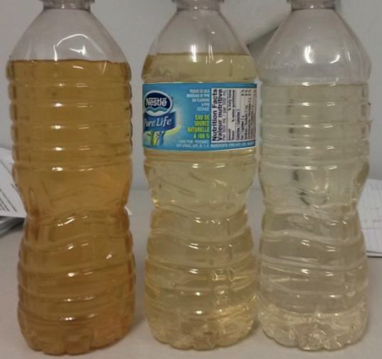
An aggressive program of unit cleaning was clearly needed. As a first step, the units were washed with high-pressure water lances while mechanical work was proceeding. With conventional techniques, the time needed to clean this system to an acceptable level would delay the start-up of the plant and other dependent units. A quicker cleaning program was developed in which the various rinse steps (see Case 1) were performed and the dirty cleaning solution was continually removed from several low points in the system and made up with fresh cleaning solution. While this generated considerably more waste, it proved time-effective (Fig. 8). In contrast to commissioning an amine plant in a desert environment, water was readily available.
Although the plant was located inside a heated building, the heating system depended on gas produced from the facility, which was not yet producing. Electric heating was used instead, with power supplied by portable generators, but they had difficulty keeping up with the demand and multiple power failures meant a constant battle against frozen lines as the washes began.
Methanol was added to the liquid-filled drain lines outside the plant enclosure to prevent them from freezing. Regardless, a section of reflux piping outside the building was not self-draining and froze despite insulation. Thawing it caused some delay because it could only be reached by crane.
Installation and equipment errors
A section of the aerial cooler that provides cooling for the lean amine and condenses the amine regenerator overhead gases did not arrive with the old plant package and its absence was not noted until commissioning began. This section, which recirculates warm air inside the exchanger, prevents overcooling the amine (which would have made it too viscous to pump) and freezing of cooler and condenser tubes. Waiting for fabrication and delivery of this missing piece would have delayed start-up by up to two weeks. This was deemed unacceptable, and some creative engineering resulted in a temporary solution that permitted start-up of the plant (Fig. 9).
The reflux pumps were wired incorrectly causing them to rotate in reverse and caused another short delay to the initial start-up. A much longer delay was caused by the lack of high-point purges on the hot-oil system (supplying the heating medium to the reboiler). Water contaminated the hot oil during its initial loading and boiling it out of the lines took considerable time because of insufficient vents in the hot oil circuit.
Post-weld heat treatment was done on all welds connecting the amine plant to its new service at Amine Experts’ insistence. This prevents potential corrosive failures due to hydrogen-induced cracking (HIC) which has caused fatalities on amine plants in the past. It also reduces the hardness and the chances of brittle fractures.
Legacy issues
There can be a significant reduction in project capital expenditure (capex) if a suitable existing mothballed plant can be re-purposed as opposed to design and fabrication of a new plant. That said, there were several minor issues worth noting:
- Flash tank internal geometry was unclear; no drawings were available, and the borescope camera was unable to get a good view of the internals; a gamma scan was needed for clarity.
- Several redundant pipes were left over from the previous service. These should have been removed from drawings and not re-installed.
- Obtaining replacements for defective 1980s control instrumentation proved challenging.
- The heat-medium control scheme was not optimal and could have been re-worked to perform better. Being an old plant doesn’t mean the control philosophy should be outdated.
- The process flow rates in the “new” system were less than the design of the original plant, resulting in pump impellers that were larger than necessary; appropriately sized impellers will make the plant easier to control and be more energy efficient.
After one false start because of some flange leaks (H2 S-detection equipment is critical in the start-up of a sour amine unit), the unit was successfully brought online before the project deadline and has been operating for years without any major process upsets.
Case 5: Mobile offshore facility
A floating production storage and offloading (FPSO) unit operating offshore in Asia was designed to treat up to 100 million std. ft3 /d of gas to a specification of <16 ppmv H2 S and <3.5 mol-% CO2 . As is typical in offshore applications where space is at a premium, both the absorber and regenerator internals contained structured packing. Furthermore, getting equipment, tools, chemicals etc., are far more difficult on an FPSO unit compared to a land-based plant so when things don’t work as planned, creative and outside-the-box thinking is often necessary to achieve success.
On commissioning, the FPSO unit tried for several days to meet the design H2 S specification. It was unsuccessful, with the H2 S concentration in the treated gas rapidly reaching as much as 300 ppmv. The longer the plant was in service, the greater the H2 S became, which coincided with a steady, gradual rise in the amine lean loading.
The parameters observed in the regenerator led operators to believe there was a flow distribution problem which allowed steam to channel through the structured packed interior and not contact (regenerate) the amine. The system was shut down, drained, and the regenerator inspected. Amine Experts was contracted to perform the inspection, then stay aboard to ensure successful start-up of the system.
A thorough mechanical inspection was conducted by Amine Experts and the hardware was generally in good condition and fit for purpose. Attention was therefore turned to the process itself.
Simulations out to sea
The initial start-up of this system relied heavily on operating parameters determined by simulations; however, simulations assume proper contact between vapour and liquid inside the absorber and regenerator. This of course is NOT the case if the liquid and vapour conditions are not right. It is important, then, that in the regenerator a certain minimum amount of steam always be generated such that contact with the amine can be guaranteed.
New, updated operating conditions were established for the regenerator, and to verify the conditions were correct, a temperature indicator on the pipe feeding lean amine to the reboiler was removed and replaced with a sample point (which had a cooling coil). This allowed the H2 S concentration in the amine feeding the reboiler to be measured. The H2 S content of the lean amine leaving the reboiler (which Operators sample on a regular basis) should be very similar. Measuring the H2 S in the amine feeding the reboiler is the best way of determining the effectiveness of the regenerator distributor and packing. Ideally, very little H2 S should be regenerated from the amine in the reboiler itself.
Amine Experts determined the minimum flows of liquid and vapour to ensure proper contact between steam and amine in the regenerator. A 20% safety margin was added to each value and the operators were instructed to hold these targets. The steam flow to the reboiler was set at a ratio of 120 kg of steam per m3 of amine circulation rate, which is more than the industry average of 100-110 kg/ m3 . Structured packing requires adequate vapour traffic to ensure proper contact and distribution of the liquid. Since none of the operators had experience using structured packing before arriving on the FPSO, this was a primary contributor to the failure of the original start-up – it was being operated like a traditional trayed regenerator.
Once operation had stabilised under the new operating targets, the treated gas was analysed repeatedly, with the H2 S concentration measured at as little as 0.2 ppmv and as much as 3.5 ppmv. The variance in H2 S was clearly related to the steam flow rate to the reboiler. When the H2 S was at its minimum, the steam-toamine ratio was at the ideal target of 120 kg/m3 determined for this system. This ratio was the most important operating element to meeting the H2 S specification in this plant.
The sample point of amine feeding the reboiler proved useful in verifying that the operating parameters in the regenerator were set correctly. The reboiler inlet sample contained 700 ppmw H2 S while the outlet sample had 600 ppmw H2 S. The bulk of the regeneration of the amine was, therefore, correctly being done in the tower.
Staying on-line
While calculations and simulation outputs are useful in providing guidelines and targets for the operators to follow during start-up, the reality of bringing an amine plant on-line is that many operating parameters are initially very difficult to achieve. Although the H2 S remained on spec in the treated gas while Amine Experts-supervised the start-up, there were numerous obstacles:
- Maintaining a constant utility steam pressure proved to be a challenge; the target was for the steam to be 3-4 barg, which is at 145-151°C when saturated. Many times, the steam pressure dropped to as little as 2.5 barg, which is 139°C.
- The lean/rich exchanger worked better than predicted, delivering a regenerator overhead temperature of 115-120°C, as opposed to the expected 105°C. This increased the water content of the reflux system and triggered the reflux accumulator high-level alarm.
- The reflux temperature of 45°C could not be held constant, and the temperature was often 35°C or less. This, combined with the well-heated rich amine feeding the regenerator, overwhelmed the reflux system and there were frequent high-level alarms in the reflux accumulator. Reflux water had to be manually drained to the sump tank.
- The flash tank target pressure of 4 barg could not be maintained once gas rates were increased. At high rates, and with the pressure control valve wide open, the lowest pressure attained in the tank was 6.8 barg. On investigation, an incorrectly sized orifice plate was discovered which was holding pressure on the flash gas line. The orifice was replaced with one of the proper size (luckily there was one on board), and the flash pressure returned to design.
- The inlet gas temperature to the absorber was difficult to control. The target was 35°C, but most of the time it was 25°C. The concern was that this would overwhelm the inlet coalescing filter, but this did not happen, and there were no foaming problems. Fortunately, unlike the hot environment start-up, this gas was nowhere near its dewpoint.
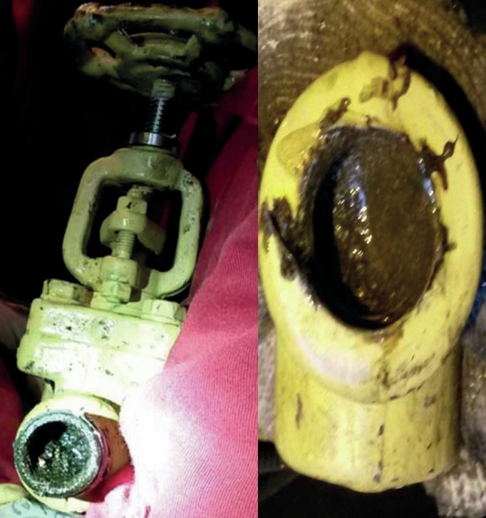
- The suction strainers (Fig. 10) plugged frequently, and were eventually removed, because of a high solids content in the amine.
The situation was exacerbated by the lack of operator training for the systems and equipment with which they were working. For example, single-use filter and coalescer cartridges were removed, rinsed, and re-used, resulting in amine that was heavily contaminated with solids and hydrocarbons. The solids were later identified as likely being iron, based on their reactiveness with acid (Fig. 11). This could have quickly led to fouling and foaming if a temporary remedy (circulating amine through the sump tank, which has a filter) had not been found.
Being offshore brings its own set of challenges:
- Inventories of disposable items can be low, and re-stocking filters was a long process. This encouraged operators to unwisely re-use their spent cartridges. And, if flanges are opened, the gaskets must be replaced with new ones. Make sure they are in stock before opening flanges or disconnecting equipment.
- Because the filters are hard to obtain the amine must be kept very clean. Minimise hydrocarbon contamination and corrosion at all costs.
- FPSO units are constantly moving, and this can cause amine to splash around inside vessels. This affects performance of the flash tanks, and eliminates the option of using trayed absorbers or regenerators.
- The hydraulics of structured-packed towers are quite different from those of trays. It’s important to be aware of the differences and learn to not always rely on simulators to make accurate predictions.
- Safety is far more serious offshore due to the difficulties in evacuating an injured person. Only enter the plant when necessary, and always have all required PPE.
- Chemicals such as amine, antifoam, and laboratory titration solutions are difficult to acquire, so care must be taken to not waste them.
- Extreme weather and saltwater causes equipment to corrode quickly. Be prepared to expend a lot of energy opening equipment that has been sealed for several months.
- The surrounding oceanic environment is very ecologically sensitive, and the oil and gas industry are held to very high standards when it comes to pollution. No chemicals can be spilled into the water.
Case 6: Offshore gas
An offshore facility in the North Sea was designed with an exotic, expensive solvent to handle a feed gas that was predicted to contain close to 1 mol-% H2 S and 1,000 ppmv mercaptan. At start-up, the gas was found to contain less than 10 ppmv H2 S and no mercaptan, so the expensive amine system was only required to remove about 5 ppm of H2 S to meet the specification. This was an expensive mistake. With the correct feed gas composition, the amine solvent choice would likely have been different, or an alternate technology selected.
Like the hot environment case study in this paper, soon after the initial plant start up, the filters plugged with debris from an improperly cleaned system. In attempting to replace the filters, it was determined that the filters were only isolated by a single valve, rather than the mandated double block and bleed (double isolation) valves required for offshore systems. Because the filters could not be safely replaced, the amine system could not function properly, as there was no way to prevent the packed internals of the contactor and regenerator from plugging. Fortunately, the original design included a solid adsorbent bed for final H2 S and mercaptan removal if any passed through the contactor. The amine system was thus bypassed, with the feed gas flowing first through the adsorbent bed for H2 S removal, then to dehydration and on to sales. Without the adsorbent bed, the product gas would not have successfully met the pipeline requirements for H2 S content, although the adsorbent performance must be monitored constantly as it will need replacement before it is spent.
On review, Amine Experts identified:
- A failure to accurately analyse and predict feed composition led to large unnecessary expenditures on the plant design, construction, and solvent choice.
- Due to a failure to properly train staff on H2 S safety, the operators were unreasonably in fear of minute concentrations of H2 S.
- Improper hydraulic testing of the unit with salt water led to aggressive chloride corrosion in the amine unit.
- Improper construction of isolation valving for the filtration system prevented routine maintenance.
Case 7: Offshore gas
A sweetening platform offshore was designed to process a sour feed gas to less than 2 ppmv H2 S and 2% CO2 in the treated gas. Shortly before the plant started up, however, the CO2 specification in the treated gas was reduced, requiring the addition of an additive to the amine. The additive suggested by the amine vendor was piperazine.
Amine Experts was contracted to be on site for the start-up. Two major problems were encountered as gas was slowly introduced:
- The piperazine (which is extremely difficult to ship and handle as it crystalizes at 20°C) resulted in such a strong exothermic reaction with the CO2 that the absorber was too hot to absorb H2 S, meaning the plant would not meet the specification. If the additive concentration was reduced, the H2 S would return to specification but there would be insufficient CO2 removal. At Amine Experts insistence, the additive was replaced with a primary amine (DGA™ , or vendor equivalent) which was strong enough to remove the CO2 but without excessive temperatures in the absorber.
- Even with the correct additive in the amine, neither the H2 S or CO2 specification could be met once gas flow rates exceeded approximately 60% of design capacity. Although the simulation closely matched plant conditions at lower gas flows, at higher rates the plant performance deviated sharply from the simulated predictions.
Amine Experts used a thermal imaging camera on the absorber bare shell to determine if the top section of structured packing was suffering from channelling. The measured temperature profile was inconsistent with the simulated prediction, and there were several cold spots where there should have been reaction between the gas and amine. The absorber was opened and inspected, and it was discovered that the amine distributor was resting at an angle of 30° off level. It had shifted during transportation of the platform from its fabrication in the Mediterranean to its final location in the North Atlantic. Because of this, the amine was not being distributed evenly across the top bed of packing. It did get re-distributed in the second bed, which was why the plant worked at reduced gas flow rates. The distributor was re-oriented, and the plant worked well thereafter.
Several design deficiencies in this platform were also detected while Amine Experts were on site:
- Poor design and incorrect elements in the inlet coalescer (resulted in significant hydrocarbon contamination of the amine).
- Poor hydraulics around reboiler, which was not situated at the correct level on the platform.
- Insufficient volume in the surge tank. It would run dry when trying to raise the flash drum level for skimming hydrocarbons. While space is limited on offshore platforms, designs must remain functional.
- Insufficient volume in base of regenerator (less than 30 seconds residence time) due to reboiler location.
New amine plant commissioning tips (many learned the hard way)
The seven cases studied here looked at various challenges that can be faced during commissioning of amine treating facilities. In this section an approach to commissioning amine plants is discussed that will minimise challenges and subsequently reduce delays in schedule and project costs (be it in extreme situations or not).
Although it is generally considered that commissioning occurs on-site during the final stages of the project, as seen from Amine Experts’ experiences the preparation and planning should begin much earlier, in the engineering stage, to:
- develop a commissioning strategy and execution plan;
- define systems and sub-systems; l develop commissioning procedures and checklists for cleaning, inspection, and testing;
- determine manpower, vendor, and specialist contractor requirements;
- determine the availability and required volumes of utilities and consumables;
- review operating manuals, vendor documents, and commissioning and start-up spares.
An early involvement of the commissioning team in the project allows commissioning to integrate with engineering and construction teams, participate in HAZOPs, model reviews, and other engineering conversations to provide feedback and commissioning requirements to the design team. It is easier to incorporate change requests at an early stage of the project. Modifications or changes needed during commissioning/start-up will have a negative impact on project cost and schedule.
When the commissioning team is mobilised, the on-site activities can be classified by discipline: piping, mechanical, instrumentation, electrical, and preservation.
Piping
Conformity checks: Piping circuits should be checked against P&ID drawings to verify correct installation of valves and instrumentation, to ensure that temporary piping components, isolation blinds, and valves used during pre-commissioning and commissioning are removed and permanent piping elements are installed.
Cleaning: As discussed in Case 1, amine system circuits need to be flushed by circulating 3 wt-% aqueous soda-ash or amine solution. This type of cleaning is called “degreasing”. But before degreasing, piping needs to be flushed with water to remove accumulated dirt and scale (Fig. 12). During this flushing step it is recommended to replace the permanent instruments with dummies or isolate them, and to bypass the columns to prevent dirt ingress into the columns, and to use commissioning strainers to protect pumps. Once dirt enters the columns, it is very difficult to remove and will plug off the column internals. Also, the commissioning pump capacity should be sufficient to generate the velocity in the piping to simulate operating conditions. Otherwise, there will not be enough force to move the dirt and scale from the bottom of the piping. If the permanent pumps will be used for flushing check with the pump vendor that the equipment is suitable for this purpose, and spare parts are available.
Flushing of the drain lines and cleaning of the drain sump is often underestimated and is sometimes left out. But these dirty drain lines will contaminate the system during operation if not cleaned at the beginning. Therefore, the drain lines need to be flushed (can be done by opening the drain lines for some time). After flushing the drain lines the drain sump needs to be cleaned before start-up.
Amine system utility circuits, such as nitrogen, instrument air, condensate, and steam flushing and blowing should also be cleaned. Typically, the line is considered clean when the flushing/blowing medium is free from visible contaminants.
In general, it is a good practice to follow so-called “clean spool policy” where the piping flanges are kept capped and spools are cleaned after each activity, beginning from fabrication.
Mechanical
Static equipment: In amine systems the static equipment can be put into four categories: columns (absorbers and regenerators), vessels (filters and drums), tanks and heat exchangers. For static equipment it is important to ensure:
- Column/vessel internals are installed as per the manufacturer drawings. For columns, a licensor or internals manufacturer presence might be required during final inspection.
- All foreign material is removed (desiccants, blanks and support(s) used during transportation, etc.)
- Filter cartridges are installed correctly and sealed tightly, so solvent doesn’t bypass
- Activated carbon is loaded properly, avoiding carbon fines formation.
Rotating equipment: amine systems typically include pumps and fin-fan coolers. Once the installation checks are completed, dynamic runs for rotating equipment need to be completed to check their functionality and operability. Pumps need to run with commissioning strainers in place to protect the pump impeller.
Instrumentation
In any plant, the functionality of the ESD (emergency shut down) system is critical. Every C&E (cause-and-effect) case needs to be checked without exception; whenever possible, include the entire loop, starting from the sensing element all the way to the control room.
Alarm and trip set points need to be reviewed and adjusted whenever necessary. In some instances, the set points are too high or too low, which affects future operations and may lead to a spurious trip or add undue stress to the DCS operator. Needless to say, any change to the original design should follow the proper channels and needs to be completed through Management of Change (MoC).
In an extreme cold environment extra attention should be paid to the installation of steam and electrical tracing elements to instrument connections and PSV lines.
Control valve stroke and look-checks are to be done for every control valve. The fine tuning of the control loop should be completed at the later stages of commissioning.
Electrical
Electrical pre-commissioning and commissioning activities is a large topic and worthy of its own separate article. But one that directly related to the equipment is a motor solo run (also know as a “no-load” test). Like in any other system the motors of pumps and fin-fan coolers should undergo a motor solo run to confirm on site the functionality of the motor.
Overall system
Once discipline activities are complete, and prior to start-up, the entire system must be leak tested and made inert.
A purpose of the leak test is to test flanged joint connections for leakage, and not to test the piping integrity (which is done earlier in the construction phase by hydrotesting). Usually during a leak test the system or sub-system is pressured to a predetermined pressure (slightly less than the PSV setpoint) and all flanged joints, including the ones connected to instruments, are tested for signs of leakage by covering the joint with masking tape or using a soap solution. There are alternative methods but a discussion is beyond the scope of this article. Some absorbers in amine systems are designed to operate at high pressure meaning the leak test must also be carried out at high pressure, which requires a specific skill set. For such cases, it is worth considering engaging a specialised contractor.
Once the testing is complete, leaving the amine system in an inert state (usually by charging the equipment with nitrogen) is crucial not only because of the hydrocarbon feed but also to prevent amine degradation due to the presence of oxygen (especially when warming up the system).
Preservation
Depending on the size of the project, the duration between erection of the facility and its start-up can be between several months and several years. If the system is left unattended during this time it will result in significant challenges during start-up, which makes preservation a highly important subject.
In general, the amine system should be kept clean and without oxygen or moisture. A humid environment in the presence of oxygen will cause the metal to corrode. This is less aggressive than pitting or acid corrosion, but still forms a layer of rust which will contaminate the system once in service. A good practice is to keep the unit under slightly positive nitrogen pressure.
For rotating equipment, regular checks for oil level, shaft rotations, etc., need to be carried out as per vendor instructions.
If amine solvent is already in the system and the start-up is delayed, the solvent needs to be circulated periodically and sampled to obtain a detailed analysis to confirm the quality of amine.
If additives such as antifoam are already on site, and the start-up is delayed, the mixer needs to be started periodically to agitate the chemicals to maintain a uniform composition. Before starting up, it is recommended to check the effect of these chemicals on amine solvent foaming properties by performing a separate laboratory foam test.
Conclusions
Cold ambient conditions: In extremely cold environments, preventing freezing-related blockage of pipes during commissioning and operation is critical. The amine plant enclosure should be adequately heated. All lines outside the housing should be self-draining, with sufficient and readily accessible drain valves. There should be no liquid in the system when the unit is not operational (cold). It is crucial to be rigorous about insulation and electrical or steam tracing on all exposed lines.
Hot ambient conditions: Extremely warm environments can pose a challenge in terms of cooling the lean amine to the right temperature to meet the product specification. This is potentially aggravated by the relatively high hydrocarbon dewpoints of some of the streams being treated, giving the plants a narrow temperature window in which to operate. A good design includes appropriate feed gas conditioning, sufficient cooling capacity, and adequate Operations training about the importance of the gas dewpoint and its impact on operation.
Unique and remote locations: Because of limited plot space offshore, exchangers tend to be plate and frame and columns tend to have structured packing internals. These are both vulnerable to fouling, increasing the requirement for exceptionally good amine filtration and better operator training. The limited space offshore also sometimes led to vessels not containing enough amine inventory to allow for upsets which ultimately adversely affects the plant’s reliability.
Logistical challenges caused by the facility location often made obtaining spares, replacement parts, and consumables very difficult and increased the cost of mistakes made during design and commissioning.
Design basis: In every story told in this article, the failure to correctly design the system contributed to the start-up dilemmas. By default, plant designs are based on assumptions and predictions with less than 100% accuracy. Competent and appropriately experienced designers will have the margins in place to account for expected inaccuracies and make the right decisions. Shortfalls in this area can translate into huge cost and schedule implications for a project. For instance, building the offshore amine plant discussed in Case 6 could probably have been avoided had the inlet gas composition in the design resembled the real feed gas.
Subsequently, it is vital that a design is checked with an appropriate simulator whose results have been verified in similar applications. Simulators are not created equal, and some are more appropriate for certain applications. Subsequent verification that a design follows best practices by independent specialists (who do not represent a specific technology) can be invaluable and minimise both capital and future operating costs.
Construction: During the plant construction, all carbon steel welds should be post-weld heat treated. Vessel nameplate stamps must be checked prior to transport to site. Vessel internals placement should then be verified on site for all equipment.
Pre-commissioning: While a diverse range of challenges may be encountered when commissioning an amine plant, a common flaw in all the systems described in the paper were deficiencies in the initial system cleaning and decontamination procedure. It is vital that these are done correctly, and that the system reaches an acceptable level of cleanliness prior to the introduction of the amine solvent. Time invested in cleaning can prevent months of failure to meet product specification, loss in system processing capacity, and associated operational chaos.
System-specific training: In many cases, operators had a generic understanding of the amine systems they were meant to manage. Training specific to the system they were given was often lacking. For instance, the structured packing used in offshore applications is not common to other amine systems and Operations need to be made aware of its unique requirements (Case 5). When the training is provided is as important as the quality of the training itself. Often, operating companies provide training to their personnel when they take ownership of the unit. By this time the unit is typically built, started-up and already in service. In our view, training (such as the ones provided by Amine Experts) needs to be provided at a specific time for different groups of attendees. For example, for project and engineering teams the training needs to be provided at the beginning of the detailed engineering. For the commissioning and operations teams, the training needs to be provided at the beginning of pre-commissioning activities. For operational teams preparing for turnaround, the training needs to be provided well before the turnaround commences. In this way the team can effectively apply freshly acquired knowledge during upcoming works and contribute to improving the reliability of the amine unit.
Health and Safety: Environmental safety risks while working in these unusual locations should always be considered and workers should educate themselves about the risks and their mitigation to prevent dehydration, hyperthermia or hypothermia sunburn, frostbite, limited workspaces, moving decks, and so on.
Summary: This article relates the stories of the start-up of seven facilities, each inspired by their harsh environment. The start-up engineer must use wit and guile to overcome the inevitable design flaws, differences between the expected design case and the actual operating conditions, simulation limitations, equipment malfunctions, missing spares, and process upsets. Experience and a good understanding of process fundamentals (process-specific training) is key to recognising anomalies and allows the engineer to make the correct decisions to bring the plant on-line quickly and safely.