

Sulphur 388 May-Jun 2020
31 May 2020
Start-up, shutdown and turndown
SRU OPERATION AND DESIGN
Start-up, shutdown and turndown
With the ongoing changes in gas field and refinery feedstock compositions, many sulphur recovery units around the world are facing turndown scenarios to such an extent that it is difficult to meet stringent environmental regulations. Equipment and instrumentation behave differently under turndown conditions, and not always in ways that are desirable. Start-ups and shutdowns can place demands on the equipment that are more severe than years of normal operation. In this article, Optimized Gas Treating, Sulfur Recovery Engineering and Comprimo share some of their learnings and experiences of these scenarios.
Sulphur recovery units are designed to meet a specific set of targets given an initial set of premises such as feed flowrates, feed composition, feed temperatures, and pressure. During the design phase, considerations are generally given to different operating scenarios such as varying feed quality, feed rate (turndown), equipment fouling, and catalyst aging to help assess the robustness of the design. However, start-ups and shutdowns arguably cause the most damage to an SRU through thermal cycling of the process equipment, and it is these very conditions that are often overlooked or not given much thought. Thermal cycling affects the reliability of the waste heat boiler (WHB) most notably by degrading the tube sheet system, which includes the refractory, ferrules, the tube sheet itself, the tube-to-tube sheet joints, and the tubes. Through proper design, operating practices, and maintenance procedures, the reaction furnace and WHB system can have life expectancy in excess of 20 years. However, with an inadequate design, poor operating practices, or poor maintenance, it could be as short as two to three years. Being able to model accurately varying feed quality, feed rate, exchanger fouling and catalyst aging can provide better understanding of the effects of these parameters.
Start-up operations
The initial start-up of a new facility is typically a complicated endeavour with potential risks for problems as all equipment, instrumentation and control systems are essentially used for the first time. In addition, very often, the start-up will be done with new operation crews that may or may not have worked together. During the commissioning of the units, a lot of activities will be done to verify the design of the systems, check the equipment, instrumentation, electrical systems and control systems for their readiness for start-up, but there is still the potential for issues to arise during the initial introduction of process and utility streams into the units.
Procedures for starting up an SRU, as it relates to the refractory, vary slightly between bringing an existing unit back online after a shutdown versus a new unit being started up for the first time. In overly-simplistic terms, the following steps are usually taken.
The first step is to light the pilot (if so equipped). Many recent designs feature high energy spark ignition systems that eliminate the need for the pilot. However, this may complicate the heat up procedures. The goal of either a pilot or high energy spark ignitor is to safely establish a main flame on natural gas.
If it is a new unit that has never seen sulphur, or if the refractory is “green”, then excess air is typically used to control the rate of refractory heat up per the manufacturer guidelines with regard to the maximum temperature change per hour for the refractory to minimise the potential for refractory thermal shock and consequent damage. Considerations in some jurisdictions for maintaining a tail gas treating unit (TGTU) downstream in operation that is always “coupled” to the SRU may preclude excess air operations to prevent damage to the Co/ Mo catalyst if presulphiding has been previously conducted.
If the unit is being brought back online after processing sulphur previously, then excess air is forbidden in order to prevent sulphur fires. The procedure involves firing natural gas and air at 90% to 95% of stoichiometric at a hydraulic load corresponding to at least 30% of the design operating rate on acid gas. A convenient average hydraulic load for the SRU that is often taken for a basis is the molar flow-rate as measured at the outlet of the first condenser. The natural gas will then gradually be replaced with acid gas until the unit is running on only acid gas and air at the 30% design rate.
The third step is to bring in acid gas when the unit is properly heated up and stable.
Most flowmeters start losing accuracy at flows below 25% turndown so setting the limit for start-up at 30% ensures flow-rates will be well within the range of most instruments. Having some hydraulic back pressure on the unit also helps to maintain feed gas and air control valves in operable positions. Burner backfiring is a serious issue at turndown because it causes damage to the burner tip which can then lead to an irregular flame pattern, hot spots, and ultimately burning a hole in the reaction furnace wall.
Shutdown operations
Simplistically put, shutdown procedures, can be considered the direct opposite of start-up. The unit is first turned down to approximately 30% of the design rate and the acid gas is replaced with natural gas until the unit is operating on only natural gas, tempering steam and air. This period of operation without acid gas is also referred to as hot standby. The purpose here is to keep the equipment hot and remove the elemental sulphur from the plant equipment, either in preparation for a true shutdown or to keep the system idling.
Turndown operations
It is normal for an SRU to operate at below design flowrates. More often than not, the initial operating conditions (which include flowrates) change after construction and commissioning, as well as during operation of the unit. Ensuring that the unit will perform adequately under these non-design conditions is crucial to successful operation.
Heat losses from plant equipment also become more significant at turndown, and separations equipment may not perform as advertised either. In a sulphur condenser, for example, fogging has been reported at low mass velocities. Fogging is a phenomenon in which submicron mist is formed in the bulk vapour versus normal film condensation on the condenser tubes. This mist is so fine it evades conventional mist elimination devices.
An important part of turndown operations is knowing whether the plant equipment is operating safely and reliably. Here, process simulation can complement plant operations.
Design challenges for turndown operations
One thing that an SRU is not, is flexible. The fixed design conditions on which the SRU was built fix in turn the maximum and minimum operating rates for the unit. Although there are facilities which have transitioned to operation to as low as 10% of design, most facilities operating below 40% have had significant modifications performed to them in the past. Nonetheless, completing the design modifications can be significantly less costly than the build of a new SRU.
The design challenges associated with an operating, already-designed SRU fall into the following unit operation categories:
- not meeting environmental regulations, daily/quarterly recovery efficiency guidelines;
- more frequent plugging of the tail gas analyser;
- main burner flame stability is becoming less controlled and burn-back operation is significant.
When faced with turndown, an SRU operator has limited choices, and all options come with an associated financial cost.
From a refinery point of view, many facilities are now switching to low sulphur crudes in order to meet the IMO 2020 bunker fuels rules. This switch will inevitably lead to lower quality acid gases going to the SRU which has already been built for a normal capacity (inclusive of composition and flow rate). When evaluating a variety of crude slates, taking into account all external factors connected to feed decisions, it may still prove to be the economical choice to modify the SRU to handle a sweeter mix of crude grades. In contrast, in the case of a gas plant, the dwindling gas well reserves and variable sour content over time are not a decision to be made, but a factor that must be dealt with.
In all cases, the first step in determining the options is to define the eventual acid gas quality and quantity that is anticipated to be processed by the SRU in the future. From that definition, the study of each individual unit operation can be performed.
When deciding upon the best course of action, it is important to consider not only the current turndown, but also possible or likely changes in future operation and regulation. Any major changes made to a SRU should take into account not only current conditions, but also future conditions that may require further unit changes.
It is likely that regulatory requirements will become more stringent over time, so it is inadvisable to incorporate temporary changes in a SRU that might hinder further improvements that will be required in the near or distant future, resulting in more expensive solutions.
Effects of turndown
The primary equipment affected by turndown comprises the:
- reaction furnace;
- converters;
- condensers.
Beyond the effects on these main components, there are multiple ancillary components that must also be considered in order to fully account for the effects of turnover conditions on the SRU as a whole. These include:
- acid gas knock out;
- combustion air blowers;
- air flow control;
- waste heat exchanger;
- direct fired reheaters;
- incinerator.
Reaction furnace
The reaction furnace is normally designed for a residence time of 0.8 to 2.0 seconds. This time, in conjunction with temperature, is needed to ensure that all contaminants entering in the SRU with the amine acid gas and the sour water stripper acid gas are destroyed. Under turndown conditions, the reaction furnace temperature becomes an issue. With the large space that exists past the main burner, the combustion gases lose heat very quickly, and at high turndown conditions, an adequate flame temperature, namely 1,050°C for BTX destruction and 1,250°C for ammonia destruction, is difficult to achieve. Furthermore, the lack of acid gas quality, through declining H2 S content, results in an amine regenerator off-gas that does not possess the necessary Btus to achieve the minimum temperatures for optimal destruction efficiency.
Understanding the flow dynamics during turndown conditions and the changes in formation rates of various compounds are crucial elements in determining the ability of the SRU to meet its environmental license. CFD (computational fluid dynamics) is the use of applied mathematics/physics which allows the user to visualise how gas flows based on the Navier-Stokes equations. Doing such studies is very expensive, and the applied fluid mechanics do not account for the chemical reactions occurring within the reaction furnace. To study formation rates properly, especially when co-firing with natural or refinery fuel gas, onsite sampling and testing of the sulphur-bearing compounds must be conducted.
The main problem arising from turndown conditions is the reduction in inlet flow rates of acid gas. Co-firing with natural gas may prove a viable solution to this temperature issue by increasing the overall volumetric flow, due to the fact that for one part natural gas, ten parts of stoichiometric air is required to achieve complete combustion. The increased volumetric flow would be beneficial during turndown conditions.
Converters
Converters, whether filled with alumina or full titania catalyst, are designed with a gross hourly space velocity of approximately 1,000h-1 . Lower flow rates, and consequently lower pressure drops across the catalyst, can result in channelling. Channelling involves the process gas distributing asymmetrically throughout the catalyst bed within the converter and as such may result in a lower expected lifespan from the catalyst. There are multiple options for mitigating this problem:
- deflector plate rearrangement;
- multiple entry points;
- catalyst size reduction;
- reduction of available bed area.
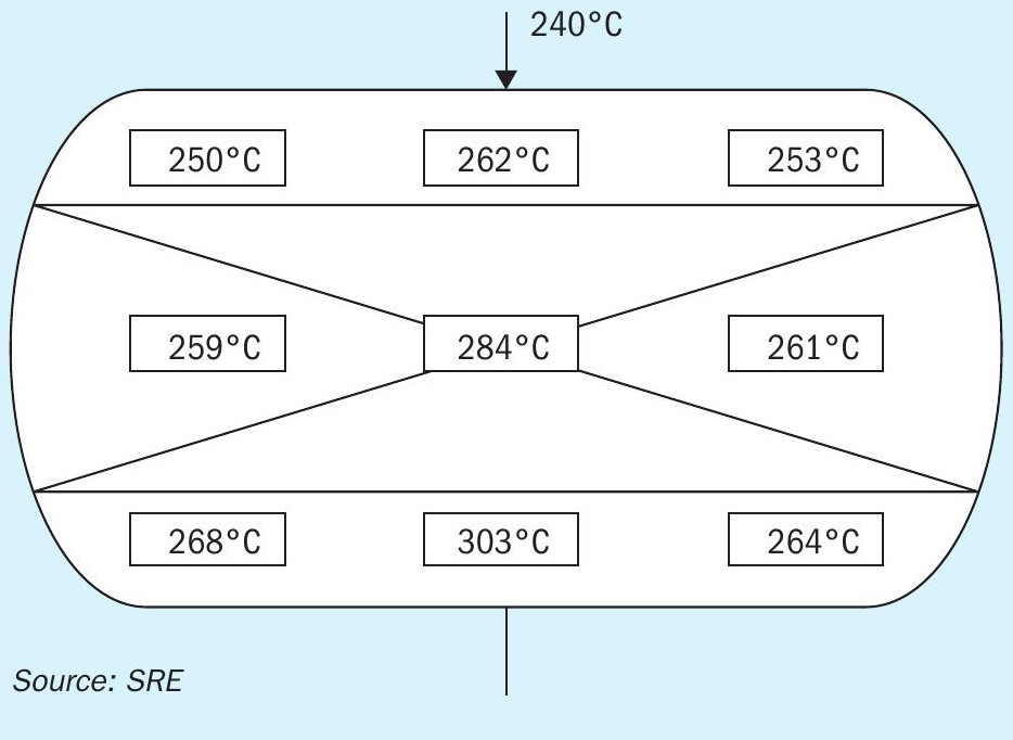
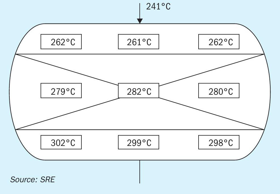
The converter bed illustrated in Fig. 1 showed large variation in spot temperatures throughout the converter bed as well as reduced overall conversion rates across the converter. Both of these signs strongly indicated the occurrence of channelling within the catalyst bed. By modifying the deflector plates to direct the inlet flow more evenly across the bed a much more even temperature gradient throughout the catalyst bed was achieved (Fig. 2).
While rearrangement of inlet deflector plates and an increase in the number of entry points can help create a more turbulent inlet flow, reducing the likelihood of channelling, it does not address the decrease in pressure drop across the bed.
Reducing the catalyst size can create a more densely packed bed, resulting in a higher pressure drop under lower flow conditions, which would decrease the effects of channelling. In addition to this, isolating a portion of the bed from the inlet flow would result in a smaller bed area for the same inlet flow, which would also theoretically increase the pressure drop across the bed, again decreasing the effects of channelling.
Condensers
Turndown conditions result in lower volumetric flow rates into the SRU, and this in turn results in lower internal flow velocities inside the condenser tubes, which can result in both liquid sulphur entrainment and sulphur fogging. Both of these circumstances lead to the condenser not operating correctly, and can negatively affect the SRU as a whole. In extreme cases, sulphur entrainment could lead to catalyst bed contamination, and uncontrolled sulphur fires.
Fig. 3 shows the adverse effects on a final condenser caused by the SRU operating at a highly reduced operating capacity.
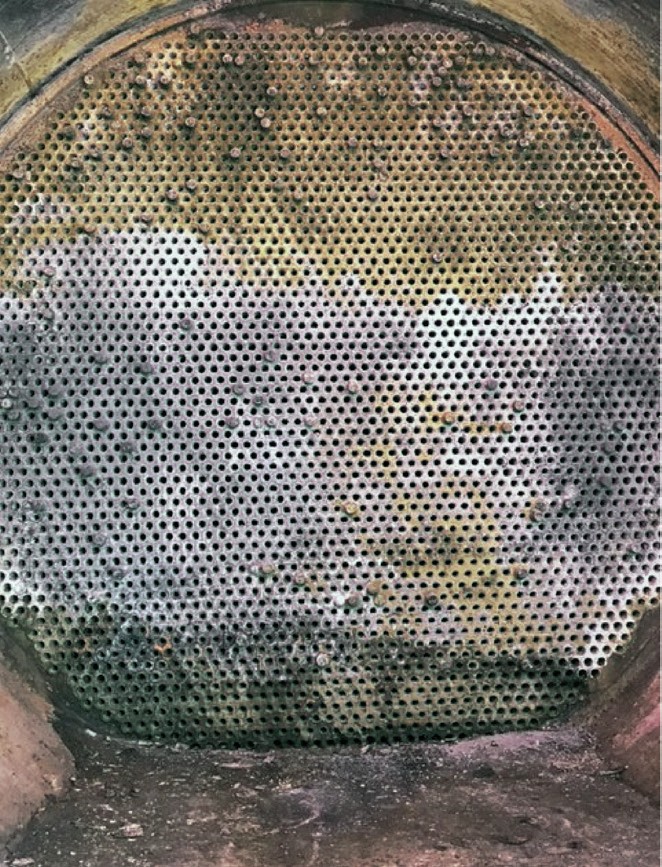
The most effective solution to prevent these problems is the systematic plugging of a number of condenser tubes, to maintain a constant cross-sectional velocity across the tubes.
Acid gas knockout drum
In turndown conditions, the instrumentation and piping for the acid gas knock out drum should remain largely unaffected by the changes in volumetric flow rates. However, the mesh pads within the vessel can only be assumed to perform adequately down to 40% of design capacity. Below this, it may be necessary to redesign and/ or replace the pads to better suit the associated downturn flow rates.
This is due to the fact that at lower flow rates into the vessel, the pressure drop at the nozzle decreases, which in turn decreases the rate of flashing upon entry to the vessel.
In order to counteract the loss in pressure drop at the nozzle a larger number of mesh pads could be installed, or the existing mesh pads could be resized to account for the lower pressure drop and higher residence time within the vessel.
Combustion air blowers
Combustion air blowers are theoretically capable of performing adequately under any level of turndown, assuming proper surge protection is in place, and the blower has undergone mandatory reviews.
Turndown of an SRU could be due to a decrease in overall inlet gas flow rates, with acid gas quality maintained, or the inlet gas flow rates could remain constant, but the overall acid gas quality could drop. The coexistence of both of these factors should also be considered. In all of these situations, the result is a drop in overall volumetric flow into the system, which in turn has cascading effects on the entirety of the SRU.
In the case of high turndowns, venting volumes can become quite large, resulting in a drop in operating efficiency, and an increase in operating costs.
Complete blower replacement should be strongly considered at high turndown rates, to offset increases in operating costs associated with high venting losses.
In addition, proper review and comparison with design blower air capacity should be performed in order to evaluate the suitability of the existing air blower to adequately operate under lower inlet flow rate conditions.
Air flow control
In the case of turndown, the reduction in overall volumetric flow into the SRU must be accounted for within existing air flow control methods. The sizing of the main air line is based on the expected design capacity, and therefore is not as effective or efficient if the overall volumetric flow rate decreases. If volumetric flow rates drop below roughly 30% normal operating levels, it is likely necessary to replace existing orifice plates within the SRU with equivalent plates sized to more effectively and accurately handling the lower rates.
The different types of valves used in air flow control react differently to turndown conditions, in terms of efficiency of operation. In this situation, the butterfly valve is poorly suited for large changes in inlet flow rates, while the globe or ball valve is relatively better suited, and the V-ball valve performs best under varied conditions.
It is highly recommended to perform dynamic modelling of the SRU to identify whether making adjustments to the existing air flow control valves will be adequate for handling the reduced flow rates, or whether it is necessary to replace them with more effective valve types.
Waste heat exchanger
During turndown, lower inlet flow rates can result in a decrease in the outlet temperature of the reaction furnace/waste heat boiler. It may be necessary to plug a number of the waste heat exchanger tubes in order to maintain or increase the internal velocity and raise the outlet temperature above the process dew point.
This will help maintain a constant outlet temperature from the waste heat exchanger, reducing the likelihood of sulphur entrainment within the system, as well as maintain consistent flow in the sulphur condensation rundown lines.
Direct fired reheaters
Typically, during turndown, burner rates in the reheaters are firing at roughly 35% normal operating capacity. This reheater turndown rate is not directly proportional to the SRU turndown rate, due to heat losses in the system, as well as lower condenser outlet temperatures.
If the burner rate requirements in the SRU reheater(s) drop to below 35% design capacity, replacement of the burner and its associated instrumentation is recommended.
Some advanced burners are capable of handling higher turndowns, as they are adjustable, and it may be worthwhile to initially install an advanced burner to reduce the effects of turndown when they arise.
In addition, alternative reheating methods such as steam are often better suited to handle higher turndown rates, with the exception of gas-gas exchangers.
Incinerator
In the case of turndown, the lower expected flow volumes may result in flow measurement and plume dispersion problems. While increasing dilution air may counteract this volume reduction, it in turn results in higher fuel costs, as well as a larger environmental impact in the form of SO3 and NOx emissions.
Considering the notable variability of all of these phenomena, there is no accurate predictive model which can evaluate these parameters.
In order to increase stack exit velocities, it may be necessary to introduce a stack exit cone or stack liner. Both of these solutions reduce the residence time within the stack and thus reduce the overall formation of SO3 and NOx emissions.
Case study 1: Reaction furnace performance
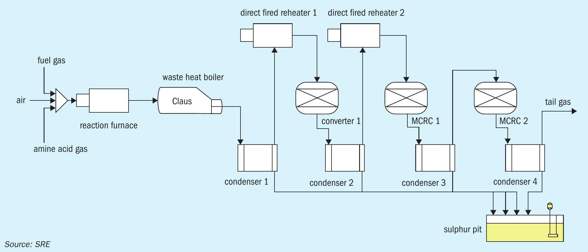
This case study focuses on a southern Alberta gas plant, operating an SRU with an initial design capacity of 100 t/d. The SRU was operating a 3 -stage configuration consisting of a single modified-Claus converter followed by a 2-converter MCRC sub-dewpoint unit (Fig. 4) and then a thermal incinerator for further processing of the tail gas stream from the MCRC bed in adsorption.
Due to turndown conditions, the plant was running at a much lower rate of 10 t/d, using fuel gas co-firing and an acid gas front side split configuration in order to maintain reaction furnace temperature, as well as an adequate H2 S to SO2 ratio.
The facility was planning to operate the unit at even lower turndown conditions of roughly 5 t/d. They contacted Sulfur Recovery Engineering (SRE) to perform baseline studies for these expected conditions, however the facility was unsure about the performance of CFD prediction models in regard to the reaction furnace.
In order to avoid a complete replacement of the existing burner, SRE was consulted to conduct performance testing on the unit while operating at 5 t/d. To perform these tests, SRE conducted them while one of the compressors was down, effectively mimicking lower operating conditions expected in the future.
At the lower production rate, the facility’s sulphur recovery license requirement was 95.9%. In addition to the lower production rate, a reduction in overall acid gas quality was expected, dropping from their usual value of 60% H2 S (dry basis) down to 12%. Due to both the lower production rates and quality of inlet acid gas, the reaction furnace main burner was operating with co-firing of natural gas in order to maintain high enough temperatures to adequately remove BTEX components in the reaction furnace. In order to maintain adequate H2 S:SO2 ratio, an acid gas split stream was introduced to the second zone of the reaction furnace.
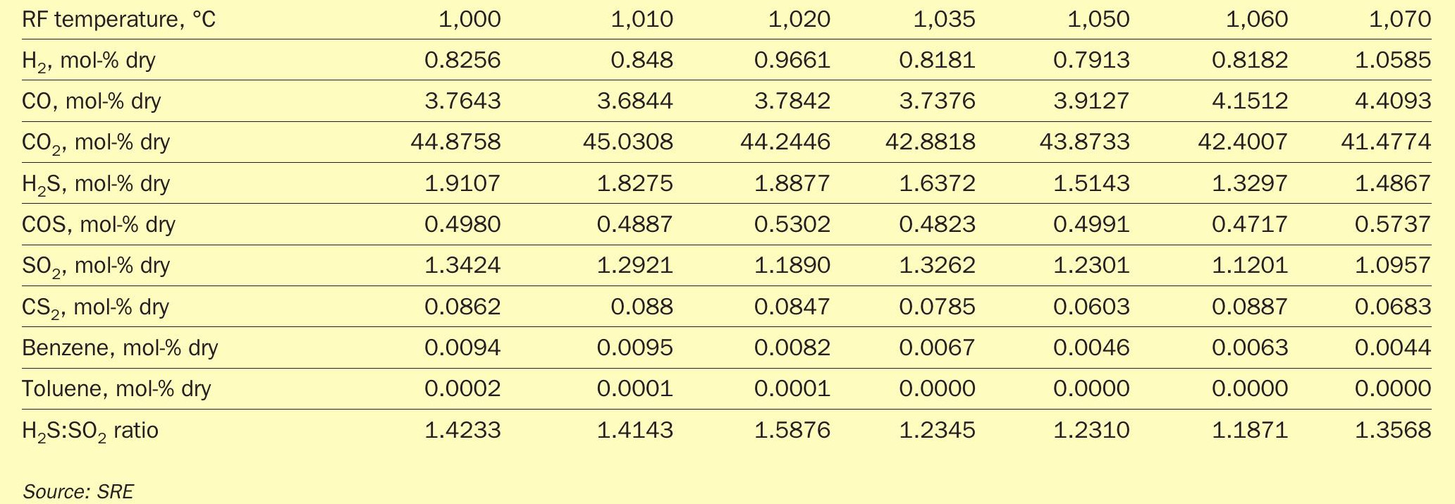
SRE conducted several tests in regard to co-firing and split configuration flow ratios, in order to fine-tune the best possible scenario in which to operate at 5 t/d. The factor of priority was ensuring that the reaction furnace would still be able to effectively destroy contaminants while maintaining a satisfactory H2 S:SO2 ratio (Table 1).
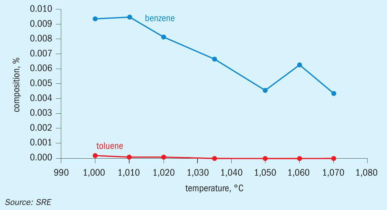
As shown in Fig. 5, toluene breakthrough was entirely eliminated once temperatures reached a minimum of 1,020°C. Benzene breakthrough was present throughout the testing, but was considered to be minimal, and posed a very low risk to the catalyst.
The H2 S:SO2 ratio was considerably lower than the optimal ratio of 2:1, at a range of roughly 1.2 to 1.6. This result was anticipated however, as the co-firing required to maintain furnace temperatures resulted in a higher than normal conversion rate of H2 S in the reaction furnace. This lower H2 S:SO2 ratio was remedied by introducing the acid gas split stream to the second zone of the reaction furnace. In implementing this stream, we were able to achieve results that met all licensing requirements.
This approach was much better than solely relying on a predictive model, and SRE was able to determine that it was indeed possible to operate the plant at the lower predicted tonnage while still meeting satisfactory regulatory conditions.
The trace amount of benzene breakthrough was a notable concern due to its role in catalyst poisoning.
However, SRE was assured by the catalyst provider that breakthrough quantities below 100 ppm of benzene would not have any serious effects on the catalyst.
Case study 2: Repetitive hydrocarbon upsets to the SRU
In this case study, performed by Optimized Gas Treating (OGT), turndown was found to reduce dewpoint margin inside a refinery HDS contactor and degrade the quality of the acid gas. Amine units without rich amine flash drums have higher consequences in addition to being more susceptible to upsets.
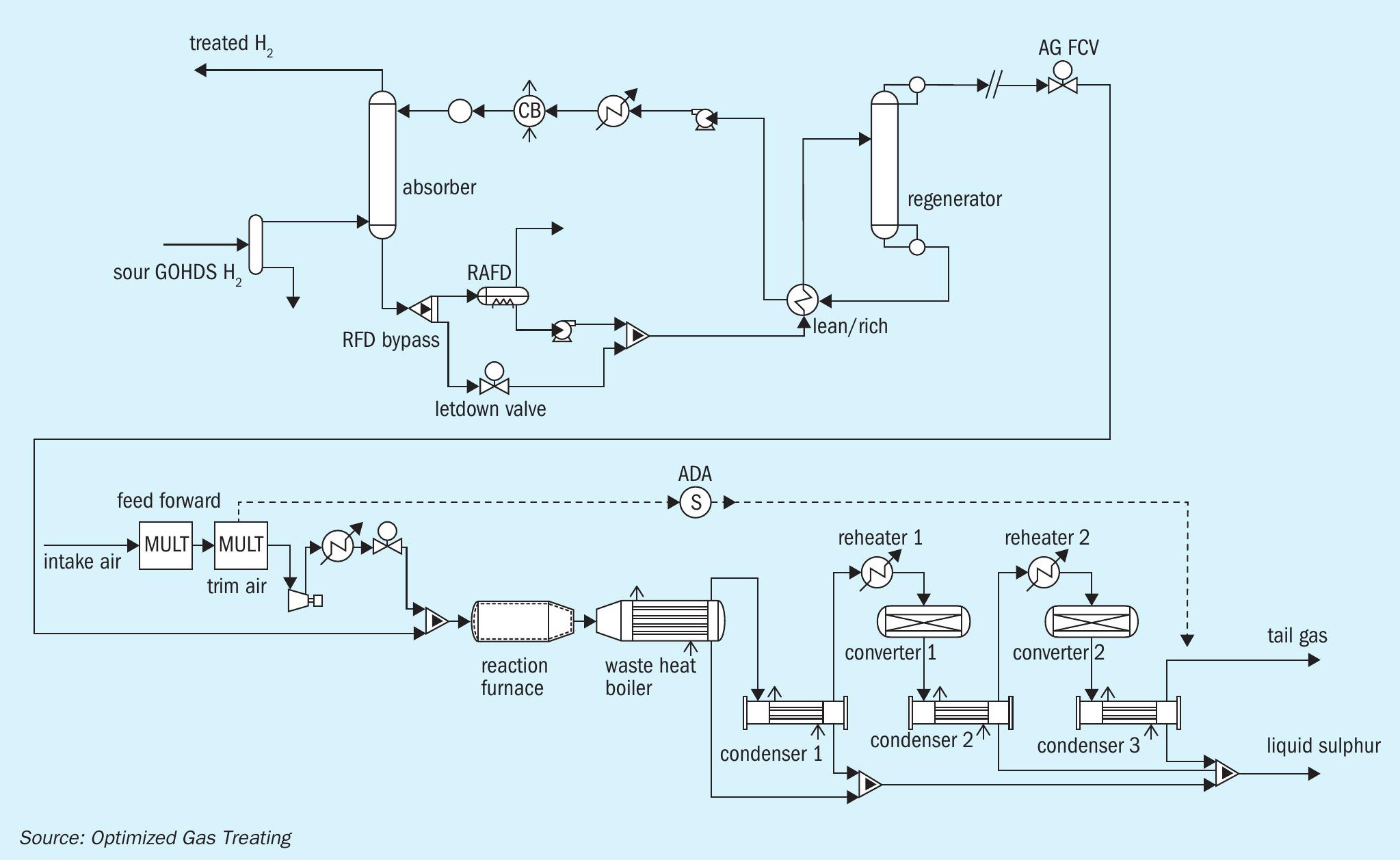
This case study refers to a refinery sulphur processing train treating mainly HDS gas. The system uses 45 wt-% MDEA to treat 200 million std ft3 /d of recycle hydrogen containing normally 1.2% H2 S from a gas oil hydrotreating system (GOHDS). A multidiscipline root cause analysis (RCA) team was commissioned to investigate repetitive hydrocarbon upsets to the SRU. Within this plant, upsets historically occurred every HDS start-up. A sister refinery with no rich amine flash drum (RAFD) installed experienced the same problems with worse consequences. This study assesses the impacts and ramifications of both scenarios for an upstream amine unit with and without a RAFD.
Fig. 6 shows a SulphurPro® and Pro-Treat® seamlessly integrated flowsheet for a refinery sulphur processing train treating HDS gas.
Case study results
On start-up, the lighter oil (distillate) feedstock together with the lower HDS operating pressure were found by simulation to produce more heavy hydrocarbons in the feed to the amine contactor. The upstream separation equipment was designed for HDS recycle flow at higher operating pressure (900+ psig vs. 550-600 psig start-up operation). Separator calculations at the lower operating pressure found the system to be inadequate. These factors were the root causes for liquid slugs of hydrocarbon entering the amine system.
On a more subtle note, considerably less H2 S was present in the amine contactor feed processing start up distillate versus the normal gas oil feed. The RCA team found that the amine contactor could be bypassed for a major portion of the start-up. The systems were modelled postmortem using ProTreat® and SulphurPro® simulation at 30% turndown operation to mimic HDS start-up on a lighter oil.
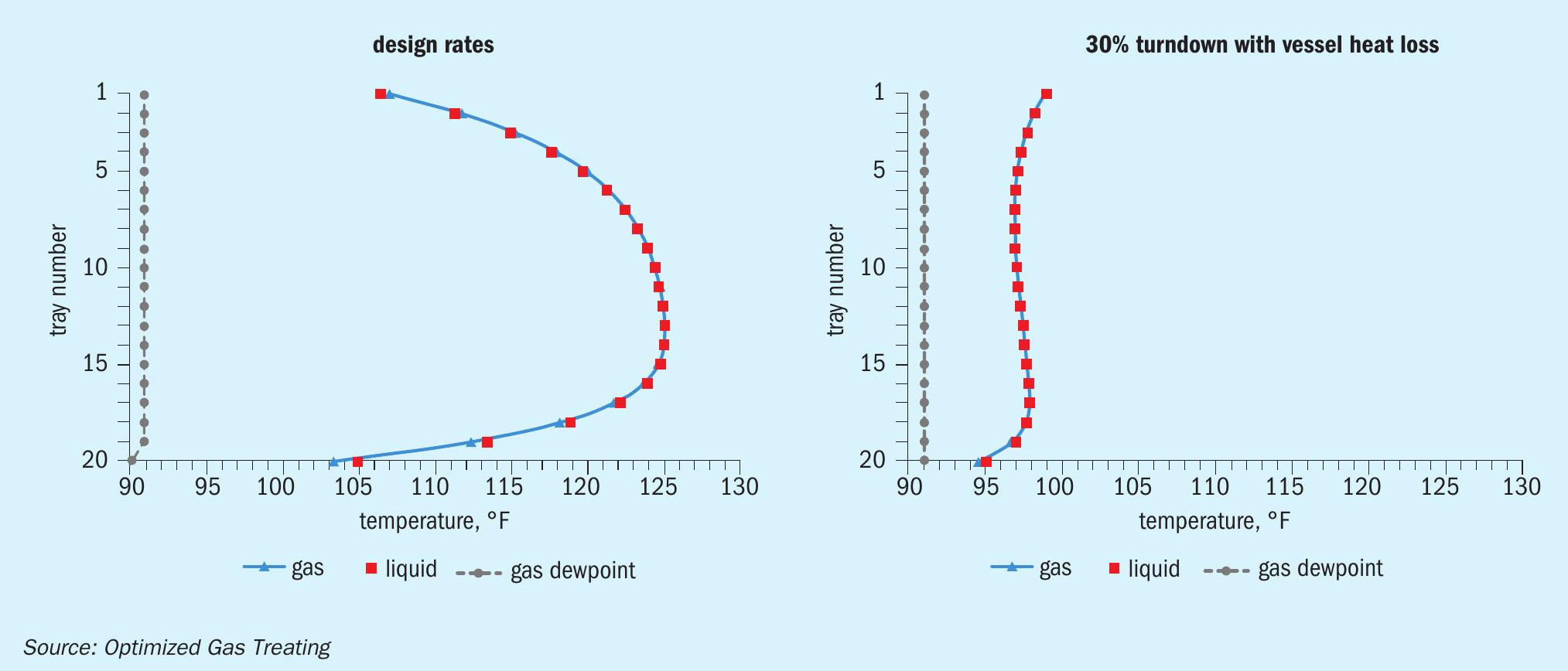
With 30% of design H2 S in the feed, ProTreat identified that absorber column internal temperatures are much colder at turndown and closer to the dry gas dew point as seen in Fig. 7. The heat loss from the turndown lowers the dewpoint approach temperature by an additional degree. The 13°F dewpoint approach at design drops to only 3-4°F at turndown. With this dewpoint approach, even minor hydrocarbon inlet liquid entrainment can be expected to result in major problems in the amine and Sulphur recovery units.
In addition to analysing the operations, the economics and a few performance metrics related to lost hydrocarbon product were also evaluated. Table 4 shows that hydrocarbon content in the acid gas increases nearly six-fold for turndown rates compared to design. The ramifications here are:
- Feedforward air ratio control in the SRU will be off 1-5% at turndown versus design. While this is not a huge amount, it is enough to significantly impact the TGU reliability (SO2 breakthroughs) if the feedback air demand analyser has problems. Here there would be value in having a rich amine flash drum.
- There is an economic penalty to burning hydrocarbon in the SRU versus leaving it in the money-making hydrocarbon units that amounts to the value of roughly a new pickup truck. The larger penalty that cannot be as easily quantified is the lost SRU capacity from reliability downtime.
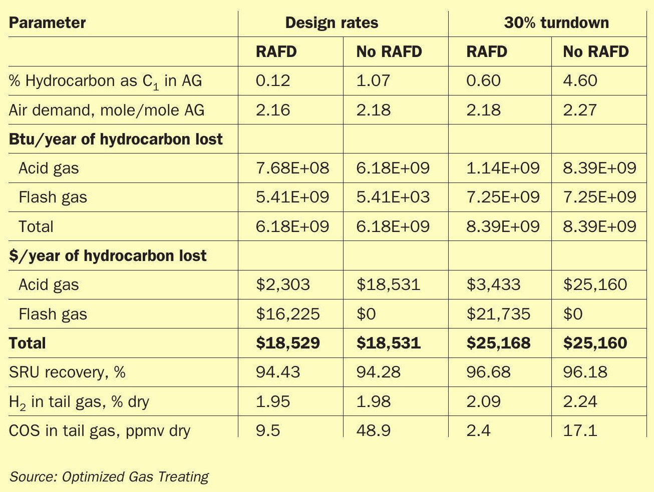
Table 2 also shows improved SRU recovery at the turndown conditions. This is due to more residence time in the Claus catalyst at the decreased rate. Looking at the Claus reaction approach to equilibrium in the second converter, the design case is at 59.5% while at turndown the equilibrium approach is 95.5%. As developers of the kinetic rate-based Claus Converter in SulphurPro® , OGT questioned whether this was valid data or a bug in the software. After comparing the reactor conditions versus plant performance test data for similar applications, this effect appears to be real. However, the observations are not universal to all situations. The dependence upon rates, temperature, and degree of catalyst aging can be quite touchy. In fact, the second converter in this case operates cooler than many plants in an area where Claus reaction equilibrium is more favourable, but kinetics are slower than at higher operating temperatures.
Case study 3: Turndown of the SemCAMS KA gas plant SRU
The SemCAMS Kaybob Amalgamated (KA) gas plant was originally designed with two sulphur recovery units (SRUs), each designed to process 550 t/d of sulphur which were followed by a common Sulfreen unit designed for 1,100 t/d of sulphur. Due to declining sour gas reserves, SemCAMS was predicting that the processing capacity of the one remaining SRU in operation would need to be reduced to 50 t/d of equivalent sulphur in the feed gas. Simultaneously SemCAMS predicted that the acid gas composition would be reduced from 70 mol-% H2 S to a minimum expected value of 50 mol-% H2 S. The overall sulphur recovery had to be maintained above 98.6%.
Comprimo was contracted to evaluate options for SemCAMS to handle the lower sulphur tonnage and predicted leaner acid gas. During this evaluation, equipment modifications, changes in operating parameters and catalyst replacement were considered to allow the plant to process the new acid gas flow rates and compositions while still maintaining the overall regulatory sulphur recovery efficiencies. In addition, the ability to be able to start up with the lower acid gas flow rates and composition were considered to determine whether additional gas needs to be brought in during start-up to ensure the heating of the converter beds.
The existing sulphur recovery unit was a three stage Claus unit which was followed by a Sulfreen unit achieving an overall sulphur recovery efficiency of 99.0%. The configuration of the sulphur recovery unit was provided in Fig. 8.
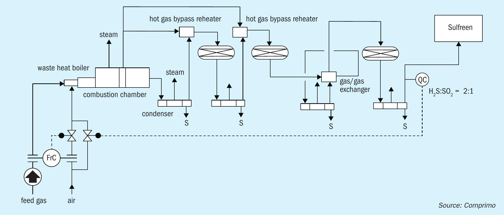
The plant was made up of a thermal stage, consisting of a high intensity HEC burner followed by a water tube waste heat boiler (WHB), which produced 27.5 barg (400 psig) steam. The waste heat boiler was a two pass design and the gas from the first pass was used to reheat the gas into the No. 1 and No. 2 converters via hot gas bypass valves. The gas from the second pass of the waste heat boiler was routed to the thermal condenser. The No. 1 and No. 2 converters contained alumina catalyst and were operated at higher temperatures than usual due to the hot gas bypasses and gas/gas No. 3 reheater. The inlet gas to the No. 3 converter was reheated in a gas/gas exchanger in which the outlet gas from the No. 2 converter was cross exchanged with the outlet gas from the No. 3 condenser. Each stage was equipped with a condenser that produced 3.5 barg (50 psig) steam. The tail gas from the unit was routed via a long tail gas line to the existing Sulfreen unit. The Sulfreen unit was originally designed as a four bed system, however was operated by SemCAMS as a three bed unit at the time of the study.
Comprimo was requested to determine the minimum possible processing capacity of the plant based on the predicted future acid gas composition. A target capacity for the study was set at 50 t/d of sulphur production. Additionally SemCAMS wanted to determine what the minimum required acid gas supply would need to be to properly start up the unit from cold conditions with the proposed future configuration for the unit.
Study parameters and requirements
The study parameters and requirements set by Comprimo and SemCAMS were to determine the modification to the plant required to minimise the turndown of the plant while maintaining:
- Overall sulphur recovery efficiency per the Alberta regulations
- Operation of the unit above sulphur dewpoint
- Capability to start up the unit cold with the low acid gas rates
- Minimum capital investment
- The overall sulphur recovery target for the study was set at 98.6%.
Study results
The obvious limitation of the plant to operate at high turndown was the reheater configuration. Based on the plant’s operating experience, the minimum processing capacity of the unit at the start of the study corresponded with approximately 120 t/d.
As a first step it was essential to determine the actual turndown limitations of the plant. It was concluded that with the current configuration it was not possible to turn the unit down to 100 t/d.
The following options were therefore considered to allow the plant to process the expected future sulphur processing capacity:
- install a new 100 t/d SRU;
- replace the second and third reheater with steam reheaters;
- use co-firing with natural gas to increase the mass flow through the unit and use titania catalyst to counteract the higher formation of COS and CS2 .
New SRU
The first option to install a new 100 t/d SRU that was able to meet the required 98.6% sulphur recovery was estimated to cost approximately $25-30 million. As a conventional three-stage Claus unit would not be able to meet the required sulphur recovery efficiency, a new 2+1 SUPER-CLAUS® unit was considered as the basis for the evaluation. The cost of this option was deemed too expensive by SemCAMS so this option was eliminated without much review. This option would also limit the plant preventing a return to higher capacities in the future in case new sour wells would be added to the plant.
Reheater replacement
As the key limitation of the plant’s turndown capabilities appeared to be its configuration, Comprimo evaluated the option to replace the second and third reheaters with steam reheaters. In addition, two options were considered to increase the thermal reactor temperature to deal with the higher BTEX concentration in the acid gas:
- co-firing natural gas with the current configuration;
- installation of steam heated acid gas and air preheaters.
Based on the available models in the simulators used (Promax and Comprimo simulator), it became evident that it would not be possible to meet the required sulphur recovery efficiency with the co-firing option. The option to co-fire to maintain the thermal reactor temperature for proper BTEX destruction was therefore initially discarded.
The estimated cost for the replacement of the first and second reheaters and the installation of an acid gas and air preheater was $9 million, which was again in excess of SemCAMS’s expectations and Comprimo was requested to further evaluate alternative options.
Co-firing with catalyst replacement
From the evaluation of the waste heat boiler performance, it became clear that in order to maintain a temperature that was sufficiently high from the first pass of the WHB for the hot gas bypass reheaters, the mass flow would have to be increased through the exchanger. As the waste heat boiler was a water tube boiler it was not possible to plug tubes as would be the case for a fire tube design. It might have been possible to remove tubes from the exchanger, however this option was not further pursued as this action would likely be irreversible. Therefore Comprimo evaluated how a minimum mass flow through the unit could be maintained under all turndown scenarios. By maintaining a minimum mass flow through the unit, the outlet temperature from the No. 2 converter would have been sufficiently high to enable the gas/gas exchanger to maintain the No. 3 converter above the sulphur dewpoint. In order to increase the mass flow, co-firing with natural gas could be used, as it required additional air for the combustion of the natural gas component.
To understand the impact of natural gas co-firing at the KA gas plant, Comprimo had the most recent performance test report data available, in which the overall sulphur recovery efficiency was evaluated for both normal operation and with the addition of natural gas co-firing. This data proved very useful, as it indicated that the overall sulphur recovery was heavily impacted by the introduction of natural gas co-firing and it was clear that the sulphur recovery efficiency target could not be met with the current configuration with co-firing with natural gas.
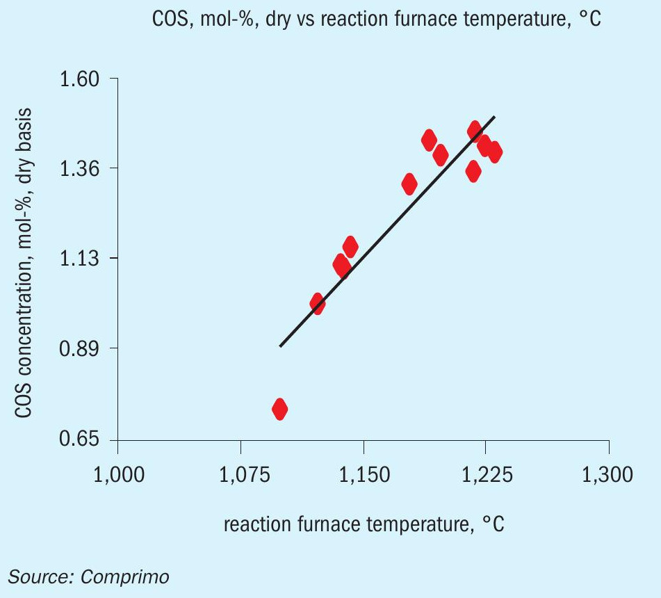
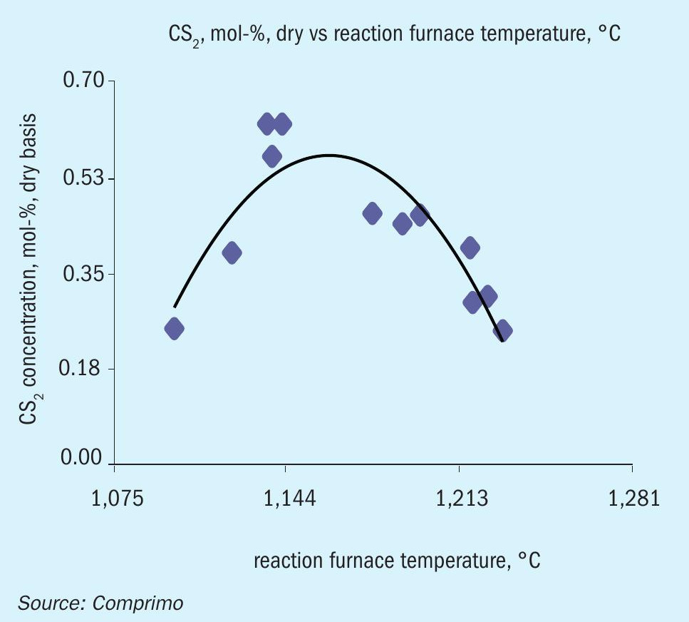
Although it is well known that operation with co-firing will result in additional formation of COS and CS2 , the exact increase of these components is hard to predict and varies widely in commercially available simulators. A test programme was therefore set up for the plant to determine the relationship between the level of co-firing and the formation of COS and CS2 in the reaction furnace.
A sulphur plant testing company was brought in to sample and analyse the gas streams in the Claus unit while operating the unit in turndown with different levels of co-firing. The results of the testing are provided in Figs 9 and 10. It was determined that COS increases as a function of increased natural gas co-firing, however CS2 goes to a maximum as a function of temperature.
The test data indicated that when co-firing was considered to increase the mass flow, there was a definite impact on the overall sulphur recovery efficiency of the plant to the point where the regulatory requirements would no longer be met. Therefore it was clear that co-firing alone would not meet the requirement to meet both the capacity and the overall sulphur recovery targets for the SemCAMS KA gas plant. As a result it was decided to evaluate the option to install titania in the Claus unit in order to meet the sulphur recovery requirements.
Comprimo contacted Axens to discuss the potential of using titania catalyst in the No. 1 and No. 2 converters to counteract the effects of the formation of COS and CS2 in the thermal reactor during co-firing. The information supplied by Axens suggested that a COS hydrolysis of 98% and 96% for No. 1 and No. 2 converters respectively and CS2 hydrolysis of 92% and 75% for No. 1 and No. 2 converters respectively could be met when the catalyst beds in both converters are replaced with a 25% alumina/75% titania bed.
Comprimo estimated that for the case where sufficient natural gas co-firing was added to maintain the WHB at the minimum turndown mass flow, and replacing the catalyst as described above, a sulphur recovery of 98.7% was expected, i.e. still above the target level of 98.5%.
In discussion with Axens, the decision was made to install a 85/15% split alumina/titania catalyst bed in the No. 1 and No. 2 converters, which would be adequate to ensure high COS and CS2 hydrolysis. The expected values for the hydrolysis were 97% and 88% for COS and 89% and 55% for CS2 in the first and second bed respectively, which depending on the capacity of the plant would still result in an overall recovery between 98.7% and 98.9% for a capacity of 70 t/d to 120 t/d.
One of the items that was identified as a potential concern with the installation of the new catalyst configuration was the low space velocity in each of the converters due to the large size of the unit. Low space velocity in a catalyst bed can result in channelling of the gas through the bed. In order to overcome this concern, Axens proposed the installation of a smaller bead size for the CR-3S alumina catalyst (2-3 mm), resulting in a higher pressure drop and thereby better distribution of the gas.
The high intensity burner installed on the thermal reactor was also evaluated for operation in co-firing mode. As back burning is typically a concern with burners in turndown operation, the addition of co-firing was found to be beneficial to the operation of the burner. With co-firing the air demand of the burner is increased as well, resulting in a higher pressure drop across the burner. Therefore as long as the control system was able to handle the required natural gas flow rates, the burner was not going to be a concern. Based on Comprimo’s evaluation, the limitation of co-firing was not in the sizing of the equipment, but in the limitation of the installed refractory. Co-firing results in higher temperatures in the thermal reactor and although this has benefits for contaminant destruction, the amount of co-firing was limited by the refractory maximum service temperature.
The total estimated cost of the installation of new catalyst in the converters was less than $1 million.
Testing of the selected option
The new catalyst configuration was installed in the converters and the performance of the sulphur plant was tested to determine the impact of the installation of the new catalyst together with co-firing operation.
The data from the September performance test showed promise in the ability to turn the plant down to approximately 80 t/d, so it was decided that a further test needed to be done to truly operate under these turndown conditions. Therefore the plant blocked in several of the sour wells supplying the plant, thereby being able to reduce the capacity of the plant to about 60 t/d equivalent. The intent of the test runs was to determine the limiting parameter when the plant was turned down.
Based on the results from the tests, Comprimo deduced that the possible turndown of the KA gas plant SRU was a function of the acid gas composition. When the acid gas became leaner, it was possible to increase the amount of co-firing until the limitation of overall sulphur recovery was met, whereas with a higher acid gas H2 S concentration, the first limitation was the refractory temperature. Therefore, Comprimo concluded that the following minimum capacities could be attained with the new catalyst configuration using co-firing to maintain the mass flow through the unit:
- At 65% H2 S in the acid gas the minimum processing capacity of the unit was 65 t/d
- At 50% H2 S in the acid gas the minimum processing capacity of the unit was 48 t/d.
Three years of studying and testing
Comprimo started with a turndown target from SemCAMS and initial performance data that was based on a much higher capacity than the predicted future capacity. Based on this information the initial recommendations were made, which led to a requirement for further performance testing to determine whether these recommendations were attainable. It was found during the study that the best way to come up with a predictive model for a plant was to tie the simulation results of the model with the data from operating and performance test data. By progressively testing of the facility and simulating the results of these tests, Comprimo was able to narrow down the results to come up with a more accurate prognosis for where the plant could operate in the future and how low the turndown of the plant actually could be. This proved to be substantially different than the originally predicted values.
It was concluded that it should be possible to reduce the capacity of the plant to a capacity of 50 t/d with co-firing at reduced acid gas concentrations. At higher acid gas concentrations, the actual turndown was limited by the maximum limitation on the refractory of the thermal reactor.
By installing Axens titania catalyst and improving the capability of the No.1 and No. 2 converters to hydrolyse the COS and CS2 formed in the thermal reactor during co-firing, it was possible to consider co-firing for the unit to maintain a minimum mass flow through the unit and thereby overcome the limitations of the installed gas/gas exchanger as the No. 3 reheater. This minimised the cost of the modifications substantially and allowed the plant to remain in operation. In addition the performance test work allowed Comprimo to estimate the required acid gas that was necessary to be able to bring the unit from a maintenance turnaround to steady state operation. This allowed SemCAMS to plan ahead of time the amount of raw gas that needed to be supplied to the gas plant to ensure a smooth and successful start-up, before the capacity can be decreased again to the predicted turndown.
Some additional potential future limitations were discovered that would need SemCAMS’ attention before the minimum turndown can be achieved. These mostly related to the Sulfreen unit which was very large compared to the future processing capacity of the unit.
Case study 4: The burning tail gas line
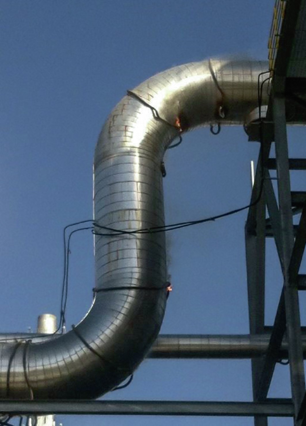
The plant configuration for this case was a large four-stage EUROCLAUS® unit (also called a 3+1 EUROCLAUS® unit). The plant had been processing acid gas for some time already. After a trip of the unit, the plant was put on hot standby operation. It was during this time that flames were observed to be coming out of the cladding of the tail gas piping to the incinerator. The tail gas line had been installed with ControTrace® to maintain the wall temperature of the piping above the freezing temperature of sulphur (118°C) and was insulated. The tail gas pipe was sprayed with water to extinguish the fires and the plant was returned to acid gas operation. After a subsequent trip, a similar incident occurred, and a second fire was observed. In Fig. 11, small orange flames can be observed coming out of the cladding around the insulation in several locations.
Upon shutdown and removal of the cladding and insulation, it was found that the tail gas piping was deformed and showed indication of a fire on the outside of the piping. No indication was found of a loss of containment of the piping.
As under normal conditions there is no combustible mixture in the tail gas, the initial thought was that the heat transfer cement had caught fire after the transition from acid gas firing to fuel gas firing, however tests done in the Ametek CSI labs (who designed and supplied the ControTrace® ) indicated that a temperature of 400°C is required to ignite the heat transfer cement. This meant that the tail gas piping needed to have been heated to a temperature of over 400°C in order to be able to ignite the heat transfer cement. Per discussion with CSI, there was some evidence though that the installers of the ControTrace® had added a solvent to the heat transfer cement to make the material smoother for easier installation, which very likely decreased the auto-ignition temperature of the heat transfer cement.
As there was no acid gas in the plant at the time of the fire, the main culprit was deemed to be related to the hot standby operation. Based on the available DCS information at the time of the incident, Comprimo determined that during the hot standby operation the plant had been operating with a combustion in the order of 80% stoichiometry without the introduction of steam for moderation. Using this data, Comprimo estimated that the tail gas (that was bypassing the final selective oxidation reactor) contained approximately 5% CO and 4% hydrogen. In addition, due to the normal operation of a EUROCLAUS® unit requiring air addition for the final stage as well as the introduction of vent air from the sulphur pit degassing unit, oxygen would have been present in this gas stream as well. Comprimo believes that due to the very low stoichiometry of the natural gas firing, sufficient combustible material was available in the tail gas piping to light off the gas by the incinerator (as the ignition source) thereby resulting in a fire in the tail gas piping. With a fire in the tail gas piping during hot standby, when the gas velocities were relatively low (especially with no moderating steam), the temperature of the tail gas piping gradually increased, resulting in the auto-ignition of the heat transfer cement with the diluent material.
The main lesson learned from this experience was that the stoichiometry during hot standby operation can play a substantial role in a SUPERCLAUS® /EUROCLAUS® unit due to the presence of air downstream of the final reactor. This could also be the case for a plant that introduces the vent air from a sulphur pit in the tail gas piping upstream of the incinerator. It is very important to have good measurement of all feed streams flows into the main burner of the SRU, which means pressure and temperature compensation on all streams, as well as a good analysis of the fuel gas/natural gas used for start-up and hot standby operation. The installation of an onstream analyser for the fuel gas/natural gas can also be considered in order to have an onstream adjustment of the stoichiometric air to FG/ NG ratio, thereby ensuring that both excessive substoichiometric and super stoichiometric combustion of the fuel gas/natural gas does not occur.
In addition, it was clear from the information that the installers had used a solvent to make the installation of the heat cement easier and that it is essential to have proper training and supervision of the installation of the ControTrace® elements as in this case it led to ignition of the heat transfer cement.
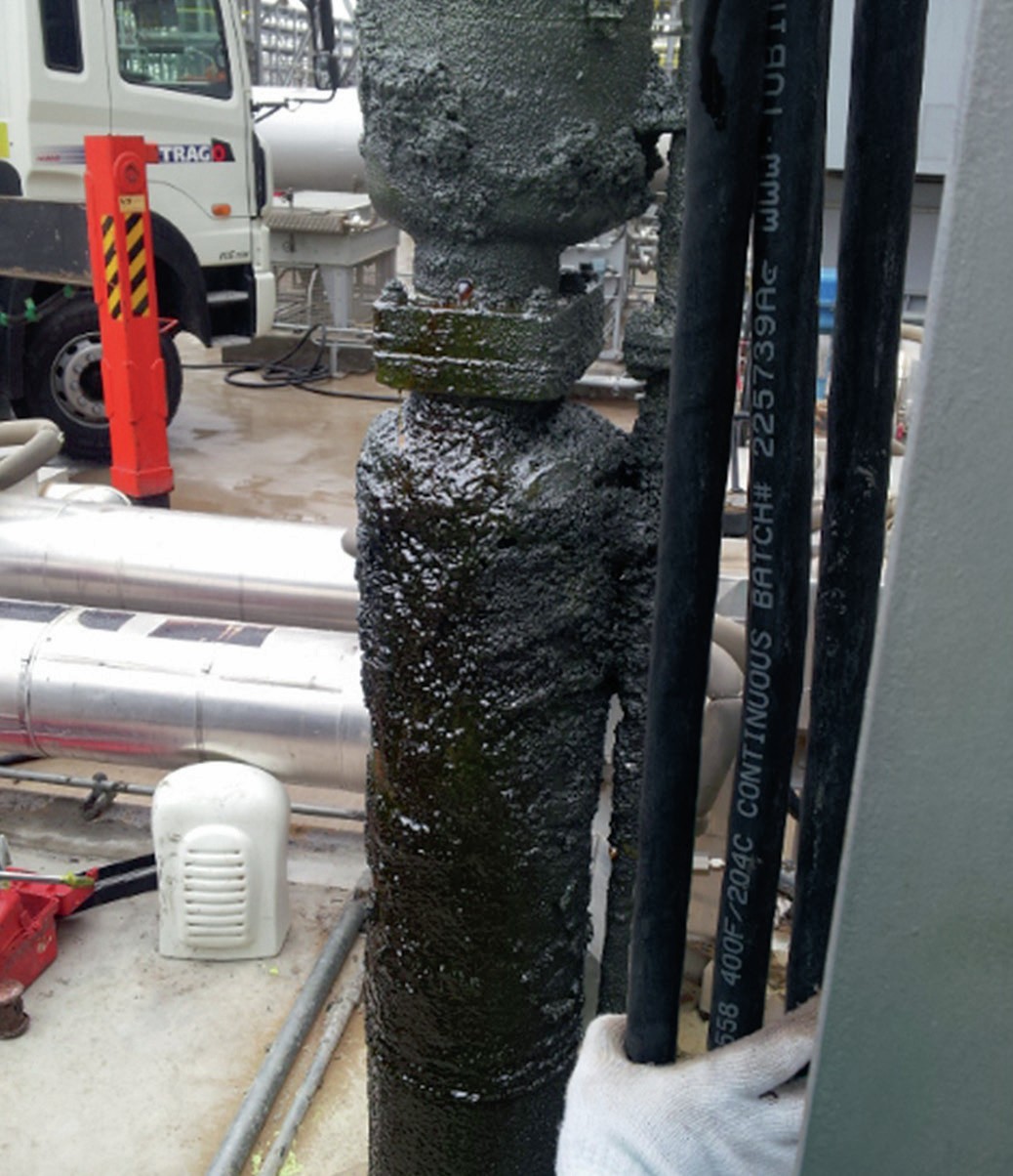
Anecdotally, upon removal of the sulphur pumps from the sulphur pit, the sulphur pump appeared to be covered with a substantial amount of CarSul (Fig. 12), which could indicate that the combustion of the natural gas was more sub-stoichiometric than previously suspected or heavier hydrocarbons than expected were present in the natural gas.
References