Sulphur 426 Sep-Oct 2026
17 September 2026
Engineered heat tracing for sulphur safety
SULPHUR SAFETY
Engineered heat tracing for sulphur safety
Molten sulphur systems demand precise temperature control to prevent solidification, rising viscosity and the build-up of hazardous vapours. Carefully engineered heat tracing for pipework, storage tanks and vapour spaces is therefore critical to maintaining safe, reliable operations. It helps mitigate the risks of blockages, overpressure, toxic exposure and ignition. Kent Snelson of QMax Industries sets out the safety case for correctly heated sulphur systems.
Molten sulphur is among the most demanding services in the refining industry. Although the objective appears straightforward – keep sulphur above its melting point and maintain flow – the acceptable operating range is narrow. Missing it can create serious safety risks, from blocked and pressurised lines to the release of toxic and flammable hydrogen sulphide (H₂S) vapour.
Heat tracing on sulphur piping and vessels is therefore not simply a maintenance consideration. It is an engineered safety system.
A narrow operating window
Sulphur freezes just below 240°F (116°C), with crystallisation beginning at around 246°F (119°C). As temperatures approach this threshold, viscosity rises, flow slows and a cooled section of pipe can solidify within hours.
A frozen sulphur line is not a simple restart issue. Uneven thawing, for example, using a torch or heating a single localised point, can trap expanding liquid sulphur behind a solid plug. The resulting pressure may exceed the design limits of fittings and associated equipment.
The upper end of the temperature range brings a different risk. Sulphur experiences a significant viscosity increase at roughly 320–360°F (160– 182°C), becoming much thicker while still molten. A line or pump cavity in this range may lose flow much as it would during freezing, but at temperatures where off-gassing can create an explosion hazard.
Sulphur off-gas can contain sulphur dioxide and H2S, which is both toxic and flammable at low concentrations. Vessel vapour spaces, vent lines and low points where vapour can accumulate require particular attention. Effective tracing of these areas helps prevent liquid or solid sulphur accumulation and mitigates associated safety risks.
Sulphur service requires a heating system that maintains a defined temperature range consistently across the full length of piping and vessels. This is a design requirement, not an afterthought.
Why point-source heating is insufficient
Installing bare tubing alongside a pipe is a common heat tracing approach, but it is not well suited to sulphur service. Bare-tube tracers transfer much of their heat convectively into the air inside the insulation, while conductive transfer to the pipe occurs only at a narrow contact point.
This creates an uneven temperature profile: high temperatures near the tracer and colder areas on the opposite side of the pipe. In sulphur service, these cold zones can become the starting point for solidification and plugging.
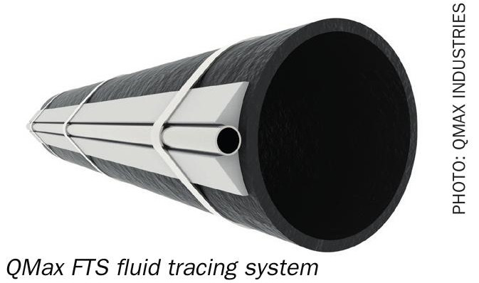
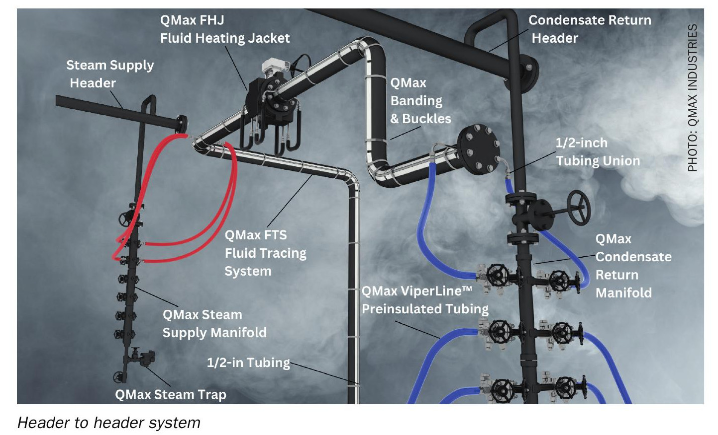
Conductive, bolt-on systems such as QMax’s Fluid Tracing System (FTS) address this issue by pairing bare tubing with an extruded aluminium channel. The channel acts as a thermal bridge between the heating medium (steam or hot oil) and the pipe wall, improving heat distribution and reducing the gap between heating-medium temperature and the sulphur’s bulk temperature.
A heat-transfer compound at the tube, channel and pipe interfaces is also essential. Although less conductive than metal, it is substantially more conductive than air. The objective is to achieve the thinnest reliable layer, typically around 0.015 inches (0.381 mm). Excess compound increases thermal resistance, making installation quality as important as the equipment selection.
Engineering determines tracer requirements
Tracer sizing is not a simple look-up exercise. Two pipes of the same diameter may require different tracer configurations depending on:
- pipe and insulation specifications;
- heating-medium temperature and pressure;
- process-fluid properties;
- ambient conditions;
- target operating temperature; and
- line geometry and heat-loss profile.
A proper thermal analysis should precede system selection. Without it, sections of a system may operate outside the required temperature range until an upset exposes the weakness.
This principle applies even to large installations. For example, a documented triple-train sulphur tail-gas tracing installation on 28-inch piping, operating at 262°F and 51 psig, used a bolt-on approach because thermal performance and installation flexibility, not pipe diameter alone, drove the design.
Tank heating requires the same discipline
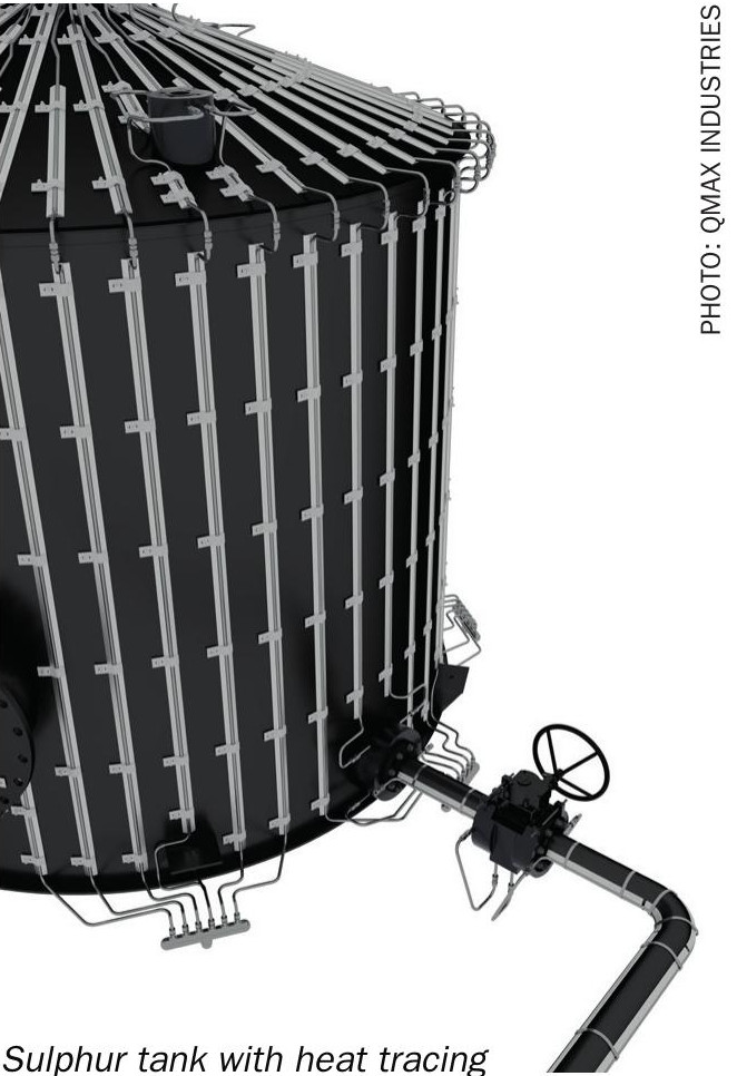
Molten sulphur storage tanks and pits present similar risks in a different geometry. Internal finned-coil banks, external bolt-on tracing and plate-coil systems can all be appropriate, provided the design delivers calculated, distributed heat rather than isolated hot spots.
The relationship between tank fill level, diameter and heat input is particularly important. A poorly designed system may first show its shortcomings as an underheated area (cold spot) near the tank floor, rather than through an obvious alarm or operating failure.
Tank-heating designs should therefore be supported by installation-specific thermal data rather than generic assumptions.
Vapour spaces create a separate failure mode
Sulphur vapour spaces behave differently from liquid sulphur systems. A liquid-line problem is usually visible: flow slows, pumps strain or level readings stop changing. In contrast, a vapour space that cools below its dew point may allow sulphur vapour and entrained mist to condense quietly onto cold surfaces.
This is especially hazardous in vent and relief lines. A blocked liquid line interrupts flow and is likely to be noticed. A vent line blocked by condensed sulphur can remain undetected while removing a critical pressure-relief path.
As long as the tank remains warm, sulphur may continue to off-gas H2S and sulphur dioxide. A plugged vent does not create the hazard; it removes a safeguard against it. Since these lines can extend for hundreds of feet, maintaining sufficient and uniform heat transfer throughout their length is a key engineering challenge.
Ignition risks in sulphur vapour spaces
Vapour spaces in sulphur storage equipment can present both toxicity and flammability hazards. Hydrogen sulphide–air mixtures can become flammable at relatively low concentrations, so combustible gas monitoring, inerting and sweep air dilution may be required to maintain safe conditions.
These areas can also develop pyrophoric iron sulphide scale. This material forms when sulphur vapours react with steel over time and may ignite spontaneously when exposed to oxygen, for example, during tank entry, inspection or after a blocked vent clears.
This risk affects how heating equipment is specified. Equipment in these zones should be appropriate for hazardous locations, with surface temperatures controlled by design.
On the liquid side, the central requirement is to provide enough heat to maintain sulphur in a molten state. In vapour spaces, the requirement is to maintain surfaces above the vapour dew point, limiting condensation, corrosion and potential ignition sites.
The bottom line
Sulphur’s narrow thermal operating range, and the serious consequences of operating outside it, mean that heat tracing must be treated as an engineered safety system. Effective designs require:
- heat-transfer calculations to support tracer selection;
- technology that delivers even heat distribution;
- documented, high-quality installation practices;
- tank and vapour-space designs that account for H2S accumulation and condensation risks.
QMax’s bolt-on FTS and its internal and external tank-heating solutions can each support this design approach. However, the critical factor is not the product alone, but whether the underlying engineering has been completed thoroughly. In sulphur service, that engineering provides the safety margin.