Sulphur 425 Jul-Aug 2026
Retrofitting with next-generation liquid sulphur treating


SULPHUR DEGASSING

Retrofitting with next-generation liquid sulphur treating

Retrofitting liquid sulphur treating into existing sulphur recovery units can significantly improve safety by reducing hydrogen sulphide in sulphur storage and handling, while also lowering the risk of toxic exposure and explosions. Worley Comprimo reviews proven treating technologies and retrofit options that can be implemented with minimal disruption to existing operations.


Over the past 35 years, an increasing number of companies worldwide have implemented liquid sulphur degassing processes in their sulphur recovery units (SRUs) to reduce the risks associated with hydrogen sulphide (H2S) release from produced elemental sulphur. H2S evolved from liquid sulphur can create an explosion hazard in sulphur pits and storage tanks when its concentration in the vapour space reaches a critical level. Of equal concern are the potentially fatal hazards of H2S exposure during sulphur loading and transportation.

Despite several serious safety incidents involving sulphur tanks and pits in the United States in the past, liquid sulphur treating is not mandatory. This contrasts sharply with Canada and Europe, where regulations and guidelines define maximum allowable H2S concentrations in liquid sulphur. These regulations typically apply to liquid sulphur during transport by rail, tanker truck, or ship.

Over the past decade, safety has received increasing attention across the hydrocarbon processing industry. For operators that do not yet have liquid sulphur treating capabilities, retrofitting this technology is a positive step toward improved safety stewardship. Liquid sulphur is among the most frequently transported hazardous materials in North America, and there is a growing expectation that most SRUs in the United States will eventually need to be retrofitted with liquid sulphur treating. This should not be viewed as an insurmountable challenge: the technologies required for safe handling and transportation of liquid sulphur are already available and have a well-established track record in the industry.

Removing H2S from elemental sulphur

SRUs convert H2S from various sources into liquid sulphur. They are found in natural gas plants, refineries, coal gasification facilities, and chemical plants. The sulphur produced by an SRU is chemically pure and is used mainly for sulphuric acid production.

Research has shown that H2S in liquid sulphur exists both as dissolved H2S and as H2Sx, a series of polysulphide compounds1. As sulphur condenses in the SRU, H2S dissolves into the liquid sulphur while complex chemistry also forms H2Sx. These chemical mechanisms depend on both system temperature and the partial pressure of H2S above the liquid sulphur. The presence of polysulphides has proven to be the limiting factor in successful elemental sulphur treating.

There are four main reasons for removing H2S from produced elemental sulphur2:

  • Lower the explosion hazard in sulphur storage and transportation.
  • Reduce the toxicity of liquid sulphur during handling and transportation.
  • Reduce the corrosive nature of liquid sulphur.
  • Reduce H2S emissions to atmosphere.
 

If dissolved H2S and polysulphides are not removed, high concentrations of H2S can accumulate in the vapour space above the liquid sulphur. If this vapour space is poorly ventilated, the risk of H2S explosion during storage and transportation increases significantly. The lower explosion limit (LEL) of H2S in air is well documented and typically ranges from 3.7% to 4.3%, depending on system temperature. Liquid sulphur is commonly transported by rail, road tanker, and dedicated marine vessels.

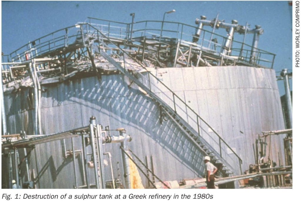
A number of incidents have been recorded, including the disappearance of the liquid sulphur carrier Marine Sulphur Queen and an explosion in a liquid sulphur tank at a Greek refinery in the 1980s that completely destroyed the tank. After that incident, liquid sulphur treating (degassing) prior to handling, storage, and transportation became mandatory in Europe. Fig. 1 shows the damage resulting from this explosion.

A similar tank explosion occurred in Texas in August 20083. In August 2016, a liquid sulphur storage tank was ruptured by an explosion at a refinery in California4. The resulting fire caused a sulphur dioxide release that required nearby residents to shelter in place to limit exposure. This incident vividly illustrates the ongoing risk that still exists in many refineries and gas plants in the United States, where a large portion of facilities continue to store undegassed sulphur in pits and tanks.

Tests have shown that treating liquid sulphur to below a threshold of 10 ppmw H2S prevents the formation of explosive mixtures in the vapour space above the sulphur. Even at this level, precautions remain necessary, as lethal concentrations of H2S may still be present in the vapour space. Industry literature includes numerous examples in which H2S released from elemental sulphur has resulted in fatalities.

The risks associated with the storage, loading, transportation, and unloading of liquid sulphur were described as the “forgotten hazard” at the 9th Global Conference on Process Safety in 20135. During handling and loading of untreated sulphur in particular, personnel can be exposed to high H2S concentrations and potentially explosive mixtures may occur. The National Institute for Occupational Safety and Health (NIOSH) specifies an immediately dangerous to life or health (IDLH) concentration for hydrogen sulphide of 100 ppmv.

Available treating methods

Several methods are available for lowering the H2S concentration in liquid sulphur. The most commonly used technologies employ air sparging through the liquid sulphur to convert H2Sx into H2S and elemental sulphur, while removing H2S from the liquid sulphur. Solid catalyst technologies are also available, as are liquid catalyst additions to promote H2Sx conversion and H2S removal. In some cases, these techniques are combined to meet the required specification.

Retrofitting liquid sulphur treating into existing sulphur rundown systems

There are several ways to implement liquid sulphur treating in an existing facility, depending on installed equipment, condition, and available infrastructure. When evaluating retrofit options, the following considerations should be taken into account:

  • minimal interruption to plant operations;
  • minimised implementation cost;
  • safety in all phases of engineering from design to installation, and final operation.

The following configurations may be considered:

  • installation of a new above-grade pressurised Shell/Comprimo sulphur degassing vessel;
  • installation of a new above-grade ICON™ sulphur degassing vessel;
  • retrofit of the existing sulphur pit or vessel with High Efficiency (HE) degassing.

Principles of air-based sulphur treating technologies

Sulphur produced in an SRU typically contains approximately 300–400 ppmw H2S. The H2S is partly dissolved in the liquid sulphur as free H2S and largely present as H2Sx formed during condensation in the sulphur condensers. The principle of sulphur treating is to accelerate polysulphide decomposition by injecting air into the liquid sulphur through spargers. This partially strips dissolved H2S from the liquid sulphur and partially oxidises it to elemental sulphur according to the following reactions:

Using any air based sulphur treating technology, the intimate air contact with the sulphur results in a treated product containing less than 10 ppmwt H2S/H2Sx.

It is worth noting that, as described in the paper by P.D. Clark and R.A. Marriott6 , the chemistry of liquid sulphur treating may be more complex than the simplified mechanism above. Laboratory analysis indicates that H2Sx also reacts with oxygen to form SO2 and H2S.


Shell/Comprimo sulphur degassing process

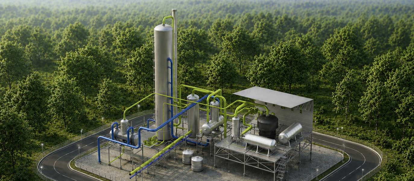
The Shell/Comprimo sulphur degassing process can be installed in a sulphur pit or in a vessel located either in a concrete sump or above grade, external to the sulphur pit. The description below refers specifically to Shell/Comprimo degassing technology installed in a new vessel downstream of an existing sulphur pit or rundown vessel, as shown in Fig. 2.

Installing a separate vessel simplifies the revamp by avoiding process and mechanical-integrity issues commonly associated with existing pits. The bubble columns required for this technology are difficult to retrofit into an existing sulphur pit. In addition, Worley Comprimo believes that sulphur degassing in a vessel offers important advantages in safety, reliability, and in the ability to route vent gas to the SRU thermal reactor.

Liquid sulphur from the SRU is pumped from the existing sulphur pit to the degassing vessel. If the sulphur temperature in the pit exceeds 300°F (149°C), the sulphur is cooled to below 300°F before entering the vessel.

The stripping air to the spargers is typically supplied by a dedicated blower, although other sources such as plant air may also be used. The air agitates the sulphur and promotes circulation in and around the bubble columns. This agitation enhances stripping of dissolved H2S and increases oxygen mass transfer into the sulphur, thereby oxidising most of the H2S and H2Sx to sulphur. In addition, removal of H2S from the sulphur promotes polysulphide decomposition. The resulting sulphur contains less than 10 ppmw H2S.

It is important to note that a chemical reaction between H2Sx and oxygen can also produce some SO2 and H2O6. Experimental data show that the oxygen in air is critical in sulphur degassing when catalysts are not used, since treating efficiency decreases dramatically when nitrogen or other inert gases replace air.

The treated sulphur flows from the degassing compartment to the storage compartment of the vessel, over an internal weir. Sulphur pumps then transfer the degassed sulphur to external storage, either continuously or in batch mode.

The total air fed to the degassing vessel, together with the H2S released from the liquid sulphur, is routed either to the thermal oxidiser or recycled back to the front end of the SRU, depending on local emissions requirements. Recycling the H2S-laden air to the front end of the SRU requires a pressure increase to overcome the pressure drop across the SRU. Two typical approaches are used to achieve the required pressure:

  • Pressurise the degassing vessel using utility air or compressed air at a minimum pressure of 20 psig (1.4 barg); this also improves mass transfer, reduces residence time, and reduces vessel size.
  • Use an ejector with a higher-pressure motive fluid, such as medium-pressure steam, to provide sufficient head for recycle.

The main impacts of a steam ejector are a slight reduction in SRU processing capacity due to steam load and a slight reduction in thermal reactor temperature. These effects are usually modest, but they should be evaluated on a case-by-case basis. There is no impact on sulphur recovery efficiency.

ICON process

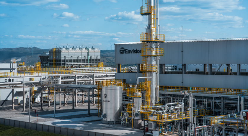
The CSI/Ametek ICON degassing system uses a solid catalyst and a sparge gas to remove hydrogen sulphide from liquid sulphur. In the example shown in Fig. 3, the liquid sulphur is first routed to a cooler to ensure that the temperature is below 302°F (150°C). From the cooler, the sulphur flows to the degassing contactor, which contains the degassing catalyst.

The ICON™ process converts H2Sx in the liquid sulphur to H2S, and a sparging gas is used to remove the H2S that is now in solution. No air is required for this conversion, so the technology is not based on air sparging; however, very low H2S concentrations in the liquid sulphur can still be achieved. The treated sulphur contains less than 10 ppmw H2S.

The sulphur is pumped from the degassing vessel to storage facilities, where it is either loaded into trucks, railcars, or barges, or sent to solidification facilities. Because oxygen is not required to convert H2Sx, the sparge gas in ICON technology can be steam or nitrogen. This allows vent gases to be returned to the process, whereas air-based sulphur degassing technologies always require vent gas treatment either in the thermal reactor, for very low emission targets, or in the thermal oxidiser.

High-efficiency sulphur degassing

The newest sulphur degassing technology available to the industry is based on intensely mixing air with untreated liquid sulphur, either through a pump or an inline sparger. This technology was installed and tested at a facility in the United States. The plant had a total design sulphur production of 30 t/d, and by intensely mixing air with sulphur pumped from the pit, a final sulphur product quality of 12 ppmw H2S was achieved. This was sufficient to prevent explosive mixtures in the vapour space of the sulphur pit and thereby improved the overall safety of plant operation.

A general process flow scheme for the Worley Comprimo high efficiency (HE) degassing technology is shown in Fig. 4.

The purpose of this installation was to remove limitations caused by H2S releases at a nearby rail sulphur loading station. Before installation, the area had to be cordoned off and air-breathing masks were required during loading. After the HE degassing technology was installed, sulphur loading could be carried out without these precautions.


Installing HE degassing in an existing sulphur collection pit can be done at substantially lower cost than other technologies; however, due to the limitations of a recycled system, it does not yet reduce H2S as low as the other technologies described. Depending on sulphur pump capacity and sulphur plant production, H2S concentration can typically be reduced to 10–30 ppmw. This is generally sufficient to eliminate explosion risks associated with H2S in the vapour space of a sulphur pit. Alternative configurations are still being explored to create a once-through system with potential to achieve the same target of below 10 ppmw H2S.

Modifications to sulphur storage and handling

Once sulphur treating has been installed in the SRUs, the produced sulphur routed to tanks and loading stations will contain less than 10 ppmw H2S. This may or may not affect the venting requirements of existing sulphur tanks.

When storing untreated sulphur, sufficient sweep air should be maintained in the tank to keep the H2S concentration in the vapour space below 1%, equivalent to less than 25% of the LEL for H2S. This is typically achieved by installing multiple heated air intakes at the edge of the tank roof and a heated central vent stack, sometimes equipped with ejectors. Through natural or induced draft, a continuous sweep is maintained through the tank. Sweep-air rates depend on the air temperature in the vapour space of the tank, elevation difference between intakes and the vent stack, and hydraulic losses across the nozzles. Tank design must also consider sulphur pump-in and pump-out conditions, as well as ambient effects on available natural draft.

When an existing sulphur tank is converted from undegassed to degassed sulphur operation, the presence of a natural-draft system may increase SO2 formation in the vapour space, potentially leading to additional emissions. It is Worley Comprimo’s standard practice to design treated sulphur storage tanks with venting systems that minimise sweep. This is achieved by installing three properly heated vent stacks at equal spacing and the same elevation on the roof of the tank, without a central vent stack. This allows the small quantity of H2S released from degassed sulphur to react with oxygen in the vapour space, while minimising SO2 formation, which typically occurs with continuous airflow across the sulphur surface.

If local regulations do not permit any H2S or SO2 emissions from the sulphur tank, an induced-draft sweep-air system may be required. This would involve air- or steam-driven ejectors to direct sweep air either to the thermal oxidiser or to the SRU thermal reactor.

If it is necessary to alternate between storing treated and untreated sulphur in the same tanks, a system can be designed that allows the operator to open or close the central vent stack and operate the tank either as a naturally swept system or as a vented system. However, such changing operating modes introduce inherent risk. When revamping an existing tank, calculations should be performed for all expected conditions to verify that sweep-air rates are sufficient to keep H2S below 25% of the LEL. Tank vapour-space temperature is critical in this assessment, and thermal models such as those described by Hornbaker et al.8 may be required to predict it. In addition, computational fluid dynamics (CFD) modelling may be needed to verify that the existing sweep-air system can eliminate pockets of elevated H2S concentration in the vapour space.

Summary

Storage, loading and unloading, and transportation of liquid sulphur remain a “forgotten hazard” in the sulphur industry in the United States. During handling and loading of untreated sulphur in particular, personnel can be exposed to high H2S concentrations, and potentially explosive mixtures can form in the vapour space of storage vessels.

Sulphur treating technology greatly reduces the risks associated with untreated liquid sulphur. This article has presented several options available to the industry for retrofitting liquid sulphur treating technology with minimal impact on existing operations. These options can be adapted to local environmental regulations and plant-specific infrastructure, resulting in safer and more reliable SRU operation. There is no longer any reason to accept the risks of explosions or hazardous exposure during the handling and transportation of liquid sulphur.

References

Latest in Emissions