Nitrogen+Syngas 401 May-Jun 2026
27 May 2026

Conversion of biomass to chemicals and synthetic fuels
BIOMASS GASIFICATION
Conversion of biomass to chemicals and synthetic fuels
Uhde’s PRENFLO gasification technology provides a proven core building block for the conversion of biomass into chemicals and synthetic fuels. Continuously developed and adapted to evolving requirements, the technology can play a significant role in enabling the clean and sustainable production of syngas and syngas-derived products from an even broader range of carbonaceous feedstocks than ever before.
While sourcing of green hydrogen is globally making its way via water electrolysis, green carbon can only be sourced from biogenic origin. Leveraging a globally commercialised track record in coal gasification technology, and based on more than 100 gasifiers successfully realised by thyssenkrupp Uhde, PRENFLO pressurised entrained-flow gasification is now available for lignocellulosic biomass feedstocks. It produces clean syngas at very high efficiencies, which can then be used to produce clean fuels such as methanol and SAF for the maritime and aviation sectors, or clean fertilizers.
Milestones in Uhde’s gasification history
It all began in 1924, when Uhde secured its first major contract: the construction of a wood gasification plant in what was then Czechoslovakia. This milestone marked a pioneering entry into the chemical conversion and utilisation of solid hydrocarbons, and the beginning of a journey that has led to today’s use of biomass as a green carbon carrier for the climate-neutral production of chemical products.
Coal beneficiation
Demand for coal beneficiation technologies surged, prompting Uhde to advance its coal liquefaction technology toward commercial maturity. This led to the engineering of a large-scale coal liquefaction plant based on the Uhde process, followed by a contract for a plant designed to produce gasoline from brown coal (lignite). In parallel, Heinrich Koppers and his employee Friedrich Totzek developed the patented entrained-flow gasifier, later known as the Koppers-Totzek gasifier. The technology was ultimately built 77 times worldwide and used in the production of ammonia, methanol, hydrogen, and fuels. Compared with established coal gasification technologies at the time, it offered higher efficiency and significantly reduced byproduct formation.
Oil later emerged as a major growth area. Uhde was one of only three companies worldwide to receive an engineering license from Texaco for the global commercialisation of its oil gasification technology. This partnership laid the groundwork for the construction of numerous Texaco oil gasification plants in the decades that followed.
Oil crisis and coal chemistry
The first oil crisis triggered a renewed focus on coal. With many energy experts at the time expecting oil and gas reserves to be depleted within a few decades, technologies for the clean utilisation of coal and biomass experienced a resurgence. Uhde and Koppers responded to the crisis with decades of expertise in coal chemistry: the first Texaco coal gasification plant and the first Shell-Koppers coal gasification plant both came on stream. Uhde’s coal liquefaction experience also came to the fore, culminating in a cooperation agreement with Mobil Oil Corporation to build the world’s first methanol-to-gasoline (MTG) plant for Union Rheinische Braunkohlen Kraftstoff AG in Wesseling, Germany. Today, MTG technology is once again gaining importance in the production of e-fuels: in combination with green hydrogen and CO2 from industrial off-gases, it enables the production of green gasoline from methanol through Carbon2Chem®.
World record: Integrated gasification combined cycle (IGCC)
Building on experience gained through contracts for a peat gasification plant for ammonia production in Finland and a brown coal gasification plant for methanol production in Berrenrath, Germany, Uhde entered the integrated gasification combined-cycle (IGCC) power sector with the KoBra project. The concept was to use coal gasification to fuel a combined-cycle gas and steam turbine power plant, reducing CO2 emissions by 30% compared with conventional coal-fired power plants. In 1998, the world’s largest single-train solid-fuel IGCC plant was commissioned for Elcogas in Puertollano, Spain to generate 320 MW of electricity using a gasifier that converts hard coal, refinery residues, and biomass into power (Fig. 1).

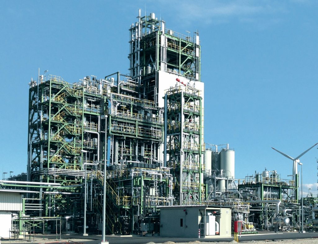
In 2020, PRENFLO entrained-flow gasification was operated exclusively on biomass for the first time in the BioTfueL project in Dunkirk, France (Fig. 2). BioTfueL supports the climate-neutral production of aviation fuel (kerosene) from biomass, bringing the company’s 100-year development journey full circle – from its origins in Czechoslovakia to the present day. More recently, PRENFLO has also experienced a resurgence in clean coal gasification projects in India and North America.

Uhde’s experience in gasification
As a technology-driven company, Uhde draws on extensive experience in the development, design, and construction of oil and coal conversion plants. This expertise spans more than 100 years and has been continuously refined to the present day. To date, Uhde has designed and built more than 100 gasifiers worldwide, based on eight different gasification technologies, including the Koppers-Totzek process, the Shell-Koppers process, the Shell gasification process, the Texaco process, the High-Temperature Winkler process, and the PRENFLO process, covering all feedstock types: solid, liquid, and gaseous.
These technologies also encompass upstream and downstream process steps such as heat recovery, gas treatment, including sulphur recovery, wastewater treatment, and subsequent conversion routes for the production of sustainable aviation fuel, methanol, ammonia, hydrogen, oxo-chemicals, and electrical power. Taken together, this body of expertise positions Uhde as a world-leading engineering group in gasification technologies and downstream applications.
Gasification
Gasification is the partial combustion of carbonaceous feedstocks in the presence of a moderator, such as steam or carbon dioxide (CO2), to produce raw syngas.
2(CH2) + O2 → 2CO + 2H2
In contrast to complete combustion, gasification takes place in a reducing atmosphere. It can be carried out using a broad range of feedstocks, including gaseous streams such as refinery gases, natural gas, or LPG; liquid feeds such as various oil fractions, heavy residues, or orimulsions; and solid feeds such as coal, petroleum coke, biomass, or even waste products.
Over the past century, a range of gasification technologies has been developed, progressing from early laboratory testing to full commercial deployment. Today, several state-of-the-art technologies are available and have been fully proven at commercial scale.
In general, three commercially available gasification technologies can be distinguished (see Table 1):
- fixed-bed gasification;
- fluidised-bed gasification;
- entrained-flow gasification.

The most efficient option is the entrained-flow gasification process, as it converts nearly all the carbon in the feedstock and produces no undesirable by-products such as methane, tars, or heavy aromatics. It is also operationally flexible, allowing the use of a wide range of feedstocks, including nearly all types of biomass and coal. The raw syngas produced is of consistent quality regardless of the feedstock used and contains very little CO2.
By contrast, fixed-bed and fluidised-bed gasification technologies are more limited in their feedstock flexibility and generate undesirable by-products such as methane, aromatics, and tars. These reduce process efficiency and require additional, cost-intensive treatment for removal.
Uhde’s state-of-the-art PRENFLO gasification technology
The gasification of solid fuels exhibits significant variability in operating conditions, primarily with respect to gasification temperature. This temperature range is governed by ash properties, which can be controlled by adjusting the ash chemistry through the addition of fluxing material, typically limestone or silica sand, to the raw feedstock. During operation, the fluxing material can be varied to determine the optimum dosage for a given feedstock.
Accordingly, the plant control system is based on the carbon mass flow to the gasification burner, calculated from feedstock analysis data and mass flow measurements in the dust feed lines to the burners. The oxygen-to-carbon ratio is then regulated to ensure gasifier operation under optimised conditions.
The advantages of the PRENFLO concept (Table 2), with its slagging membrane wall design, have been demonstrated at commercial scale for more than 17 years, for example in the Elcogas IGCC plant in Puertollano, Spain. This facility is the world’s largest single-train, solid fuel-based integrated gasification combined-cycle power plant, operating with more than 100 t/h of coal/petcoke mixture as feedstock. During operation, Elcogas also tested the addition of up to 10% biomass to the feedstock blend.

To demonstrate the suitability of the proven PRENFLO gasification technology for operation with 100% biomass, the BioTfueL® project was launched in 2010 by Bionext, a consortium comprising six major industrial partners: Avril, Axens, CEA, IFPEN, Uhde, and TotalEnergies. The project was designed and implemented to convert lignocellulosic biomass, including straw, forest residues, and dedicated energy crops, into high-quality advanced biofuels such as renewable diesel, SAF (sustainable aviation fuel), and naphtha via an indirect thermochemical pathway, while minimising environmental impact. Tests conducted at the large-scale demonstration plant in Dunkirk, France, under representative operating conditions exceeded expectations.
General process description
The PRENFLO gasification with direct quench (PDQ) process is an advanced solid-fuel /multi-fuel gasification technology, based on a simplified design of the proven PRENFLO gasification with steam generation (PSG) process, which has been successfully installed at Elcogas in Puertollano, Spain.
A simplified process flow diagram of PRENFLO gasification with direct quench is shown in Fig. 3.

First, the feed dust is prepared in the feed preparation unit and sent to the feed dust bunker (1). Approximately 80% of the dust must have a particle size below 0.1 mm. The feed dust is then pressurised in a lock hopper system (2) and stored in the feed bin (3). From there, it is conveyed to the gasifier by dense-phase conveying using a conveying gas.
The feed dust is gasified in the PREN-FLO gasifier (4) with oxygen and steam/ CO2 as gasification agents. The gasification temperature is above the ash melting temperature, allowing the feedstock ash to be removed as slag (6 + 7). The cooled-type gasifier, which produces medium-pressure steam in a steam drum (8), is equipped with multiple horizontally arranged burners. The raw gas produced, consisting mainly of carbon monoxide and hydrogen, is quenched with water in the gasifier direct quench (5) and then cleaned in a scrubber (10). The filter cake from the slurry filtration system (9) is largely recycled to the gasifier via the feed preparation unit. The slag from the gasifier can be used as a construction material. Typical operating parameters of a PRENFLO gasification unit are summarised in Table 3. The plant consists of the following main units:
Gasification unit
To address the limited service life of refractory linings, as used in most fixed-bed and fluidised-bed technologies, as well as the associated downtime, the PRENFLO process employs a cooled membrane wall as the reaction chamber within the gasifier vessel. Multiple opposing burners are integrated into the cooled membrane wall (see Fig. 3), which operates at a sufficiently high temperature to ensure that the feedstock ash is converted into molten slag. The slag flows downward by gravity and is removed from the bottom of the gasifier.
Feed dust, as well as any liquid or gaseous feedstocks, enters the PRENFLO gasifier through the burners. The feedstock is then partially oxidised with oxygen supplied from an air separation unit (ASU) or an electrolyser unit.
After leaving the burner mouth, the particles are heated with sharp temperature gradients. The volatile constituents are released spontaneously and together with carbon are oxidized by free oxygen as follows:
After exiting the burner mouth, the particles are rapidly heated under steep temperature gradients. The volatile components are released spontaneously and, together with the carbon, are oxidised by free oxygen as follows:
C + ½O2 → CO
CO + ½O2 → CO2
H2 + ½O2 → H2 O
The temperature generated by these reactions, together with the progressive depletion of free oxygen, promotes the following endothermic reactions, which proceed substantially more slowly than the corresponding heterogeneous oxidation processes:
C + H2O → CO + H2
C + CO2 → 2CO
The interaction of gas components containing hydrogen and carbon is controlled by the slightly exothermic, homogeneous water-gas shift reaction:
CO + H2O → CO2 + H2
The formation of methane according to the reaction:
CO + 3H2 → CH4 + H2O
is suppressed due to high temperature at the burner and in the gasifier.
The inherent ash in the feedstock flows down the cooled gasifier wall as molten slag and passes through the quench zone into the slag pool, from which it is discharged via the slag removal unit.
The generated raw gas and entrained fly ash also move downward and exit the reaction chamber through the bottom opening into the first quench zone. There, the raw gas is quenched, further cooled, and saturated by water spray nozzles supplied with condensate and recycled process water.
At the bottom of the first quench zone, the raw gas is redirected upward through an annular space – the second quench zone – formed by the pressure vessel on the outside and the first quench zone on the inside.
Scrubbed fly ash from the raw gas is collected in the slag collecting ves-
sel and in the surrounding water bath. Excess water is pumped by the quench water circulation pump to some of the quench nozzles. In addition, a continuous water stream is withdrawn to prevent the accumulation of solids.
Slag removal unit
The granulated slag is discharged from the slag collecting vessel inside the gasifier water bath via the slag cooling section, slag crusher (if any) and slag distributor to the slag lock hopper(s).
A slag extractor is installed beneath the slag lock hopper to receive the slag during emptying of the hopper. Coarse material is removed from the slag extractor, while the remaining water, containing fines, is pumped to the slag fines removal unit.
Slag fines removal unit
To maintain the particle load in the gasifier-quench system and slag removal unit below a defined threshold, a bleed stream is continuously withdrawn from the gasifier. A second stream is discharged from the slag extractor to the slag fines removal unit. There, these slurry streams are depressurized, degassed, and cooled. The treated slurry is then sent to the water pretreatment unit.
Scrubbing and sour condensate system
The raw syngas produced in the gasifier is routed to the scrubbing system, which primarily consists of the venturi scrubber and the downstream scrubber. In this system, the remaining fly ash particles, as well as undesired trace components such as HCl, are removed from the syngas. As a result, a very clean syngas is delivered at the battery limit of the PRENFLO gasification unit to the downstream synthesis gas cleaning unit.
Water pre-treatment
A flocculant is added to the flashed slurry from the slag fines removal unit before it is fed to the clarifier. In the clarifier, the flashed slurry is separated into a solids-rich stream and a clear overflow water stream.
PRENFLO gasification standard sizes and capacities
The PRENFLO gasification technology is suitable for single stream thermal heat input of 15 MW (demonstration unit scale) up to 1,200 MW (large industrial scale). For applications with 100% biomass, typical gasifier capacities are designed up to 600-700 MW thermal input (Table 3).

Various applications and process chains
The PRENFLO gasification technology serves as a core building block in a range of process chains for converting carbonaceous feedstocks into high-value intermediate and final products, such as chemicals and synthetic fuels, primarily methanol for the maritime sector and sustainable aviation fuel.
The upstream units are designed to prepare the feedstock for pneumatic feeding into the PRENFLO gasifier. They typically include a conventional grinding unit. For biomass applications, drying, torrefaction, and, where required, pelletisation are considered upstream of the grinding unit to produce a feedstock suitable for comminution. A similar approach is required for the use of various waste-derived feedstocks, such as municipal solid waste.
The downstream units ensure that the raw gas leaving the gasifier is shifted and converted through multiple process stages into clean syngas that meets the specifications of the product units.
Fig. 4 illustrates the various application areas of gasification-based plants across the same industrial sectors that are traditionally supplied with natural gas and oil as feedstocks. One key application of gasification-derived synthesis gas is ammonia production.

Ammonia is widely regarded as a promising future carbon-free energy carrier because it does not emit carbon dioxide at the point of use. In addition to green ammonia, produced via water electrolysis, and blue ammonia, produced from natural gas with carbon capture, ammonia production from coal or biomass gasification represents an attractive alternative, particularly given the wide availability and competitive cost of these feedstocks.
The raw gas leaving the gasifier must undergo shift conversion, removal of feedstock-derived impurities such as sulphur compounds, and separation of carbon dioxide. For this purpose, well-established scrubbing technologies commonly used in gas-based ammonia plants can be applied. In a manner similar to certain natural-gas-based blue ammonia configurations, nitrogen is supplied via an air separation unit (ASU). A key synergy of gasification is that such an ASU is already integrated into the process, while the nitrogen stream remains unused. As a result, typical gasifier capacities can support ammonia production rates of approximately 2,000 to 3,000 t/d, corresponding to a technically proven and well-established plant scale.
Gasification inherently converts a high amount of carbon. In ammonia production, where carbon does not form part of the final product, it is ultimately released as CO2. A major advantage of gasification, however, is that this CO2 is generated as a concentrated stream, which can be routed directly to sequestration without the need for energy-intensive separation from dilute flue gases.
Gasification-based ammonia is also well suited to conventional fertilizer applications. When urea is the final downstream product, the available CO2 is sufficient to convert the full ammonia output into urea. Alternatively, the ammonia can be used in the production of nitrate-based fertilizers.
Overall, these examples show how gasification, by using a low-cost feedstock, can reduce dependence on natural gas and its associated price volatility while also avoiding the challenges linked to the intermittent availability of renewable energy. With its inherent readiness for CO2 sequestration, gasification represents a future-proof technology for the production of low-carbon hydrogen and ammonia.
If the downstream process requires a syngas composed of H2 and CO, the syngas output can be significantly increased by integrating an electrolysis plant. In this configuration, the hydrogen and oxygen streams produced by electrolysis eliminate the need for both the CO shift downstream of gasification and the air separation unit.
Summary and outlook
The PRENFLO technology has a decades-long track record and has been continuously developed and adapted to evolving requirements. Initially designed for the chemical utilisation of coal, it was later extended to include petroleum coke from refineries as well as biomass fractions. As the use of coal for power generation through combustion became increasingly unacceptable in many parts of
Europe over the past decade, and chemical utilization was not actively promoted, biomass emerged as a promising carbon-rich and sustainable feedstock for the future. PRENFLO was subsequently adapted for operation with 100% biomass and successfully implemented and tested at the BioTfueL plant in Dunkirk, France.
To date, PRENFLO is regarded as a robust, proven, and flexible state-of-the-art technology that has consistently delivered strong results and has more recently become the technology of choice for numerous customers worldwide in the conversion of second-generation biomass.
In October 2025, following the Indian government’s program to significantly expand the use of domestic coal for the development of a coal chemistry industry, PRENFLO was selected for a project to produce syngas as an upstream unit for a DRI iron production facility in Telwasa, Taluka Bhadravati, Chandrapur, Maharashtra State, India.
Today, gasification once again has the potential to play a significant role in the clean and sustainable production of syngas and syngas-derived products, using an even broader range of carbonaceous feedstocks than ever before, from biomass to clean coal solutions and beyond.