Sulphur 424 May-Jun 2026
Analysis of a Claus catalytic reactor unit


SIMULATION AND MODELLING

Analysis of a Claus catalytic reactor unit

Claus process catalytic reactors are a key component of sulphur recovery units. Under normal operating conditions, the catalyst bed inlet temperature is a process set-point such that a desired reaction conversion is achieved. However, depending on the design, operating, and external environment conditions significant heat losses may result in reduced efficiency, requiring increased heat duty of reheaters, or even result in operational and reliability risks due to potentially corrosive cold zones. Simulation-based analysis using a multiphase multiphysics model was used to predict these effects for an industrial-scale Claus catalytic reactor.*

Catalytic reactor units (CRUs) are a key component of sulphur recovery units (SRUs) based on the Claus process and, where applicable, hydrogenation tail gas reactions. CRUs involve process gas being fed through an insulated packed bed reactor with a supported catalyst which promotes the exothermic Claus process-related reactions,where n = 2, 6, and 8. While reheating incurs significant operating costs, CRUs and condensers pose operational challenges.

2H2S + SO2 = Sn + 2H2O

Typical hydrodynamic conditions in industrial scale CRUs result in turbulent flow both within inlet/outlet void spaces and within a central multilayer supported catalyst bed (porous media). The catalyst bed inlet temperature is a process set-point such that, under normal operating conditions, a desired reaction conversion is achieved. However, depending on the design and operating conditions (normal, turn-down, co-firing, etc.) significant heat losses and temperature variations within the catalytic bed may occur. Additionally, hydrodynamic conditions resulting from particular reactor designs (Fig. 1) are known to increase risk for catalyst displacement. These variations might result in reduced sulphur recovery efficiency, requiring increased heat duty of reheaters, or even result in operational and reliability risks due to potentially corrosive cold zones.

Typical Claus process CRUs have three different internal regions: inlet, catalyst bed, and outlet. The inlet region is single-phase (process gas) where, ideally, there is simple unidirectional diverging flow from single or multiple inlets to the catalyst bed. The catalyst bed region is multiphase (process gas, porous solid) in which there are upper and lower layers of inert particles to protect and support a central (interior) layer of catalyst particles. The outlet region is single-phase (process gas) where, ideally, there is simple converging flow from the catalyst bed to single or multiple outlets.

The number and geometry of reactor inlets along with the catalyst bed layer thickness and particle sizes are key design decisions which affect the cost, catalytic performance, pressure drop, and reliability of CRUs. Current trends in the operation of SRUs motivate increasingly long intervals between shutdowns which necessitate increasingly reliable reactor designs. Poor designs and/or deviation from expected operating/ambient conditions can result in cold spots that potentially can lead to corrosive regions within the reactor.

Relatively little publicly-available work has been performed to analyse CRUs using simulation-based methods, which enable access to time-evolving three-dimensional details of their internal operation. In this work, simulation-based analysis using existing multiphase hydrodynamic, thermal, and reaction kinetics models, coupled together and referred to as a multiphase multiphysics model, is performed for a representative industrial-scale CRU. The basis for this work is an applied research study in which simulations were performed for a CRU for which limited industrial process data exists1 , enabling some degree of simulation validation. Additionally, recent past work2 focused on formulation of the multiphase model and simulation-based analysis of different inlet configurations and their effect on internal multiphase hydrodynamics.

In this work, a simulation study of the CRU design presented in ref. 1 was performed under standard operating and environmental conditions to assess the effects of heat transfer from the CRU to the external environment on its internal thermal characteristics. The simulation was performed for a fully three-dimensional CRU geometry (Fig. 2), using a combination of hydrodynamic models of compressible turbulent flow (Favre-averaged Navier-Stokes model, FANS) and inertia-dominated flow in porous media (Darcy-Forchheimer model).

Porous media transport properties were estimated using a typical catalyst loading scheme used in most CRUs combined with semi-empirically determined correlations of inertia-dominated flow in porous media3 for uniform diameter (simple, monodisperse) randomly-packed spheres (catalyst particles). The Claus reaction kinetics model1 used was based on a simplification of an original kinetic model presented in ref. 4. Analysis of simulation-predicted process gas flow distribution, temperature variation, and component composition were performed for both single-phase inlet/ outlet regions and the porous catalyst bed region under normal operating conditions shown in Table 1. External environment conditions were considered with an ambient temperature of 25°C (77°F) and a relatively high rate of wind-driven convection (50 kph).

Modelling and simulation methods

The modelling and simulation methods used in this work involved decomposing the CRU into three coupled sub-domains and appropriate models for each: inlet, catalyst bed, and outlet. Consequently, standard interior boundary conditions are introduced coupling transport of mass, momentum, and energy which are not included for brevity. Additionally, radiative heat transfer is neglected and not expected to significantly affect results based on a scaling analysis using the Stefan-Boltzmann law and the two characteristic temperatures associated with normal operating conditions (inlet and catalyst bed temperature).

Single-phase compressible turbulent flow in the inlet and outlet regions was modelled using the compressible FANS model, which uses density-weighted time averaging versus classical time averaging used for incompressible turbulent flows (Reynolds-averaged Navier-Stokes mode, RANS). Additional approximations and submodels used for the inlet and outlet region model include:

  • perfect gas equation of state (ideal gas with constant heat capacity);
  • JANAF empirical relations for thermodynamic properties (heat capacity); Sutherland law for dynamic viscosity;
  • mass-fraction weighted mixing to the thermodynamic coefficients;
  • Wilke equation-based mixing for transport properties;
  • k−ε turbulence model.

Fluid flow through the catalyst bed region was modelled as coarse-grained porous media using the Darcy-Forchheimer model with the Ergun equation5, which relates local pressure gradient and fluid velocity,

where A/B are dimensionless constants, µ is the dynamic viscosity, ρ is the density of the fluid phase, d is mean particle diameter, and ε is the porosity of the porous medium. The dimensionless constants A and B vary depending on the fluid flow regime within the porous medium. For CRUs, including the unit studied in this work, fluid flow within the porous catalyst bed is well-within the turbulent flow regime with a particle Reynolds number Rep >> 2000. This simplifies flow parameters in that they become constant with respect to fluid velocity based on past experimental research3.

Interphase heat transfer in the catalyst bed was modelled without the standard assumption of local thermal equilibrium (LTE) and, instead, using a more detailed local thermal non-equilibrium (LTNE) model captured using an effective heat transfer coefficient between the fluid (process gas) and solid (catalyst particle) phases5-6,

where T and Ts are the temperatures of the fluid and solid phases, respectively, and the heat transfer coefficient hsf and specific surface area between phases asf are,

where dp is the particle diameter, λf is the thermal conductivity of the fluid phase, and the Nusselt number Nu which has been estimated in past research for high Rep7.

An open-source implementation of the FANS and Darcy-Forchheimer models with supporting closures is used as provided by the OpenFOAM simulation software package (version 11)8, which enables external verification of the presented results through the use of an open-access simulation software.

CRU configuration and operating conditions

This simulation study is based on a CRU design and operating conditions from past work of Zughbi and Razzak1, which provides both real-world operating data and reference multiphysics simulations of a multi-inlet CRU with dimensions shown in Fig. 2.

Normal operating conditions, based on real-world data, involve an inlet mass flowrate of approximately 50 kg/s (110 lb/s) which corresponds to an inlet superficial velocity of 57 m/s (187 ft/s) for a three-inlet configuration. Experimentally measured inlet and outlet temperatures and component mass fractions are shown in Table 1. Based on recent past work using simulations to study the effect of multiple inlets and the use of inlet flow deflectors, the CRU geometry used in this work differs from past work in that inlet flow deflectors are added in order to reduce the predicted surface stress on the catalyst bed by several orders of magnitude compared to conditions without inlet flow deflectors2.

Past work indicated1 that the catalyst bed was composed of 1.4 m (4’ 7”) of 3 mm (1/8”) diameter spherical catalyst particles, however, this would potentially have mechanical stable issues and it is assumed that inert support layers were neglected to reduce computational complexity. In this work, simulations are performed assuming a catalyst bed configuration representative of real-world conditions with top/bottom inert support layers and the catalyst layer (as-specified in previous work) but with 3/16” spherical catalyst particles. From top to bottom, the catalyst bed layer configuration used is:

  • upper support layer 0.08m (3”) of 1/2” inert support
  • catalyst layer 0.97m (38”) of 3/16” catalyst
  • lower support layer 0.15m (6”) of 1/2” inert support

The Claus catalytic reactions were modelled using non-elementary power-law rate expressions with the reaction rate constants approximated using the Arrhenius equation as presented in Zughbi and Razzak1,

where Ri is the rate of reaction, A is the Arrhenius constant, R is the gas constant, E is activation energy, T is temperature, β is a dimensionless exponent, and f([i]) is the rate law expression. The reaction rate expressions used in ref. 1 were based computationally-motivated simplifications of empirically-determined rates expressions9 for the three reversible reactions representing the formation of different sulphur allotropes (S2 , S6 and S8 ),

where E = 3.06×10⁴ J in units (kmol/s m). It is noted that S2 formation is expected only at higher temperatures than present in CRUs, but the reaction is included in past and current simulations for completeness.

Heat transfer conditions within the catalyst bed were approximated as described in the previous section. External convective heat transfer conditions were modelled using an environmental temperature of 25°C (77°F) with a wind speed of 50 kph (h= 40 W/m2 K). The bottom portion of the CRU was assumed to have 2 inches gunned castable up to 6 inches above the top of the catalyst hold down layer. External insulation was assumed to be 4 inches of mineral wool over the entire exterior of the unit.

Computational multiphysics analysis

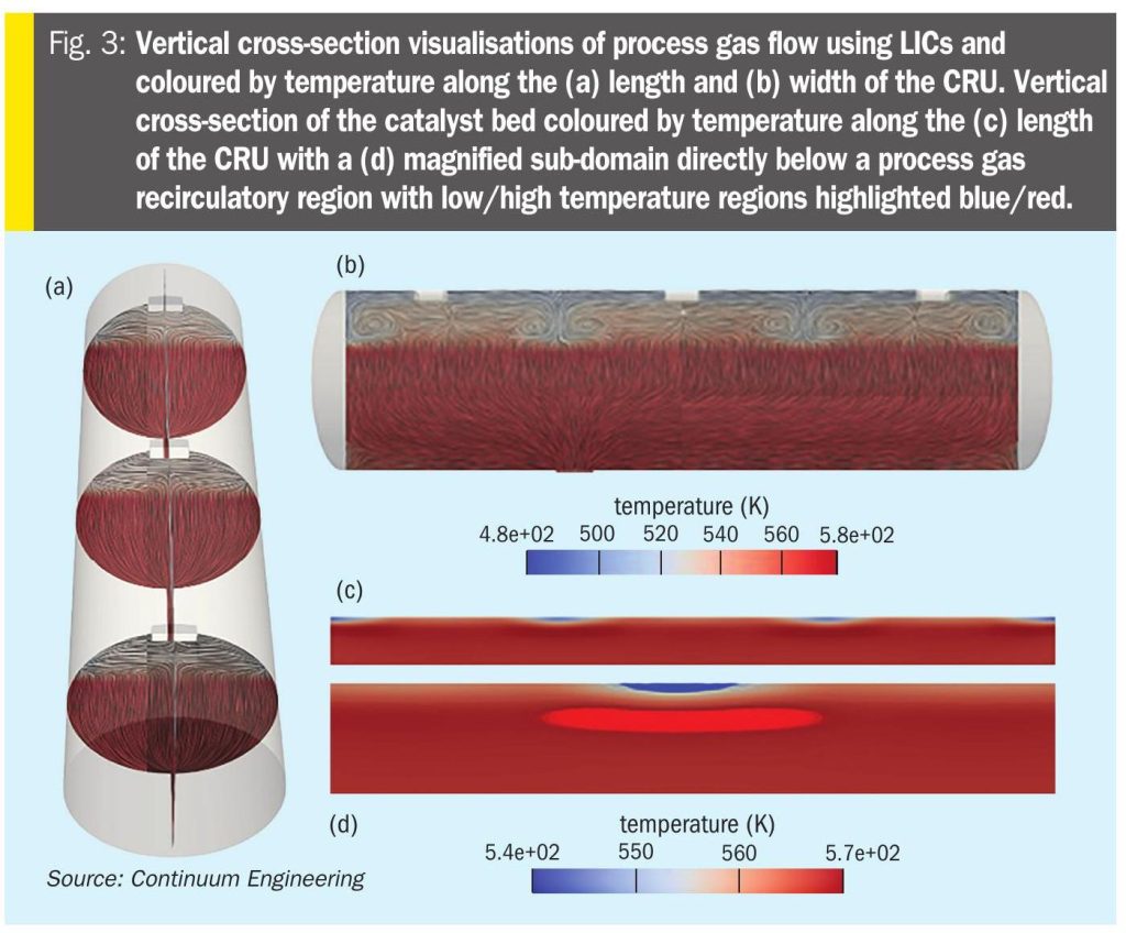
Transient multiphase multiphysics simulations were performed starting with the CRU at a uniform temperature of 572 K, the observed outlet temperature from process measurements. The simulation was continued until the mass fluxed-averaged outlet temperature remained constant over a period of 10 s of simulation time. Simulation visualisations of developed flow and temperature profiles within the CRU under standard operating conditions are shown in Figs. 3a-b, which use the line integral convolution (LIC) method10 to visualise the flow orientation on different internal cross-sections. Inlet flow is equally divided between each of the three inlets, then further divided axially by each of the three impingement plates. This results in redirection from axial to downwards flow both at the ends of the reactor and in between pairs of inlets.

The overall flow topology involves the presence of multiple recirculatory regions above the catalyst bed. The catalyst bed then imposes quasi-ideal distribution of the inlet flow due to the highly dispersive property the solid porous phase. The outlet region is predicted to have an almost ideal converging flow from the catalyst bed to the single outlet, which is intuitive given the almost ideal distribution of flow entering the outlet region. Past studies showed that there are an equivalent number of recirculatory regions imposed above the catalyst bed without and with inlet impingement plates. However, the use of inlet impingement plates reduces hydrodynamic stresses on the surface of the catalyst bed by an order-of-magnitude2.

Referring to Figs. 3c-d, which show vertical cross-sections through the centre of the catalyst bed and are coloured by catalyst particle temperature. There is a direct correlation to the presence of inlet recirculatory regions above the catalyst bed, shown in Figs. 3a-b, and temperature variation within the bed. Horizontal changes in catalyst bed temperature are directly related to the recirculation region pattern above the bed. In the vicinity of these recirculation regions, there are significant vertical changes of temperature within the upper region of the catalyst bed. These temperature variations are complex, as is shown in the magnified region shown in Fig. 3, with low temperature (< 556 K) and high temperature (< 574 K) regions directly below each of the recirculation regions. The low temperature region is exposed to recirculatory flow composed of inlet process gas within the inert (non-reacting) portion of the catalyst bed. This explains why these regions are local minima in temperature. However, directly below these regions of low temperature are corresponding regions of high temperature, with an approximate change of temperature of 10 K, which can be better understood through analysis of reactant/product compositions, in that the high temperature region is below the inert support particles and within the catalyst particle region.

To better understand the cause of temperature variation within the catalyst bed, Figs. 4a-b show vertical cross-sections of H2S and Sx mass fraction within the process gas flowing through the catalyst bed. The presence of simultaneous heat transfer to/from the process gas and heat generation from exothermic chemical reactions results in several key simulation-based observations:

  • Recirculation regions above the catalyst bed result in mixing and transport of partially reacted process gas from the catalyst bed back into the inlet region, reducing the mean inlet mass fraction of reactants flowing into the catalyst bed.
  • Regions of the catalyst bed in between recirculation regions and along the vessel walls exhibit a lower temperature due to the majority of lower temperature inlet process gas being directed to these regions.
  • Regions of the catalyst bed directly below the interface between recirculation regions transition from local temperature minima to local temperature maxima due to higher reaction rates resulting from the combination of slightly (i) elevated reactant concentration and (ii) lower velocity/higher residence time.

These observations are further supported by iso-surfaces visualisations of low/high values of the Sx fraction within recirculatory regions shown in Figs. 4c-d. Recirculation is found to convect some of the product Sx from the catalyst bed against the net flow direction into the inlet region.

While the consequences of complex recirculation flow above the catalyst are extremely complex, they are clearly detrimental to performance and utilisation of the full volume of the catalyst bed. Furthermore, as can be seen from the almost ideal converging flow in the outlet region (Fig. 3b), reduction/removal of inlet recirculation is both most compatible with the dispersive properties of the porous phase of the bed and would result in improved performance of the CRU overall, with respect to reaction conversion and heat transfer.

Overall, simulations of the industrial scale CRU performed in this work with the addition of inlet flow deflection plates is predicted to improve overall conversion, with the predicted outlet flow properties shown in Table 1. Furthermore, outlet process gas temperature was predicted to be closer to that measured from the industrial process, through the incorporation of more realistic heat transfer mechanisms compared to past simulations.

Conclusions

Multiphase multiphysics simulation-based analysis was performed for an industrial scale Claus reactor unit (CRU) and was found to show reasonable agreement with industrial process measurements and predict an improved performance resulting from the inclusion of inlet flow deflection plates. Several multiphase and multiphysics phenomena were found to make important contributions to the overall performance of the CRU including: interphase heat transfer between the process gas and the catalyst bed, process gas transport within the layered porous bed, and inclusion of heat transfer with the environment through the CRU shell.

The porous solid catalyst bed phase was found to be relatively uniform in temperature close to that of the outlet process gas, with slight deviations in temperature above recirculatory zones in the inlet region. The combination of the inert upper support and catalyst particles were found to act, in addition to a catalyst for the Claus reaction, as an ideal flow distribution layer. Additionally, the improved inlet distribution of the process gas resulting from the use of inlet flow deflection plates was predicted to result in a slight increase in reaction conversion, compared to operation of the CRU without these inlet features.

Simulation-based analysis of catalytic reactors present in Claus processes is a promising predictive tool for assessment of performance of existing units and their design. Innovations in catalytic reactor design, including inlet flow distribution, have the potential to result in increased extended catalytic reactor performance and reliability under all relevant operating conditions, while simultaneously reducing operating costs associated with high reheater duty and/or premature SRU shutdown due to poor catalytic performance.

*The authors of this article are T. Treeratanaphitak of Sirindhorn International Institute of Technology, Thammasat University Pathum Thani, Thailand; E. Nasato of Nasato Consulting Ltd. Oakville, Ontario, Canada; N.M. Abukhdeir of Dept. of Chemical Engineering University of Waterloo, Ontario, Canada and Continuum Engineering Inc., Waterloo, Ontario, Canada.

References

Latest in Equipment