Sulphur 421 Nov-Dec 2025
24 November 2025
Sulphur pit turnaround and rehabilitation
A full sulphur pit turnaround and rehabilitation is typically a once in a lifetime experience for refinery personnel. Specialists in sulphur pit turnarounds, Gavin Palmer of Brindley Engineering, Tom Kline and Bob Hall of Structural Technologies have compiled a database based on multiple sulphur pit turnarounds to identify typical deficiencies in mechanical systems, along with improvements to enhance operability, restore functionality and meet all codes/standards and best practices.
How many refinery facilities can say they have the luxury of prior experience when entering a sulphur pit for turnaround? Often, these concrete vaults in the ground are overlooked as truly being a piece of refinery process equipment, often being run until the last feasible point of failure and limped into turnaround. Hence, it can be upwards of 15 to 20 years between full pit turnaround and rehabilitation, with personnel having prior experience of pit entry having been promoted, reassigned to other roles/units, or even having left the company. The current team may not even know who was involved during prior work.
Brindley Engineering, in partnership with Structural Technologies, has been involved in upwards of 30 sulphur pit turnarounds in the past seven to eight years alone. During this time a database of common deficiencies has been compiled to assist in execution of future pit turnarounds, whether it be due to poor initial design or installation, changes in codes/standards/best practices, operational changes etc.
Sulphur pits strive to maintain an elevated temperature range for their molten sulphur contents via steam coils that provide heat and, hence, fluidity to the molten sulphur. This must be accomplished without significant temperature fluctuations which can hamper process flow within the sulphur train. Perimeter backfill soils surrounding the buried pit provide consistent temperature profiles if groundwater, condensate or steam coil malfunctions are controlled and maintained in accordance with OEM guidelines.
Typically, the “last straw” before bringing a pit down for turnaround and rehabilitation tends to be the interior condition of the pit; be it concrete damage, ground water intrusion, steam coil failure or roof panel condition. In this instance, all mechanical systems (e.g. jacketed sulphur rundown lines, sulphur seals, steam and condensate piping, instrumentation, eductor inlet lines, air vents, pumps and associated sulphur transfer piping etc.) are typically removed back to the first flanged connection outside of the pit to facilitate roof removal and access. Many sulphur pits also have manway access hatches/explosion hatches which are included in the pit roof system. Hence, this is a time when improvements to these systems can be evaluated and often implemented with minimal incremental cost to the project.
Whilst the majority of sulphur pits are unique, in this article, typical deficiencies in mechanical systems are identified, along with improvements to enhance operability, restore functionality and meet all codes/standards and best practices. Knowing the potential for these deficiencies in time to engineer a solution can aid in the timely execution of the overall rehabilitation work within evertightening turnaround windows, returning the pit to reliable service on time.
Concrete liner and effect on pit volume/capacity
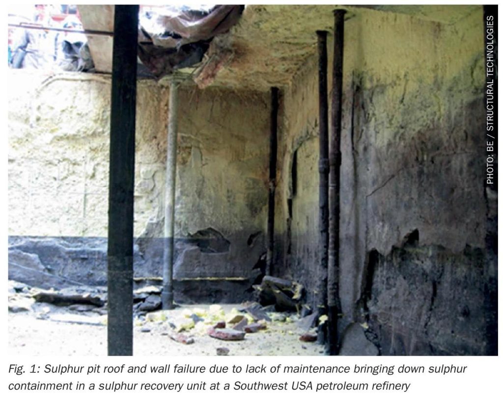
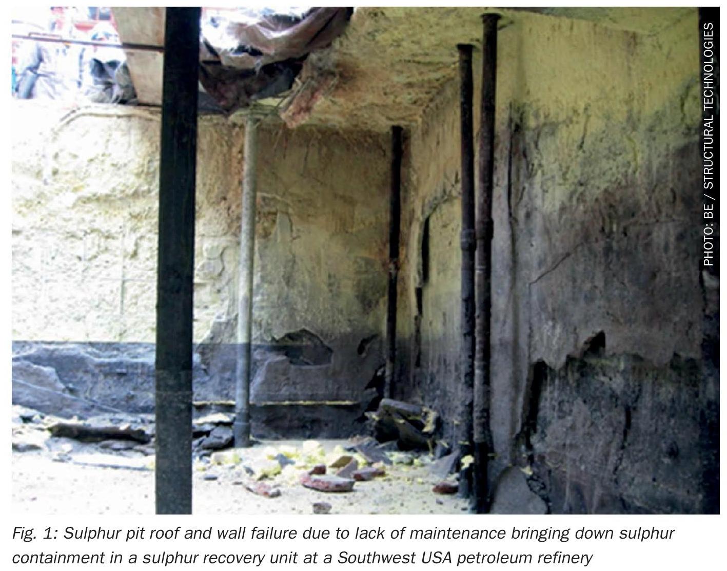
The primary reason for pit rehabilitation is the need to repair deterioration in the concrete structure, often by way of a concrete liner (a 4-inch durability liner or a thicker, up to 20-inch, structural liner). Ground water intrusion, steam leaks, rainwater entry etc. can all introduce water into the pit, which, in combination with the molten sulphur, results in a complex corrosion mechanism that spalls the interior concrete surfaces over time, particularly the walls and roof panels. Not generally thought of as a revenue generating asset, the failure of civil/structural components associated with the support or containment of process operations can quickly limit processing capacity, perhaps even reducing overall unit throughput – costing precious revenue until repairs are made and the process is brought back online (see Fig. 1).
Given the nature of sulphur flow, rundown lines from the back end of the reaction furnace waste heat boiler and its downstream sulphur condensers must slope towards the pit and be installed with no pocketing of the piping runs. Hence, the sulphur pit is often located immediately adjacent to, and sometimes tightly within the bounds of, the overall sulphur unit footprint. Access is limited, and further hindered by all the mechanical systems serving the pit – piping, pumps, instruments, electrical feeds, pipe supports and racks etc.
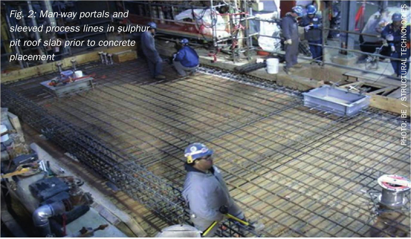
These services must be pulled back to the edge of the pit to access the pit for structural repairs to the walls and new roof panels (either pre-cast or cast-in-place) to be installed (see Fig. 2).
Residence time for degassing
Sulphur rundown to the pit can contain up to 400 ppm of dissolved and entrained H2S gas, which must be evolved into the vapour space and removed (see air sweep section below). However, the rate at which this H2S can be “degassed” from the molten sulphur is mass transfer driven, and empirical data suggests that this can take in the region of 2 to 4 hours. With the thickness of the new concrete liner being taken into account, an analysis should be carried out to ensure that existing residence times are not adversely affected. In some instances, it can be determined that the pit did not offer adequate residence time as originally designed and improvements can be made. These can include relocating inlet lines to increase their distance from the pumps/sump area (easier when external sulphur seals combine to a single inlet line), modifying the civil design to include partition walls and create/extend “degassing” sections within the pit or installation of a simple baffle wall to lengthen internal flow paths. The goal should be to maintain or increase the residence time to acceptable values, particularly for cases where the molten sulphur is loaded to trucks/railcars for immediate delivery to off-site customers.
Storage capacity reduction
Similarly, a reduction in pit volume must be evaluated from a logistical standpoint to ensure that truck/rail loading and/or transfer operations are not adversely affected.
Location of services (e.g. roof nozzles) due to thickness of concrete liner
Often, services such as steam inlets, condensate outlets, pump penetrations etc. are located around the edge of the pit and simple replacement-in-kind is not feasible due to the thickness of the new concrete liner. The design must be adjusted to incorporate the new dimensions and eliminate any potential clashes between the liner and the mechanical components of the pit.
Sulphur rundown piping to pit and sulphur seals
Option to replace conventional liquid seal legs
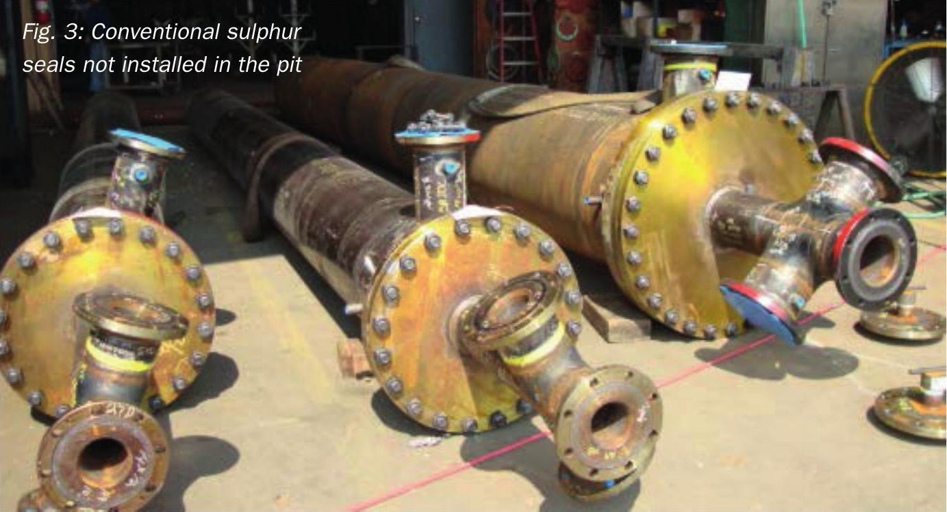
Many installations still utilise in-ground or in-pit liquid seals to ensure that H2S laden process gas at unit pressure does not breakthrough into the low pressure vapour space (typically a slight draft under atmospheric pressure) in the sulphur pit. These seals are essentially a liquid seal-leg, or p-trap type device constructed as a pipe within a pipe; given the length required (typically 16-18 ft or 0.78 psi/ft) to hold back unit pressure (see Figs 3 and 4). They are often housed in cylindrical vaults in the ground outside the pit, or directly inside the pit itself. Whilst they are a known and well-proven apparatus, they do have their drawbacks. A consistent unit pressure will maintain a liquid level in the seal and over time localised corrosion of the inner pipe can occur at the liquid-vapour interface, eventually breaching the pipe wall and allowing process gas to “burp” directly into the pit at pressure. This creates a safety concern with regards to pit overpressure, as well as incidental release of H2S-rich vapour to the environment through pit air inlets or look-box covers. Ground water intrusion can also corrode the outer pipe in some installations, resulting in process gases leaking directly to atmosphere at grade.

Liquid seal legs are cumbersome to remove from service for maintenance given their size and location, requiring a crane and vertical clearance considerations to remove and reinstall. Many facilities have upgraded these seals to a more compact mechanical float design (examples include CSI Ametek’s Sx Seal® or the SOS SulTrap™). These traps are installed above grade with a more compact overall design, requiring less clearance for installation and removal, and with adequate isolation can be maintained or repaired in place.
A pit revamp is the perfect opportunity to make this switch, especially given that existing in-pit seals may need to be relocated/redesigned anyway to accommodate any potential clashes with the concrete pit liner. These designs can also incorporate built-in sight glasses to verify liquid flow, eliminating the need for look boxes (see below). The design must consider the slight difference in level required between inlet and outlet piping for these devices, especially in situations where there is a limited elevation change between the sulphur rundown source (e.g. condenser outlet nozzle) and the entry into the pit.
Elimination of look boxes
Arguably the most hazardous portion of the sulphur pit, if not the entire unit, are older style look boxes; whether using a hinged lid (clipped or wired in the closed position) or a bolted cover, they are typically the source of most of the hazardous sulphur and H2S leaks seen at the pit. In some instances, pressure excursions in the pit, or even flow surges local to the seal (due to corrosion and potential breaching of the pipe wall inside a seal leg for example) have caused box lids to be blown open and molten sulphur to shoot tens of feet through the air, while also releasing H2S to the atmosphere. A pit outage is an ideal time to upgrade to a more secure look box (with built in sight glasses) or even to eliminate the look boxes completely and provide an inline “pour behind” type sight glass for flow verification. These devices avoid typical issues with fogging and discoloration of the sight glass by taking a small slipstream of the sulphur flow and pouring it a short distance behind the glass, providing a much finer level of flow verification by operations personnel.
Steam coil design
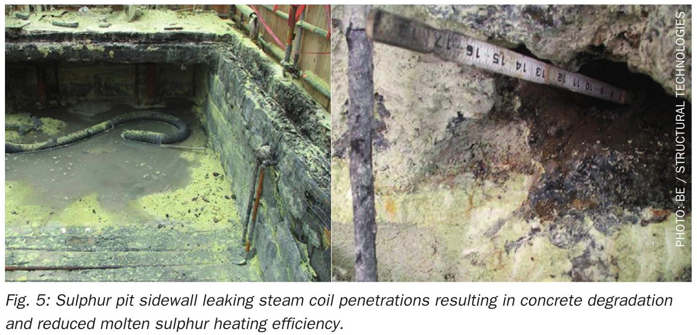
Likely secondary only to the physical condition of the concrete pit itself, the steam coil system on a sulphur pit is often in incredibly poor condition once the pit is available to be rehabilitated. Coils may be leaking steam and condensate into the pit, exacerbating damage mechanisms to the pit walls, while some may have been shut off and abandoned completely. Condensate trapping systems may be stalled due to poor condition, maintenance and/or initial design, with condensate (or worse, live steam) being directed to “safe” locations at grade to reduce backpressure on the coils. Leaks from steam coil assemblies can also have their own detrimental effects on the condition of the concrete walls, as shown in Fig. 5.
A dead giveaway to poor heating performance is putting steam into a coil and seeing some of that same steam venting from a cracked open strainer valve. Whilst the intention is typically good (one would think that some flow is better than no flow) steam must condense to provide the full benefit of its heating capability; any sensible heat is just a fraction of the available latent heat.
In this section, we’ll break down the ideal steam coil system design, and explain why attention to the details of steam/condensate movement are critical in this particular application:
Steam pressure
The sulphur temperature is not directly controlled by modulating steam flow through the coils; instead, the pressure is restricted to 60-65 psig to limit the heating potential of the steam. At temperatures of around 312°F, there is a marked viscosity increase in pure degassed liquid sulphur, making it near impossible to handle in sulphur pit applications – certainly for centrifugal type pumps. Hence, limiting saturated steam temperatures to 307°F (60 psig) eliminates any possibility of reaching this condition. Note that the pump vendor will have specific steam supply pressure requirements for the jacket of the sulphur pump which is typically 35 psig saturated steam; this pump steam pressure requirement is separate from the sulphur pit steam supply pressure. There is, however, a drawback – even 60 psig offers a limited driving force to maintain condensate movement out of the coils, particularly given that the low point of the system is below grade.
Optimal physical design of coils
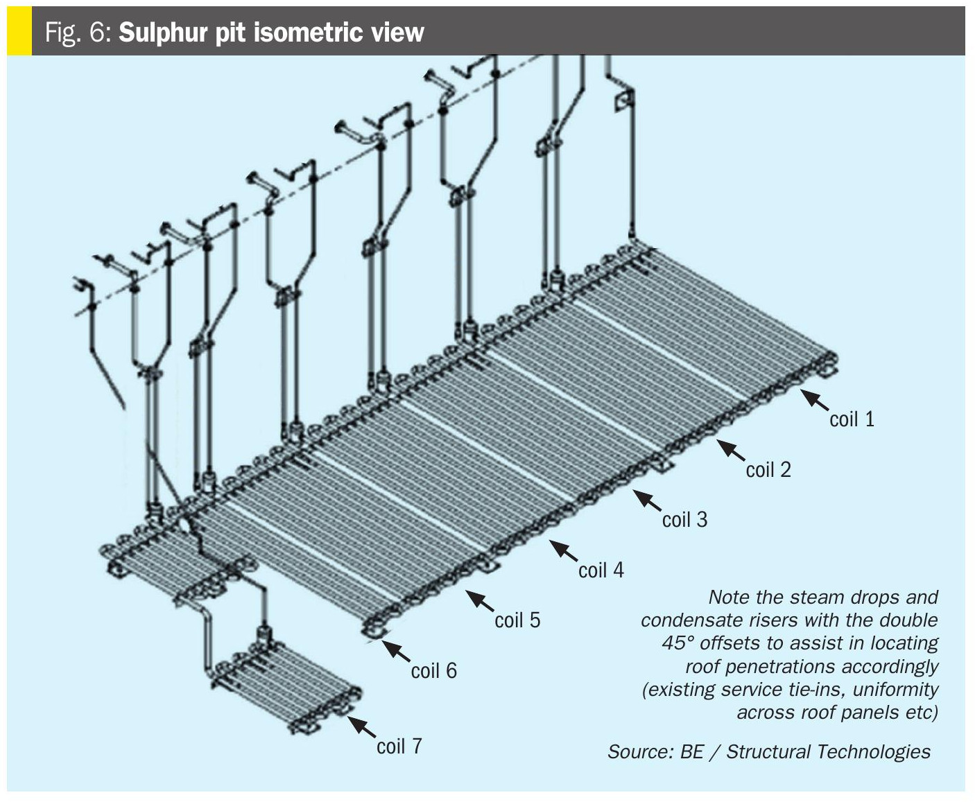
Empirically, a 2-inch diameter coil offers the best balance of surface area for heat transfer, steam velocity and 2-phase flow of steam and accumulated condensate – as well as being physically strong enough to withstand damage across a potentially 20-year service life. A smaller diameter coil results in a high pressure drop and stalling of condensate in the system, while larger diameter coils have a low surface area relative to their volume. Coils should be limited in length, typically 150 to 200 ft maximum per coil to avoid cold spots in the pit (a long coil will condense all steam prior to the end of the coil, and condensate has a negligible heating value relative to steam) – this is a similar concept to other critical steam applications such as process steam tracing for heat loss mitigation. Coil runs are typically limited to 8 to 12-inch on-centre spacing, often driven by the pipe fittings used to make the 180° bend but also close enough to avoid cold spots and provide uniform heating across the entire floor. Coils should be designed to run as close to the walls as is feasible, typically 4 to 8-inch based on overall pit geometry. Note here that the installation of a 4-inch durability liner or up to 20-inch structural concrete liner often drives a complete rework of the coil layout to begin with. Similar shape, coverage, geometry coil panels are often designed to cover the bulk of the pit for simplicity in engineering and fabrication. However, a small number of specialty coils may be required, particularly around pump suctions and other pit internals close to the floor (see Fig. 6 ).
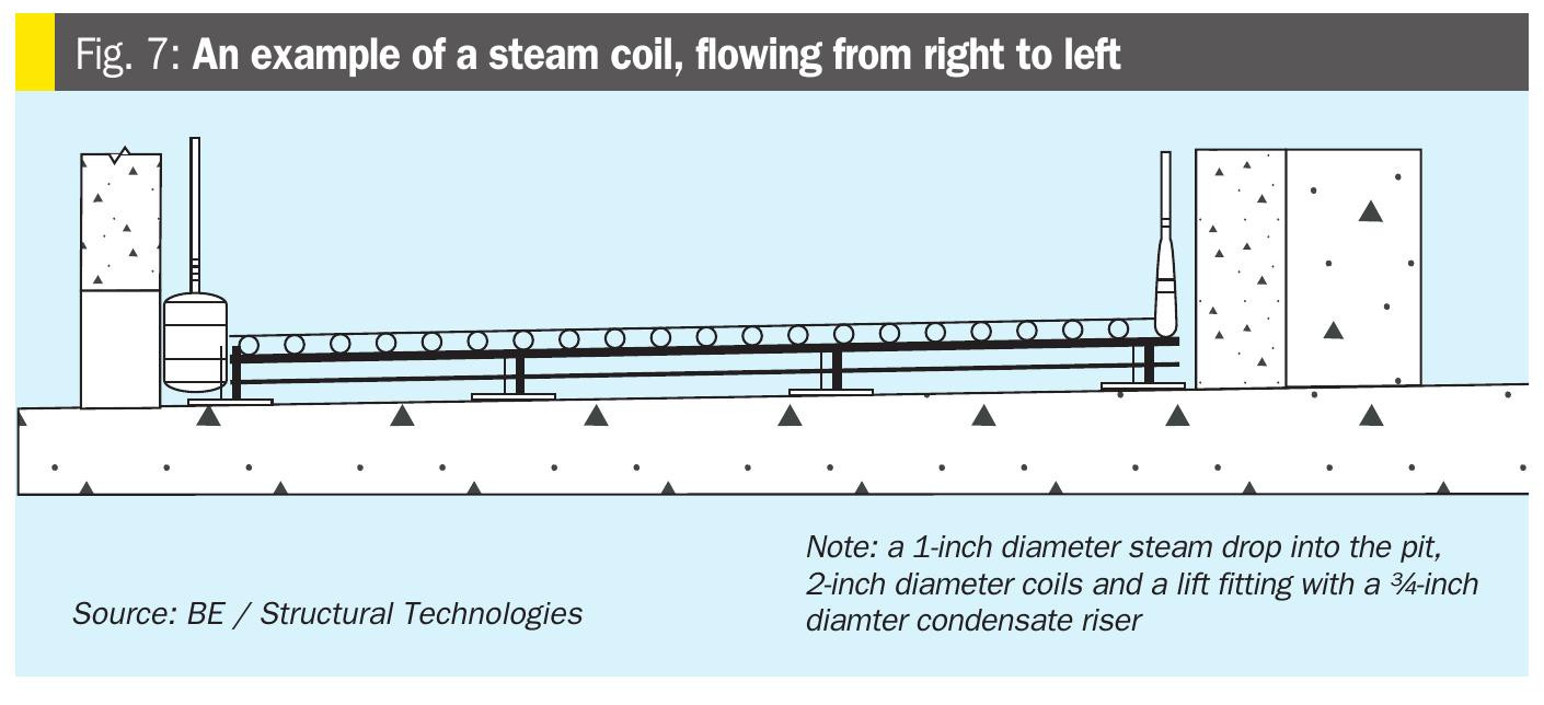
Steam drops
The steam drop (i.e. the vertical piping run from the top to the bottom of the pit) itself is not required to transfer heat to the molten sulphur, in fact it is preferred that it not. A 1-inch diameter line provides a slightly higher velocity and less residence time in the vertical drop to the coil to assist in this, whilst not adding much in appreciable pressure drop. It is also easier to route a 1-inch diameter line down the wall of the pit from entry point to coil, particularly if this is not a straight shot vertically down. In this case, 45° fittings should be used to offset the piping. The steam drop is often clipped to wall of the pit for support (Fig. 6).
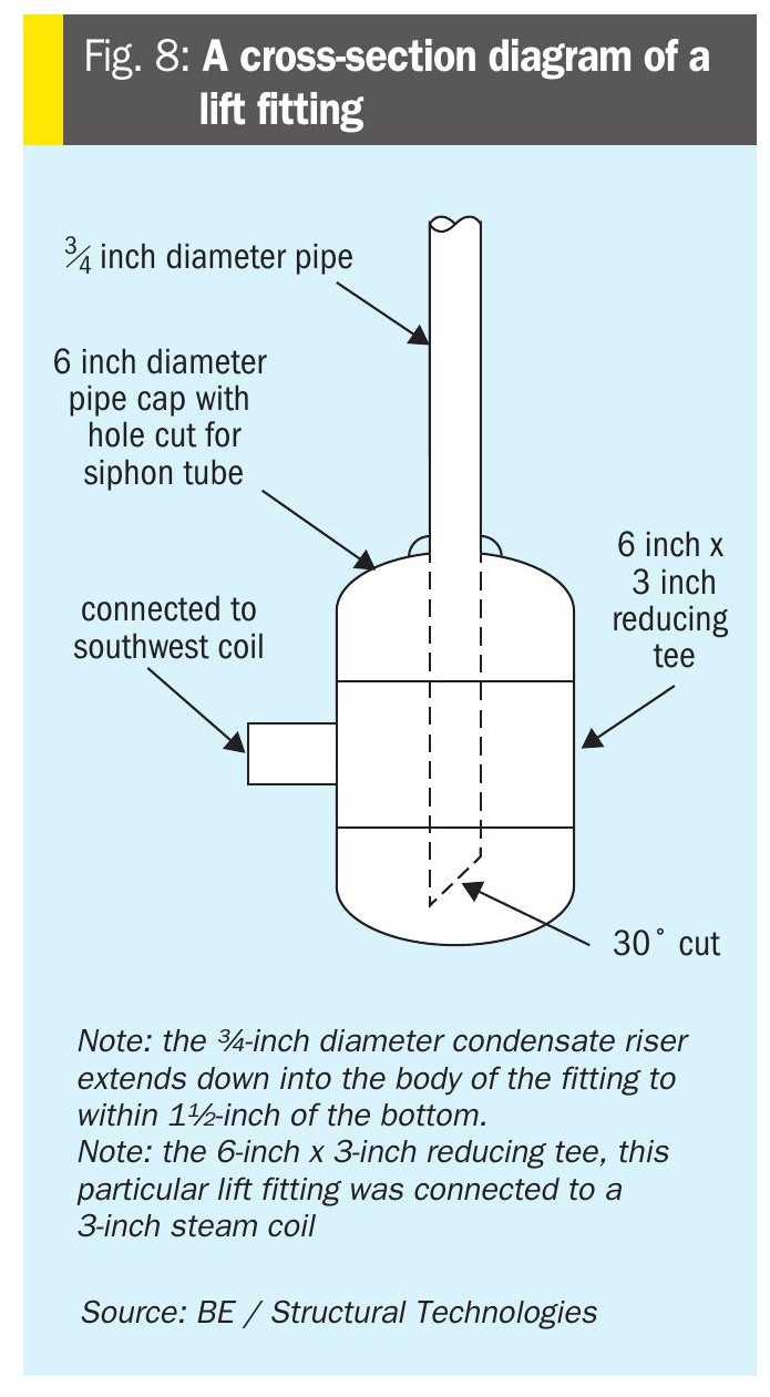
Lift fittings and siphon tubes (condensate risers)
Perhaps the most critical and unfortunately the most overlooked part of the steam coil system, a well-engineered lift fitting is key to efficient and consistent removal of condensate. Steam traps typically serve as the physical boundary between steam and condensate in heating applications such as this, however, they are always placed at the low point of the system, where gravity allows condensate to accumulate. This is not feasible in a below-grade concrete pit filled with molten sulphur. Hence, a lift fitting with no moving parts is used as a de-facto steam trap – the steam trap at grade, outside of the pit, is a back-up device should steam breakthrough occur in the lift fitting below.
There are a few designs that achieve this requirement, the most effective being a small vertical cylindrical chamber at the end of the steam coil, 4 to 6-inch in diameter. Condensate draining from the coil piping enters the lift fitting in the centre of the side wall and exits up a ¾-inch diameter siphon tube that extends down into the lift fitting (see Figs 7 and 8). Condensate will typically accumulate in the lift fitting above the siphon tube’s lower opening, ensuring that only condensate will be pushed up to the trap at grade. In fact, for steam breakthrough to occur, almost all the condensate would need to be evacuated, which is unlikely when correctly sized. A 4 to 6-inch diameter fitting provides adequate volume to prevent steam breakthrough due to any variation in rates of condensate formation. This also provides a relatively large area for residual steam pressure in the coil and upper portion of the lift fitting to act on the liquid surface, assisting in pushing condensate up the siphon tube to the steam trap.
Correct selection and optimised installation of steam traps
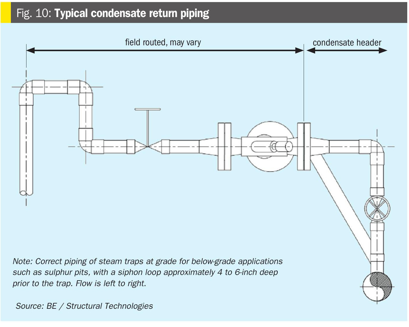
Even though the actual trap at the surface is a back-up to the lift fitting as discussed above, its selection is critical to steam coil performance and must not be overlooked. A well performing lift fitting will ensure that the steam trap only sees condensate most of the time and will remain open. It will only close if steam breaks through the lift fitting and travels up the siphon tube to the trap. Given that steam pressure is limited to ~60 psig by design (see above), a low pressure drop trap is critical here, as is a trap that maintains condensate movement regardless of temperature. An inverted bucket or floating ball trap (see Fig. 9) is ideal for this application and should be specified with a vent hole or other non-condensable vent capability for consistent operation. Note that thermostatic traps must not be used in this application, as they require a higher pressure drop for condensate to flow and require that condensate be subcooled by 15-20°F before opening. This action will fight the function of the lift fitting described above and back up subcooled condensate into the coils. One additional feature that can be employed in the piping installation around the trap is small siphon loop up, over and down prior to the trap (shown in Fig. 10). This is recommended in sub-surface condensate removal applications by many steam trap vendors to assist in reestablishing condensate flow after a steam breakthrough event. Finally, beware the steam trap vendor who comes into your facility and makes wholesale changes to trap technologies across the entire plant or unit. This is the number one reason for the incorrect type of trap being installed in sulphur pit steam coil applications.

Metallurgy selection
Older installations utilised carbon steel for many of the internal mechanical components in the pit, particularly below the expected minimum level of sulphur in the pit. Corrosion of carbon steel in an anaerobic wet H2S environment allows the formation of Iron sulphide, a pyrophoric material that can become an ignition source for fires or explosions within the pit vapour space – particularly during shutdown/decommissioning for turnaround/maintenance.
Iron sulphide can form in anaerobic pockets under deposits of solidified sulphur at cold spots within the pit; should the deposit later be released from its position somehow, this iron sulphide is exposed to air and will ignite spontaneously. There is also the ever-present risk of wet sulphur corrosion to carbon steel components in the vapour space, due to moisture in the sweep air. It is typically recommended to install only stainless steel (SS) components inside the pit, including all pipe nozzles, coil piping, clips and supports etc. It is often considered acceptable to transition to carbon steel (CS) below the normal low sulphur level within the pit, however, the dissimilar weld at the CS/SS transition is a known point of accelerated corrosion and leaks here can occur. Given the length of time between internal pit inspections and maintenance, it is generally recommended to push for all-stainless construction. Piping can be transitioned to carbon steel at the first available flange outside of the pit.
Air sweep – eductor(s) and air inlet(s)
Verification of eductor capacity, or maximum unit throughput at code limitations (35% of H2S LEL) – NFPA 655: Prevention of Sulphur Fires and Explosions, clearly states that, “5.2.3 Operations shall be discontinued whenever instruments show a combustible gas concentration of 35 percent or more of the lower explosive limit in the gas space of liquid containers” and that, “5.2.4 Operations shall not be resumed until the instruments indicate a concentration of 15 percent or less of the lower explosive limit”. Now, “discontinuing operations” in a refinery sulphur pit is not easy to define or even achieve, however, both are shall statements – yet very few installations have the ability to measure or even calculate H2S levels in the pit in real time. In many instances, design calculations for eductor sizing and expected H2S content of the incoming streams are also not available for reference, or may be outdated compared to current operating throughputs. At a minimum, it is recommended to install (a) flow measurement device(s) in either the air inlet(s) or the piping to the eductor and use this flow to calculate a predicted H2S content within the sulphur pit based on known H2S content of the sulphur inlet streams combined. A more robust approach is direct H2S measurement in either the pit vapour space or the inlet piping to the eductor. Packaged H2S measurement systems designed specifically for this application are available.
Simulation of H2S content in rundown streams (HYSYS Sulsim) – where existing heat and material balance (HMB) data does not contain detailed H2S content for the streams entering the pit, the required concentrations can be determined by simulation, either of the entire unit or just the condensers and their outlet streams to the pit. This model can then provide input to eductor sizing calculations, either to verify existing capacity (or determine a maximum allowable throughput with existing eductors), or to size new. The H2S/H2Sx content of the individual sulphur condensers and total liquid sulphur feed to the pit and pit sulphur outlet can also be accurately measured by Fourier Transform Infrared (FTIR) spectroscopy; companies specialising in SRU analytical testing can provide this testing which can be very important for establishing the design basis for pit sweep systems and validating any simulation models.
Adequate heating of air inlets to mitigate blockage potential (steam jacketing) – air inlets to the pit should be sized to provide adequate sweep air volumes as described above; hydraulic calculations are key to ensure that the eductor can provide its rated flow. Air inlet stacks should be constructed with steam jacketed piping to ensure that air is heated prior to entry into the vapour space of the pit.
Without this heating mechanism, cold spots in the vapour space can lead to solidified sulphur deposits, particularly around the air inlets themselves, potentially leading to blocked inlets, reduced airflow and elevated H2S levels. During a pit outage, existing stacks should be checked for steam jacket leaks, as any steam entering the air inlet through a leak in the jacket will reduce the available draft to the eductor and can also entrain and release liquid sulphur from the top of the stack.
Adequate heating of eductor inlet line to prevent entrained sulphur deposition (steam jacketing or other engineered system, e.g. ControTrace) – usually well understood and not often found as a need during the pit outage, the sweep air line from the pit to the inlet of the eductor must be well heated to ensure that blockage does not occur. Most applications utilise jacketed piping all the way to the steam jacketed eductor, however, if the piping run is longer than typical, an engineered system (such as ControTrace or similar) can be used and the heating intensity (by tracer density/coverage) lessened along the length of the piping.
Redundancy of eductor service, convective sweep via multiple air inlets – A pit outage is an excellent opportunity to prepare for future redundancy in eductor service. Loss of an eductor leaves a pit vulnerable to unsafe levels of H2S in the vapour space per NFPA code; even the use of a dedicated convective stack that can be opened in the event of eductor loss, will almost certainly fail to maintain a safe atmosphere in the vapour space at design rates. Addition of a redundant (full spare) steam eductor or shared sparing of an eductor with another nearby pit can provide much better protection in the event of future eductor failure, or loss of design capacity. Even though eductors are reliable and contain no moving parts, they do represent a single point of failure.
Deflagration and overpressure calculations – the use of deflagration vents as a means of protecting the sulphur pit from overpressure in the event of a deflagration event is a grey area to say the least. Many pits offer no protection, relying on all the other engineering controls already mentioned here to prevent the buildup of an explosive atmosphere in the vapour space in the first place. Where deflagration venting is already in place, it can be hard to justify its removal in terms of an engineering Management of Change (MOC). Often, no (or at best, poor) calculations exist and it is generally recommended to create/update these calculations even when replacing panels in kind, or with larger panels if currently undersized. Following the code-required sizing calculations by the letter results in deflagration panels that would cover a significant surface area of the roof panels, affecting engineering design in terms of constructability, and is often not feasible.
Like any code, however, it is subject to interpretation; NFPA 68 is based upon an assumed fully enclosed concrete structure, whereas a typical sulphur pit uses roof panels that are held in place by their own weight. If we assume that the failure mechanism for a sulphur pit would be the lifting of the roof panels (failing perhaps as they fell back into place), the dynamic load factor (DLF) that reduces the allowable pressure due to a deflagration to account for inelasticity of the enclosure can be relaxed. This results in a smaller required panel area. The approach taken here is perhaps the subject of a future paper covering deflagration events in their own right. It is important to note that the location of deflagration panels is key to their sizing; they must typically be located along the central axis of the pit to minimise their size, as relief of a deflagration is based on the movement of a pressure wave due to a flame front. The worst-case distance from the point of ignition to the relief panel is a contributing factor to the size of the vent(s).
Instrumentation
Level instrumentation upgrades – many sulphur pit installations still use a bubbler type instrument for level measurement, a somewhat dated technology – though still reliable due to its simplicity. The device simply uses a pressure transmitter to determine how much pressure is required to bubble air or nitrogen through a certain depth of liquid. With replacement of the pit’s roof slab/panels, there is a chance for more modern technology to be installed, typically a radar type device. Whilst this is an excellent technology, certain installation considerations are required. Namely, the nozzle assembly penetrating the roof should be steam jacketed and insulated above the roof, the instrument should be located such that no internal equipment will interfere with accurate readings and the installation of an optional air/nitrogen purge ring can be considered to further prevent the potential for material build-up on the device’s internally exposed surfaces.
Temperature transmitters – a minimum of two temperature transmitters is recommended in sulphur pit service. One should be deep enough that it will always read the temperature of the molten sulphur (i.e. below the minimum operating level) in order to verify that the steam coil heating system is functioning correctly. The other should be in the vapour space (i.e. above the maximum liquid level) where a high temperature can indicate the presence of fire in the pit. This device can also be used to automate a snuffing steam activation valve (see below). For larger pits, or those with separate chambers for degassing and storage, multiple temperature instruments in both the liquid and vapour space may be desirable.
Snuffing steam
Number and size of snuffing steam connections – NFPA 655 section 5.5.1 (2) states that sulphur pits using steam as the firefighting medium must be able to supply 2.5 lb/min of steam per 100 ft3 of pit volume. This is typically the same 60-65 psig steam used elsewhere in the sulphur pit area. One or more snuffing steam lines must be sized accordingly using industry standard criteria for steam headers and drops to ensure this minimum flow can be met upon activation of the system.
Location of snuffing steam connections – NFPA 655 section 5.5.1 (3) also suggests a means of rapidly sealing the enclosure to exclude air. Hence, best practice in more recent designs has been to locate snuffing steam connections local to the inlet air vents on the sulphur pit. Some pits even pipe the steam directly to the base of the air inlet stack versus a dedicated nozzle on the pit roof panels. This immediately fills the air inlets with steam and prevents further ingress of air to further feed a fire event. Replacement of the roof slab/panels during a sulphur pit outage is a good time to update the location of the snuffing steam connections if they do not currently comply with this best practice.
Rupture discs at snuffing steam inlet flanges – To prevent sulphur from plugging the empty portion of the snuffing steam piping connections to the pit (i.e. downstream of the activation valve), rupture discs can be placed in the first flange set outside of the pit. A weep hole in the piping immediately above the rupture disc will allow any condensate (from steam leaking past the activation valve) to freely drain out of the piping. The nozzle assembly penetrating through the lid should be steam jacketed to prevent sulphur build-up on the inside surface of the rupture disc. If using multiple snuffing steam entry points from the same supply header, the rupture disc pressures should be sufficiently low and hydraulic calculations performed to ensure that all discs will burst when the system is activated.
Jacketed piping and roof nozzle assemblies to prevent plugging – while it may seem strange to use steam jacketed piping for steam service, this is considered an excellent way to prevent steam and/ or sulphur condensation and maintain a clear snuffing steam line downstream of the activation valve. Often overlooked, the nozzle assembly that penetrates the roof panel and provides the first flange for connecting piping outside of the pit should also be jacketed.
Automation of snuffing steam activation – in the interest of improved response time and to limit personnel exposure in the event of a fire, an automated snuffing steam activation valve can be used, with an alarm and control signal to the valve from the temperature transmitter in the vapour space of the pit.
Correct location of snuffing steam valving – it is considered best practice, though not a code requirement, to position the activation valve for the snuffing steam (especially if manually operated) 50 ft or more away from the edge of the sulphur pit. This allows actuation without personnel exposure to an ongoing fire event. During a number of sulphur pit revamp projects, we have noted this valve to be near or even on top of the pit, not in safe reach should there be a fire in the pit vapour space. We believe the closer locations are based upon the premise that an empty line downstream of the valve that can plug with sulphur, rendering the line useless when needed. However, the use of rupture discs at the snuffing steam entry points and steam jacketing the steam line, as mentioned above, can mitigate this concern. Air purges have also been used to keep the lines clear.
Conclusion
Below-grade reinforced concrete sulphur storage pits provide containment and bulk conveyance of molten sulphur products in the sulphur recovery process flow scheme. With appropriate detailing, these civil assets can provide long-term service in incredibly harsh process environments, allowing for dependable process throughput. However, like all man-made construction, maintenance is required, and programs should be in place that can be implemented quickly when required. Sulphur pit civil maintenance programs should focus on repair and restoration of these assets not unlike those in place for electro-mechanical systems and equipment. As stated earlier, civil assets don’t necessarily generate revenue, however when they fail, they can certainly cost owner/operators revenue in the form of lost production. In fact, this is somewhat true of the entire SRU itself, it is often hard to gain approval for expenditure (either capital or maintenance related) on a unit that does not generate significant revenue directly. When a pit is down for repair during a turnaround, an excellent opportunity exists to upgrade the mechanical services around the sulphur pit, as they require modification anyway due to the installation of the new concrete liner. The incremental capital cost is relatively low to make these process and mechanical improvements. Facilities are encouraged to involve engineering early-on in the process, and to resist the temptation to assume that this is a remove and replace-in-kind exercise.