Nitrogen+Syngas 395 May-Jun 2025
2 May 2025
Ammonia terminals for the energy transition
AMMONIA STORAGE
Ammonia terminals for the energy transition
To cope with higher demand for green and blue ammonia, new ammonia terminals will be required and must be designed with respect to social and environmental challenges, as well as local permitting regulations and safety requirements. Saipem has developed a wide range of solutions to tackle those challenges and requirements by offering large-scale liquid ammonia storage and import/export terminal facilities supported on gravity based structures (GBS).
Ammonia is one of the most important carbon-free chemicals, for its use as feedstock in the fertilizer industry and its various applications in the energy sector; it is produced in many countries and traded across the world. In order to satisfy a higher demand for “green” and “blue” ammonia in the fertilizer industry and the energy sector, the supply and distribution of ammonia is significantly increasing and is expected to constantly accelerate in the next decade. In this perspective, new ammonia terminals will be required and must be designed with respect to social and environmental challenges, as well as local permitting regulations and safety requirements.
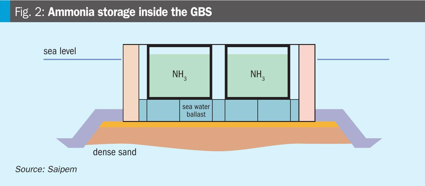
Various types of ammonia storage systems have been built onshore (e.g. single containment with low bund wall, double containment with outer concrete wall, etc.). However, the necessity of building new large capacity storage tanks and minimising at the same time the risks for ammonia toxic dispersions, has paved the way for the application of ammonia storage inside the GBS hull, an inherently safer solution which is also allowing to obtain large storage capacities in a compact footprint.
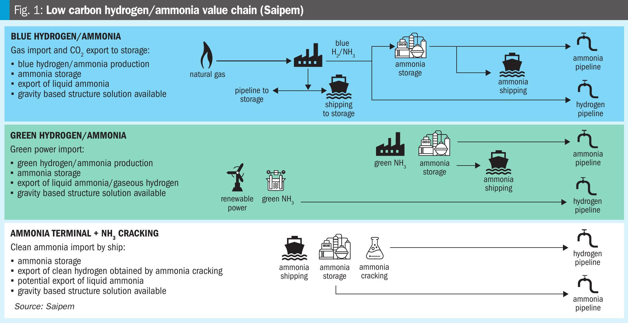
The low carbon hydrogen/ammonia value chain is enriched by the possibility to implement GBS solutions either in the production of blue or green ammonia as well as the import terminals of low carbon ammonia, ref. Fig. 1.
Ammonia storage in a GBS
Historically, Saipem has executed EPC projects with various refrigerated liquified gases stored inside a GBS. In addition, Saipem has designed and built onshore ammonia storage tanks. The adoption of a GBS solution to accommodate the ammonia storage functionality represents a natural evolution combining the above experiences and a way to address mainly safety aspects, social perception of ammonia toxicity and logistic/ infrastructures constraints.
The GBS consists of a concrete hull, laid on the seabed in the near shore. It can contain a portion of the plant inside its hull and the remaining portion on its top slab, including the ammonia production or cracking facilities and relevant utilities, required buildings and the direct berthing and mooring facilities of large vessels (Fig. 2).
Safety related mitigation measures
The toxicity of ammonia has been the major preoccupation for designers and operators of liquid ammonia tanks in the industry, requiring efficient preventive measures to avoid possible causes of ammonia release to the environment. Addressing stress corrosion cracking, advanced types of crack monitoring systems have been developed (e.g. acoustic emission sensors and robotised in-service inspections) for ammonia primary containers thus engaging the operators as well to have special respect for the internal inspection intervals and maintenance scheme of such storage tanks.
Leak risks and toxic dispersions are significantly mitigated in the case of GBS since the ammonia storage tanks are situated inside the GBS hull, fully contained in a stand-alone metallic tank and surrounded by secondary and tertiary barriers of pre-stressed concrete walls in the horizontal direction as well by the GBS bottom and top slabs in the vertical direction. The second barrier is liquid-tight, and it can be designed to become vapour-tight by installing an adequate vapour barrier on the inner face of the concrete components. The third barrier is liquid-tight ensured by the prestressed concrete walls.
These multiple layers of protection drastically reduce the risk of accidental ammonia release into the environment.
Reasons for implementing the GBS concept
GBS solutions have been successfully deployed in the offshore oil and gas industry for more than 30 years.
GBS is a robust, flexible, adaptable and proven asset to overcome onshore constraints and provide an effective and safe solution for the storage of various refrigerated liquified gas applications such as LNG, LPG and ethane.
In particular, the conventional onshore installation of ammonia storage in the proximity of densely populated areas could represent a major concern in respect to the social perception of ammonia toxicity. GBS could unlock the feasibility of the project with respect to this major constraint.
Being a “3-in-1″ solution, the GBS concept allows the entire integration of all topside structures and modules necessary for green/blue ammonia production or ammonia cracking or storage facilities on a single concrete hull that contains the liquid ammonia (LNH3) storage tanks, each one with direct berthing and mooring facilities of large vessels.
GBS option A (blue ammonia production) will host, in addition to LNH3 storage tanks, the entire ammonia production unit consisting of synthesis gas generation (based on steam or autothermal reforming) and ammonia synthesis loop and refrigeration. Captured liquid CO2 storage and shipping facilities or CO2 pipeline for export will be also installed on the GBS.
In option B (green ammonia production) hydrogen generation facilities via electrolysis of water will be installed on the GBS together with the ammonia synthesis loop and LNH3 storage tanks; the potentially unlimited water source represented by sea water will be exploited by means of desalination units feeding electrolysers with water at the requested purity specifications.
In option C (ammonia cracking) commercial grade liquid ammonia will be delivered by ships, stored in LNH3 storage tanks and from here pumped to ammonia cracking facilities producing and exporting high purity hydrogen at the requested pressure level. Process schemes have been developed to crack ammonia with zero CO2 emissions and minimum use of utilities and no steam generation, import or export.
The advantage of using ammonia cracking on the GBS is also to reduce the length of the connecting pipe to the ammonia storage that is basically built under the ammonia cracking plant thus also allowing, in case of need, to safely and easily drain the ammonia cracking lines in the storage.
In option D, the GBS solution represents an ammonia terminal, GBS containing ammonia tanks, which could be entirely built in dedicated yards.
For all the options, ammonia ship could moor directly on the GBS to load or unload the ammonia.
Available and proven technologies for ammonia production and cracking can be adopted for GBS application without any modification relevant to technology considering that the stability of the GBS allows installations similar to the onshore ones. Depending on the location of the GBS, its distance from the coast, certain specific features may vary to cope with the marine environment.
Another reason for implementing a GBS solution is the possible advantages compared to clean hydrogen export via pipelines. GBS can significantly contribute to the ammonia value chain by supporting ammonia storage and cracking applications for hydrogen production. In view of the current lack of a well-developed infrastructure for hydrogen offtake, transport, and storage, it can also be utilised for inland hydrogen distribution systems or for the direct generation of thermal power. In a typical harbour setting, this scheme of large-scale storage can be possibly used for bunkering vessels with LNH3 or LH2 as fuels.
This solution provides flexibility because (1) hydrogen or ammonia feedstock can be sourced from various locations, (2) hydrogen demand is currently unstable and GBS can scale in increments while a pipeline must be constructed for future demand, and (3) geopolitical conditions may influence energy sources and demand.
GBS offers flexibility and adaptation to market conditions. GBS also provides a robust solution. The architecture of GBS is designed to provide a strong structure essential for ammonia storage. A standalone solution with zero or minor onshore space requirement, the GBS benefits from high resistance to extreme environmental conditions rendering it suitable for harsh environments. Industrial safety risks are significantly reduced due to the positioning of all equipment, piping, and ammonia process systems nearshore or offshore, sufficiently distant from populated areas. As LNH3 storage is near atmospheric pressure, the explosion risks are also limited. In the worst-case scenario of a high-speed collision causing significant local damage to the GBS caisson, this would never result in loss of the primary containment due to the wide buffer compartment corridors that entirely enclose the ammonia tanks all along the GBS perimeter and act as lines of protection against external boat impact.
A major advantage of GBS is that most of the construction works can be performed safely and efficiently in controlled environments, whether at the GBS construction yard or at the fabrication yards of topside modules and LNH3 tanks.
After the completion of GBS civil works and the integration of topside modules, the GBS can be floated out from its construction yard, towed, positioned, and sunk at its installation site with very minimal on-site works (permanent ballasting, hook-up, commissioning, and ready-for-start-up). The GBS design can be reproduced with minimal customisation and relocated at any time during its service life due to its classical ballast system, which requires little maintenance.
The modularisation of ammonia facilities has been extensively optimised by Saipem and is currently being implemented in an ongoing EPC large-scale, ATR-based ammonia plant (see Fig. 3).
Modularisation provides benefits in terms of safety and costs for locations where mobilising a large construction workforce is not feasible, or where site access is challenging or restricted for extended periods.
An analysis of module size, considering logistics, cost, time, and yard availability, was performed to optimise the execution strategy.
In a GBS solution, the plant topsides can be modularised to a very large extent, and the entire solution can be mostly developed in pre-selected yards, thus reducing risks and impacts related to safety, quality, severe weather conditions, local workmanship, cost and schedule. The remaining activities to be stick-built on site can be of similar typology to flare assembly and installation, insulation works and commissioning of LNH3 storage tanks, installation of E&I cables on interconnecting pipe racks, gangway tower installation, standby generators placement, and final hook-up works.
Reference projects
Building large-scale gravity-based structures with Ammonia storage leverages previous projects and extensive experience in GBS and onshore ammonia storage tanks. In the next section, two recent projects are highlighted in order to serve as reliable references for Saipem’s proposed configuration.
Reference project: GBS FEED and EPC
Recently, in order to support natural gas pre-treatment and liquefaction needs, three large-scale GBS units (3 x 6.7 t/a LNG trains) were designed for construction, with a total storage capacity of 229,000 m3 of LNG (2 tanks x 114,500 m3) per GBS as well as 1 tank x 75,000 m3 of liquid condensate and 1 x 960 m3 of ethane, to be all contained within the GBS structural hull.
Each LNG train is hosted on a single GBS and consists of several topside modules.
As part of this project, Saipem has carried out extensive FEED activities including engineering and constructability studies. Following the FEED phase, Saipem was responsible during the EPC phase for the detailed engineering and overall completion of civil works for the GBS structural hull as well as for the design and installation of the cryogenic storage systems. Each GBS was constructed in a graving dock with more than 150,000 m3 of concrete per GBS, and then safely towed-out for approximately 1,100 km to its destination.
Reference project: GBS feasibility study
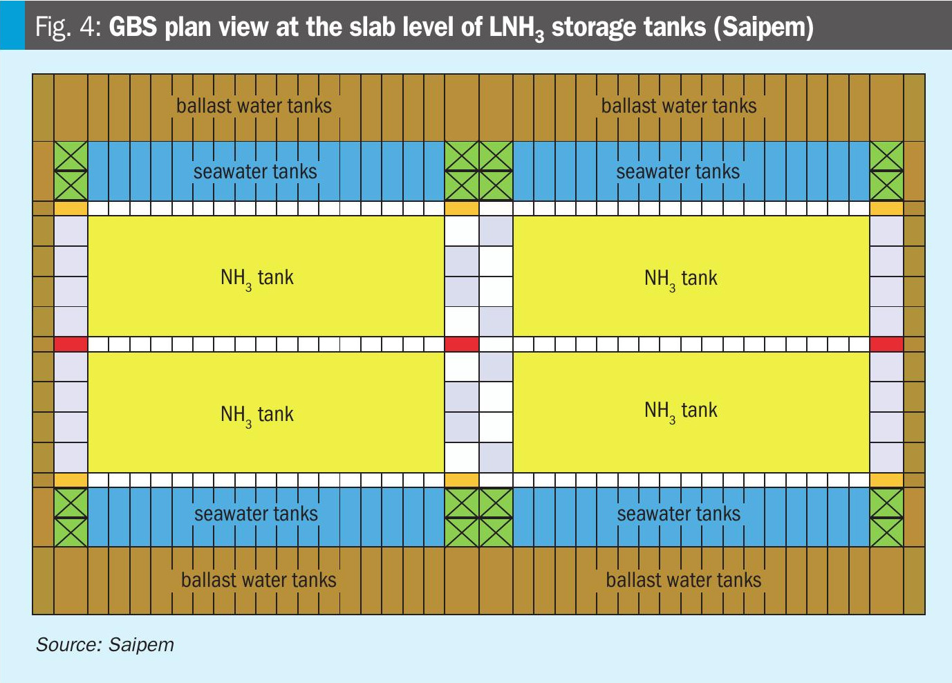
For another project, a techno-economic feasibility study was conducted by Saipem for an ammonia facility comprising two identical ammonia cracking trains, each capable of producing up to 150,000 Nm3/h of pure hydrogen product based on 2,400 t/d of ammonia feedstock. The facility also comprises associated utilities, technical buildings and rooms, auxiliary equipment, living quarters, platforms, and all necessary interconnecting pipe racks to ensure fully independently operable systems. The GBS has the capacity to hold up to 300,000 m3 of LNH3 within its hull, facilitated by multiple low-temperature storage tanks.
The GBS plot plan elaborated at the end of this study was developed based on experience and lessons learnt from Saipem’s GBS projects. The monolithic concrete GBS is 328 m long and 152 m wide at the base. Its height is adjusted for floatability, stability, and to meet or exceed the required ammonia storage volume.
Fig. 4 displays the GBS plan view at the ammonia tanks level. Yellow rectangles indicate the ammonia tanks, brown areas are solid ballast tanks, and blue areas represent seawater ballast tanks. The green compartments are designated for utilities storage of other products. The remaining compartments will accommodate access ladders, stairways, ballast pumps, LNH3 transfer pump rooms, dry compartment corridors, and other necessary infrastructure.
Saipem experience
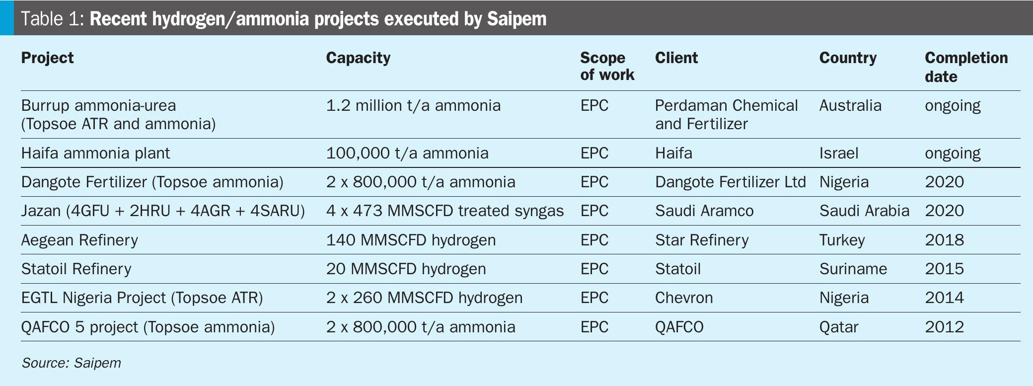
Saipem is one of the world leaders in the execution of hydrogen/ammonia projects in the last 60+ years. Table 1 shows the recent hydrogen/ammonia projects executed by Saipem.
Saipem can also draw on its vast experience in the design and construction of gravity based structure solution:
• More than 25 years experience in EPC projects with concrete and GBS marine applications.
• More than 350 concrete caissons (<40 m) installed.
• Several large scale (>100 m) concrete structure.
Saipem excels in designing and constructing the whole ammonia complex including ammonia storage facilities. With experience in executing over 130,000 km of pipelines and expertise in gaseous hydrogen and liquid ammonia studies, Saipem is also a major player in offshore and drilling sectors, leveraging its own floaters and ships. This comprehensive capability is crucial for completing the ammonia value chain from production to distribution.
Conclusions
This article has presented some projects which build on Saipem’s EPC expertise to design and construct large-scale nearshore GBS with low temperature/cryogenic products storage, such as LNG and LNH3.
Saipem GBS solutions are flexible and adaptable to project specific needs. Most construction activities can be performed in a well-protected and controlled environment, whether at the GBS construction yard or in the fabrication yards of topside modules, LNH3 tanks, and other large mechanical outfitting elements.
The GBS concept enables the complete integration of the LNH3 storage system within a single concrete hull, enclosed in multiple concrete barriers, offering a safer solution than conventional onshore systems.
In case production of clean hydrogen is required, an ammonia cracking plant with zero CO2 emissions can be installed on the topside of a GBS, acting thus as an import terminal of clean ammonia and export terminal of clean hydrogen. This solution is highly effective, particularly in Europe, considering the expected increase of ammonia import and the high demand for clean hydrogen.