Nitrogen+Syngas 363 Jan-Feb 2020

31 January 2020
Methanol routes to a lower carbon footprint
GREEN METHANOL
Methanol routes to a lower carbon footprint
‘Green’ methanol means many things to different people. It encompasses low carbon emissions methanol manufacture at scale, recovery of material through waste gasification and conversion to methanol and power to liquid (e-fuel) methanol via electrochemistry and sometimes a combination of all of the above. Each route has a place in reducing the overall carbon footprint of production and subsequent use of methanol, driven by both governmental incentives or societal demand. In this article Andrew Fenwick of Johnson Matthey reviews the various routes to manufacture.
Drivers for green chemicals
In common with the rest of the syngas community, the producers of methanol are being encouraged by society to reduce their emissions at point of manufacture and if used as a fuel or fuel component, in use.
Global energy demands are increasing and so too is the need for more renewable and sustainable sources of energy to help transition us to a post-fossil fuel powered world. Increased energy efficiency is one of the simplest means of reducing our primary energy usage but increased renewable or zero carbon energy vectors will also be required if we are to maintain similar (or aspired) standards of living.
Governments are responding to this challenge by mandate. For example, in 2018 the EU increased its renewable energy target to 32% by 2030, with many countries planning to ban fossil fuel powered cars by 2040. It is also increasingly likely that we will need to significantly decrease our net equivalent carbon dioxide (CO 2 ) emissions by increasing our use of carbon capture and storage (CCS) of CO 2 and where storage of CO 2 is not possible, then carbon capture and (re)-use (CCU).
Government mandates for fuel blending quotas and incentives for renewable fuels as well as carbon taxes should have an impact on the willingness of the market to pay a premium for renewable methanol. In Europe the policy driver is the EU’s Renewable Energy Directive (RED), which was revised (RED II) in December 2018. The EU RED II and Fuel Quality Directive (FQD) classify renewable methanol from non-biological sources as a renewable fuel. The UK, since 2008, has introduced its Renewable Transport Fuel Obligation (RTFO) scheme. Fuels that are categorised as Renewable Fuels of Non-Biological Origin (RFNBO) are incentivised by awarding double credits per litre or kilogram supplied. These credits are known as Renewable Transport Fuel Certificates (RTFCs) and can be traded between suppliers of fossil transport fuels or eligible biofuels. In terms of CO 2 tax, in the EU a cap-and-trade system was introduced in 2005, the European Trading Scheme (ETS), for the trading of carbon emission credits. The Republic of Korea, the Chinese province of Guandong and the US state of California have also implemented cap-andtrade programs.
Additionally the IMO has announced aspirational targets “to reduce CO 2 emissions per transport work, as an average across international shipping, by at least 40% by 2030, pursuing efforts towards 70% by 2050, compared to 2008”. The use of methanol in these large marine engines has been ably demonstrated recently and the use of green methanol will accelerate this sector’s push for lower emissions. Methanol will have an advantage over LNG in that it is bunkered in more ports and is easier to convert existing ships to than LNG.
One of the largest users of energy is as fuel in the transportation sector. There are a few main routes to a sustainable source of energy for this sector:
- Route 1: Renewable or non-carbon emitting electricity can be harnessed to power vehicles, with energy stored in batteries on board. However, certain transportation modes such as aircraft, heavy-duty trucks and marine vehicles demand a high power and energy capacity that are currently unmet by battery storage alone.
- Route 2: Alternatively, renewable electricity can be utilised to electrochemically convert one chemical to another with a higher energy potential. The most well-known of these is the conversion of water to hydrogen (H 2 ). Low carbon hydrogen can also be produced from natural gas using a combination of steam reforming and water gas shift, followed by capture and storage of the CO 2 . As the energy density of the final fuel (H 2 ) is low, this significantly reduces the range of aeroplanes and ships, without significant storage volume. This is where the next two options can be useful.
- Route 3: Waste or biomass can be converted into chemicals or fuel, typically through a syngas intermediate or pyrolysis step. Pyrolysis can convert hydrocarbon sources but has the disadvantage of creating a wide range of final products which need separation and/or blending before final use.
On the other hand, gasification is a flexible process to convert a wide range of waste hydrocarbons/biomasses to synthesis gas (syngas), a mixture of gaseous hydrogen and carbon oxides, from which useful chemicals or fuels can be efficiently produced.
- Route 4: Lastly, the combination of carbon monoxide and/or carbon dioxide with hydrogen derived from electrolysis, can be utilised to produce the same chemicals or fuels. Other variants of electrolysis include co-electrolysis of carbon dioxide and water to syngas and even further, to final products e.g. methanol, methyl formate and ethylene.
Forming part of a suggested future of zero net emissions, the “methanol economy” would look to utilise both renewable electricity and also waste CO 2 that would otherwise be emitted to the atmosphere or captured for sequestration. It is envisaged that methanol, utilised as a fuel, or fuel building block, can bridge society’s need to reduce its net carbon dioxide emissions.
The choice of product is a consequence of process economics and market demand. As GHG emission reduction often plays an integral part, a full life cycle assessment (LCA) is required to confirm CO 2 mitigation benefits, taking into account the whole value chain from CO 2 origins to the final use of the product. The production of methanol is an attractive choice, since it has many uses. ‘Green’ methanol can be used as a fuel, for example in the M15 blends common in China, or as an energy carrier for hydrogen. Both these applications benefit from the high energy density of methanol (16 MJLHV/litre, about half that of diesel). Methanol can be converted into higher performance fuels, e.g. by the ExxonMobil methanol-to-gasoline process (or equivalent), or via molecules such as dimethyl ether. In addition, methanol is well established as a chemical intermediate for important molecules such as formaldehyde. Fuel applications are perhaps best placed currently to benefit from incentives, and the larger fuel pool gives the potential for greater impact on CO 2 levels than chemicals production.
Low carbon methanol
Operators of large scale methanol plants are constantly looking to improve the economics of production. Licensors of methanol technology, including Johnson Matthey (JM), have risen to the challenge by improving the feedstock efficiency of their designs. This has the natural renewable energy power natural gas MP boiler steam fuel consequence of decreasing carbon emissions, as the typical non product use of feedstock is as fuel to provide heat and power for the overall process. In order to largely eliminate the carbon emission at point of manufacture, the operator has three choices:
- capture the emitted CO 2 and sequester it;
- use a fuel which does not produce (net) CO 2 as a combustion product e.g. H 2 or bio-derived fuel or;
- utilise a process that imports power and heat from an external renewable source.
Capturing of CO 2 from the flue gas of conventional natural gas based plants is already undertaken at QAFAC, Qatar and GPIC, Bahrain but these plants primarily have been designed to increase the throughput of the plant, not to totally eliminate the CO 2 emissions. The parasitic load of the CCU unit is slightly outweighed by the efficiency gains of balancing the stoichiometry of the syngas but the overall efficiency gain is modest and net CO 2 emissions are not significantly better. In principle, all the CO 2 could be captured from the flue gas of the methanol plant and any CO 2 not utilised within the process, exported for sequestration.
CO 2 capture is also practiced on all gasified coal methanol plants but in this instance the CO 2 is captured in order to correct the stoichiometry of the produced syngas. The captured CO 2 is then vented to atmosphere and the CO 2 emissions per tonne of product methanol is significantly higher than that from a natural gas based plant.
A second option of utilising H 2 as the fuel source is likely to be the most economic for existing methanol plants, in order to eliminate CO 2 emissions. Most oxygen methanol natural gas based plants have suitable fuel and burner systems to utilise pure H 2 as fuel without significant modification, as they already burn significant quantities of methanol loop purge gas, rich in H 2 . The simplest route for an existing plant would be to capture CO 2 from the existing syngas in the syngas section, resulting in an excess of H 2 and that excess H 2 utilised as the fuel source. This would however reduce the output of the methanol plant.
Another option would be to build a new dedicated H 2 plant, where the CO 2 is captured at pressure, reducing the parasitic load of the CCS unit. In JM’s opinion, this would best be practiced by utilising a GHR/ ATR H 2 plant. Alternatively, the H 2 could come from electrolysis (see later sections) which would have the advantage that the existing plant could be uprated, should it currently be feedstock limited.
The BioMCN ™ methanol plant in the Netherlands already utilises feedstock/ fuel derived in part from biogas. Biogas is typically a 60:40 mixture of CH 4 :CO 2 , derived from the fermentation of biomass. Most existing biogas is utilised as fuel for electricity generation, as the sources are dispersed geographically. Governments such as the Netherlands and the UK are looking to significantly increase their biogas production, and as the feedstock becomes more widely available, the syngas industry is likely to increase its consumption and hence reduce its net carbon emissions significantly.
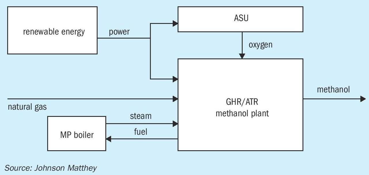
For new plants that don’t have access to bio-derived feedstocks or are sited where the geology is not suitable for sequestration of CO 2 , they can be futureproofed by having a plant design such as the Johnson Matthey GHR/ATR methanol plant (Fig. 1), as utilised at Coogee Chemicals plant in Australia. This plant largely eliminates the CO 2 emissions at point of manufacture, as the energy required from compression and heat is supplied from external electricity sources. The Johnson Matthey GHR/ATR methanol plant also significantly saves on water utilisation, as the cooling load is also greatly reduced compared to ATR only or SMR/ATR designs.
Gasification of waste (or biomass)
Gasification of municipal solid waste (MSW) can reduce net equivalent CO 2 emissions by reducing the potential of methane emissions from the landfill, as biomaterial can biodegrade to methane when in the ground. Gasification or incineration of the MSW will eliminate this potential vent.
Gasification of waste (or biomass) and conversion to methanol will compete for feedstock with energy recovery by incineration or conversion to other more valuable end products e.g. Fischer Tropsch conversion to naphtha/kerosene/diesel. Key to the success of gasification technology will be the performance of the gasification unit versus the varying calorific values of the constituents to be gasified. To produce a syngas that is suitable for conversion to methanol, higher temperature gasification is generally required, in order to minimise the formation of methane in the gasifier.
Most gasification plants produce a syngas that is sub stoichiometric in hydrogen, and hence excess carbon is usually removed as CO 2 downstream of a water gas shift unit. This acid gas removal unit also removes the majority of the H 2 S/ HCl formed in the gasifier but other key poisons such as HCN will also need to be dealt with. The CO 2 emissions from a gasification plant can be considerably higher than for a natural gas based plant, on a per tonne of methanol basis, unless the captured CO 2 is also sequestered.
Addition of an external H 2 stream can adjust the stoichiometry of the syngas, considerably reducing the CO 2 emissions and in principle, remove them completely. This can be advantageous if the gasified material is limited in supply. Reducing or eliminating the emission of CO 2 will consequently increase the production of the product methanol. Methanol as a final product in this instance has an advantage in that both the CO and CO 2 can be converted to final product, utilising all the carbon in the feedstock, maximising the value of the limited feedstock.
The addition of this extra H 2 will mean the adjustment of the operation and design of the acid gas removal unit and the elimination of the shift unit. Dealing with the residual catalyst poisons may become more difficult, without the operation of the acid gas removal unit.
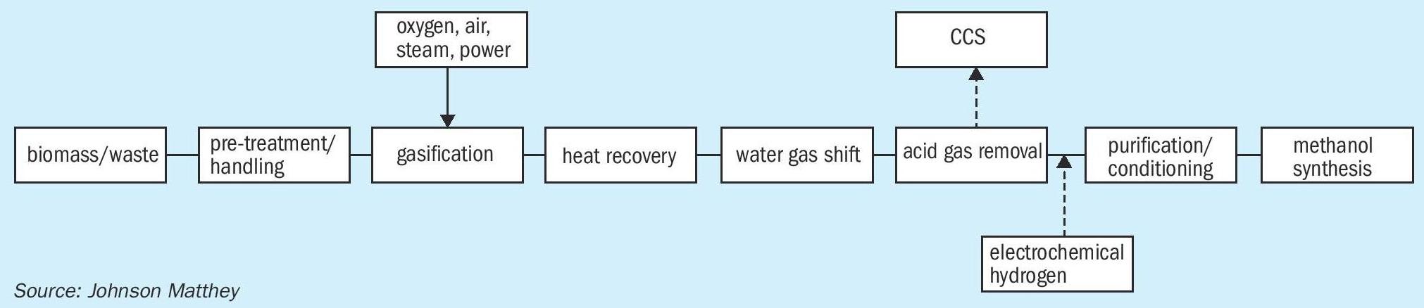
Fig. 2 shows a typical gasification route to methanol.
A number of new projects have been announced recently e.g. ENI Livorno and this process is already commercially in operation since 2016 at the Enerkem Inc. facility in Edmonton, Alberta, Canada.
The economics of gasification of municipal solid waste can be considerably improved by the avoidance of waste tipping fees. These ‘gate fees’ can compensate for the lower renewable fuel incentive if the material to be gasified is low in biomass.
Power to methanol
In seeking to reduce the world’s dependence on fossil fuels and associated greenhouse gas (GHG) emissions, methanol production using electrochemistry has certainly provoked much research interest in recent years and is an already demonstrated concept. Forming part of a suggested future “methanol economy” this would look to utilise both renewable electricity and waste CO 2 that would otherwise be emitted to atmosphere or captured for sequestration.
The alternative production of fuels and chemicals such as methanol, which are traditionally made from fossil fuel feedstocks, by employing wind, solar photovoltaic, hydro or geothermal electricity can also help to address the problem of storing this often variable energy whilst balancing the grid and utilising cheap electricity when generation exceeds demand.
Schemes such as this are known as power-to-fuels, solar-to-fuels or power-togas. Many of them rely on a two-step process involving water electrolysis to produce hydrogen, which is used for thermocatalytic reduction. In the case of CO 2 , various product options are available including syngas, formic acid, methanol, methane or higher hydrocarbons. Electrolytic hydrogen can also be used to reduce nitrogen to ammonia. An alternative scheme would be to use the renewable electricity for the direct electrochemical reduction of CO 2 and water (coelectrolysis) to the aforementioned fuels and chemicals. One question that arises is which fuels or chemicals industry should target for production: beyond methanol, a range of other molecules have been produced from electrochemical reduction of CO 2 at the research scale. These include ethylene, methane, formic acid, ethylene glycol, propanol and ethanol. This has the attraction of using a single reactor but is more technically challenging and less well-developed.
One further aspect to consider is the inherent intermittency of some renewable power sources such as wind and solar photovoltaic. Without direct connection to the electricity grid or a form of energy storage the plant economics suffer, often requiring a high annual plant utilisation (high on-stream factor).
The energy requirements of these systems can be illustrated by the case of electrolytic hydrogen production followed by thermocatalytic CO 2 reduction. The electricity required for a water electrolyser operating at 2 volts and with 100% faradaic efficiency is 191 GJ (electric) /tonne (hydrogen) (53 kWh/kg). The direct CO 2 hydrogenation reaction for methanol synthesis can be represented overall by equation (1), assuming that the CO 2 is ultimately converted to methanol, with any carbon monoxide formed via the reverse water-gas shift reaction also being hydrogenated to methanol.
CO 2 + 3H 2 = CH 3 OH + H 2 O (1)
For an ideal stoichiometric conversion of hydrogen then the equivalent electricity consumption rate is 36 GJ (electric) / tonne (methanol) (10 kWh/kg). This energy demand for the electrolyser is similar whether the methanol is produced by CO 2 hydrogenation using electrolytic hydrogen or directly through the co-electrolysis of CO 2 and water. Variations in electricity consumptions between the two routes will be due to different operating voltages and faradaic (or current) efficiencies for the electrochemical unit operations, slip of oxygen into the hydrogen stream, compression duties and any inefficiencies for the downstream operations for deriving pure methanol (e.g. synthesis loop carbon efficiency, product separation and purification). Including those losses, a more realistic value for early adopter plants might be 13 kWh/kg.
The electricity consumption for the electrolysis step contributes a significant fraction of the overall methanol production cost. Referencing electricity prices derived from fossil fuels for G20 countries in 2017 of between $0.05/kWh – 0.17/kWh, then taking an average cost in the United States in 2017 of $0.07/kWh, the minimum electrolyser energy costs (operating at 2 volts) are $700/tonne (methanol) . Taking a low value in 2017 for on-shore wind of $0.03/kWh this then reduces to $300/ tonne (methanol) . However, solar and solar/ wind combination farms are now guaranteeing electricity at $0.02/kWh which reduces the cost to $200/tonne (methanol) .
This value increases to $260/ tonne (methanol) , including losses mentioned above, equivalent to a natural gas cost of $8.3/million Btu (HHV) for a conventional plant (~31.3 million Btu/tonne including fuel). Additional variable and fixed plant expenses including capital charges will also need to be accounted for in the overall production cost, thus renewable methanol will generally be costlier to produce and need to command a premium value, compared to conventional fossil fuel derived methanol (dependant on natural gas price). For such schemes, plausible economics could exist but would need to be evaluated on a case-by-case basis with the local availability of inexpensive renewable electricity and a source of clean CO 2 being fundamental requirements. From the stoichiometric mass balance using equation (1), the CO 2 specific consumption rate is approximately 1.4 tonne (CO2) /tonne (methanol) , which would be an input for the life cycle assessment to establish the carbon footprint and climate change mitigation to compare with conventional methanol for fuels and chemicals.
This power requirement and the fact that the largest water electrolyser modules are currently available at 2-3 MWe per stack, already supports a view that localised small-scale electrochemical plants would initially be the focus, rather than compete directly with world-scale conventional methanol facilities (typically 5,400 t/d). Additionally, electrochemical processes tend to scale linearly when compared with large thermal-catalytic processes akin to fossil-fuel methanol, which can exploit the reduced production costs from the economies of scale, so the economics of a project may be dominated by external incentives until the technology matures and average generation costs come down for the electricity.
For the previous example with a $260/ tonne (methanol) electricity cost, it will only achieve parity vs a typical natural gas based plant with a 3$/million Btu (HHV) natural gas price, with a CO 2 e credit of ~120$/te CO 2 e, given that the specific consumption rate of CO 2 is 1.4 tonne (CO2) / tonne (methanol) . Other incentives such as renewable fuel use requirements may mean that the methanol produced can realise a premium vs methanol produced via a non-renewable route. It may also be recognised that a large proportion of a final gasoline or diesel price is often government levies that could be waived.
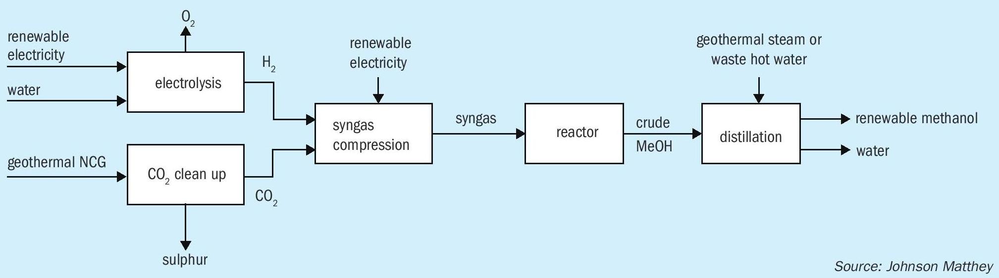
An example of an already operating commercial facility producing renewable methanol is that owned and operated by Carbon Recycling International (CRI). The George Olah (GO) plant is located in Iceland’s Svartsengi geothermal field near Grindavík on the Reykjanes peninsula. The plant was first commissioned in 2012 with a capacity of 1,300 t/a of renewable methanol and was expanded in 2015 delivering 4,000 t/a. It utilises captured CO 2 from the nearby Svartsengi geothermal power station and renewable electricity from the Icelandic grid to produce electrolytic hydrogen for use in methanol synthesis (Fig. 3). The methanol is used in gasoline blends with the GO plant utilising 5,500 tonnes of CO 2 per year. The renewable methanol product from this facility is sold under the brand name of Vulcanol ™ and is displacing a small amount of fossil fuels in the transport sector. The renewable methanol fuel blends are for sale in Iceland and other countries including Denmark, Sweden and The Netherlands. The renewable methanol produced was the first renewable fuel from non-biological origin to be certified according to the International Sustainability & Carbon Certification (ISCC) Plus, with GHG savings of up to 90% when compared to gasoline.
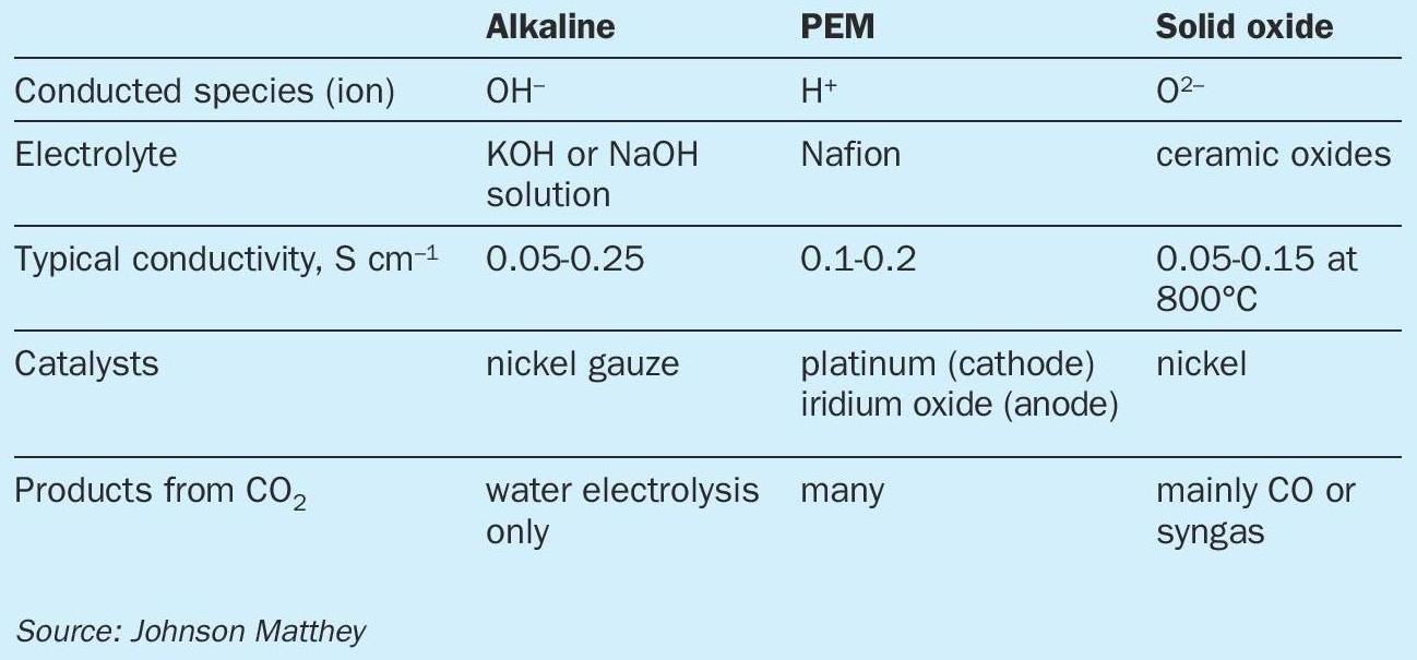
Electrolyser types
There are three main types of electrolysers, all of which can play a role in the synthesis of renewable methanol. The first of these is alkaline electrolysers, which have been commercially available for a number of years. These use nickel electrodes at temperatures below 100°C to split water from a strongly alkaline electrolyte, typically over 20% potassium hydroxide, with a porous separator between the electrodes to stop electrical shorting across the electrodes. Modern alkaline electrolysers are typically available in cells of 1-3MW, which are coupled together into stacks of up to 100MW. The lifetime of these systems can be over 80,000h.
PEM electrolysers (Proton Exchange or Polymer Electrolyte Membranes) work in a similar temperature range to alkaline systems. The key difference is the use of a solid state polymeric electrolyte such as Nafion which conducts protons well when hydrated with water. The electrode catalysts are coated onto each side of the electrolyte, and gas diffusion layers added to ensure good dispersion of the gas across the two electrodes. Unlike the alkaline electrolyser, the PEM system has two different catalysts: typically Pt-based catalysts for the reduction of protons to hydrogen at the cathode, and iridium oxide-based materials for the oxidation of water at the anode. The use of precious metals is generally required due to the harsh operating conditions in the electrolyser, with low pH and strongly oxidising electrochemical environment. Research is ongoing into non-precious metal catalysts, but stability over the desired long lifetime is an issue. The main advantage of PEM electrolysers over alkaline is that they can run at higher current density (reaction rate) and hence can produce more hydrogen per square metre of footprint. PEM electrolyser devices tend to be 1-2 MW in size and have been coupled to 100 MW systems.
An alternative low temperature approach is to use PEM-like systems but at high pH. In this case, the conducted species is not the proton but the hydroxide ion. Much progress has been made on the conductivity and stability of AEMs but none has emerged with the ubiquity of the Nafion ionomer for protic environments. One advantage of using an alkaline environment is that a greater range of materials can be used as catalysts and for other roles in the cell.
The final class of electrolysers which can be used in the synthesis of renewable methanol are solid oxide electrolysers. These are based on thin ceramic electrolytes, which have good conductivity for oxygen ions at high temperatures such as 800°C. The catalysts tend to contain base metals such as nickel, whilst electrolytes are often yttria-stabilised zirconia (YSZ) or doped cerias such as gadolinium-doped cerias (GDC). One key advantage of the solid oxide system is that it can be very energy efficient if heat integration can be used advantageously in other parts of the system. Solid oxide systems are less well-developed than alkaline or PEM electrolysers, and system sizes tend to be smaller.
Electrochemical systems
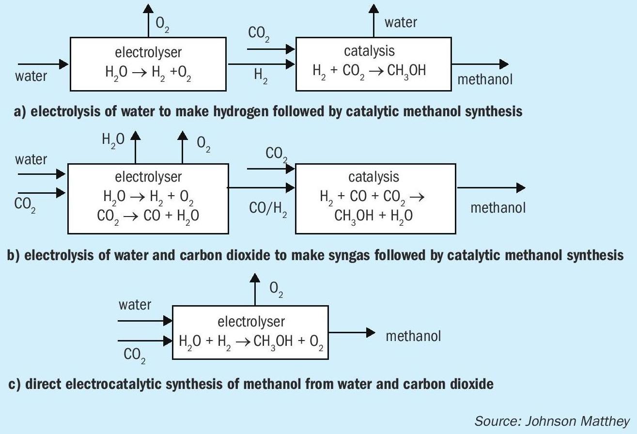
There are various methods for incorporating electrolysis into processes for the synthesis of renewable methanol (Fig. 4). Perhaps the simplest and closest to market is to use electrolysis to produce hydrogen from water, followed by catalytic reaction with CO 2 to make methanol. A range of electrolysers for the production of hydrogen are commercially available, and as well as the CRI renewable methanol facility in Iceland a range of pilot schemes are in place aiming to make renewable methanol and other basic chemicals such as ammonia.
A second approach to the synthesis of renewable methanol is to make both components of syngas, CO and hydrogen, by electrolysis, and then convert the syngas to methanol using the conventional catalytic approach. Electrolysers for the reduction of CO 2 are less well-developed than those for water electrolysis, although a number of companies are working in the area. CO production by electrolysis has been demonstrated at lab scale using both solid oxide and PEM technologies.
The direct production of methanol by co-electrolysis has also been demonstrated at lab scale using PEM electrolysis systems. In principle this presents an advantage by using the smallest number of reactors. However, getting good efficiency at high enough reaction rates has proven to be challenging and there is a significant amount of scientific endeavour dedicated to better understanding and utilising electrolysis for the conversion of CO 2 to useful products such as ethylene, methanol and methane. In general, solid oxide cells are not preferred in this application because methanol tends to decompose at high cell temperatures.
One factor worth noting is that the amount of electricity (number of electrons) is the same in each case: six electrons per molecule of methanol. The various methods differ in whether they use hydrogen as a carrier for the electrons, or whether and to what extent they are transferred directly to the CO 2 . The efficiency of the different electrolysers and the temperature range of operation will also be a factor.
Catalysts for the direct synthesis of methanol
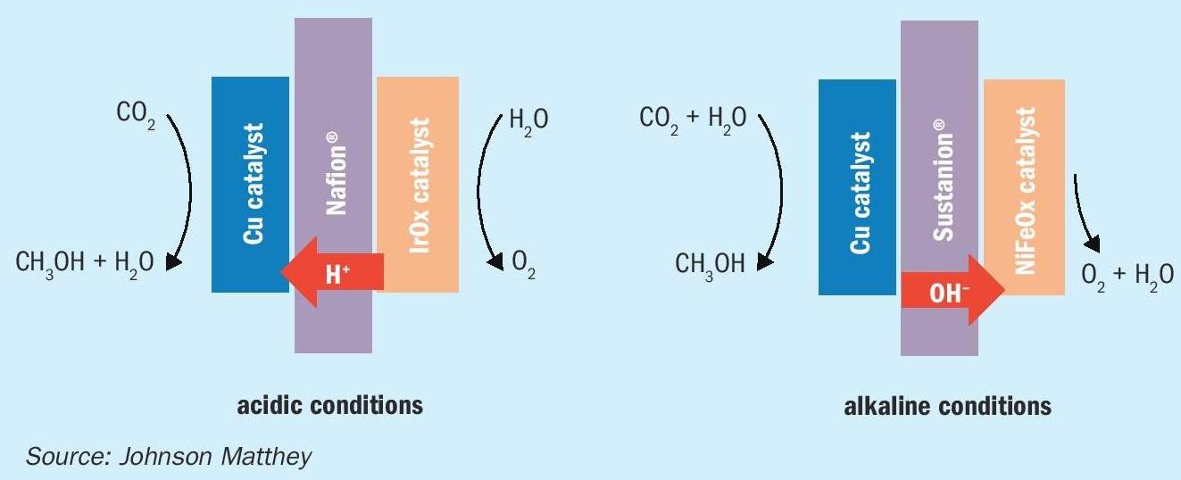
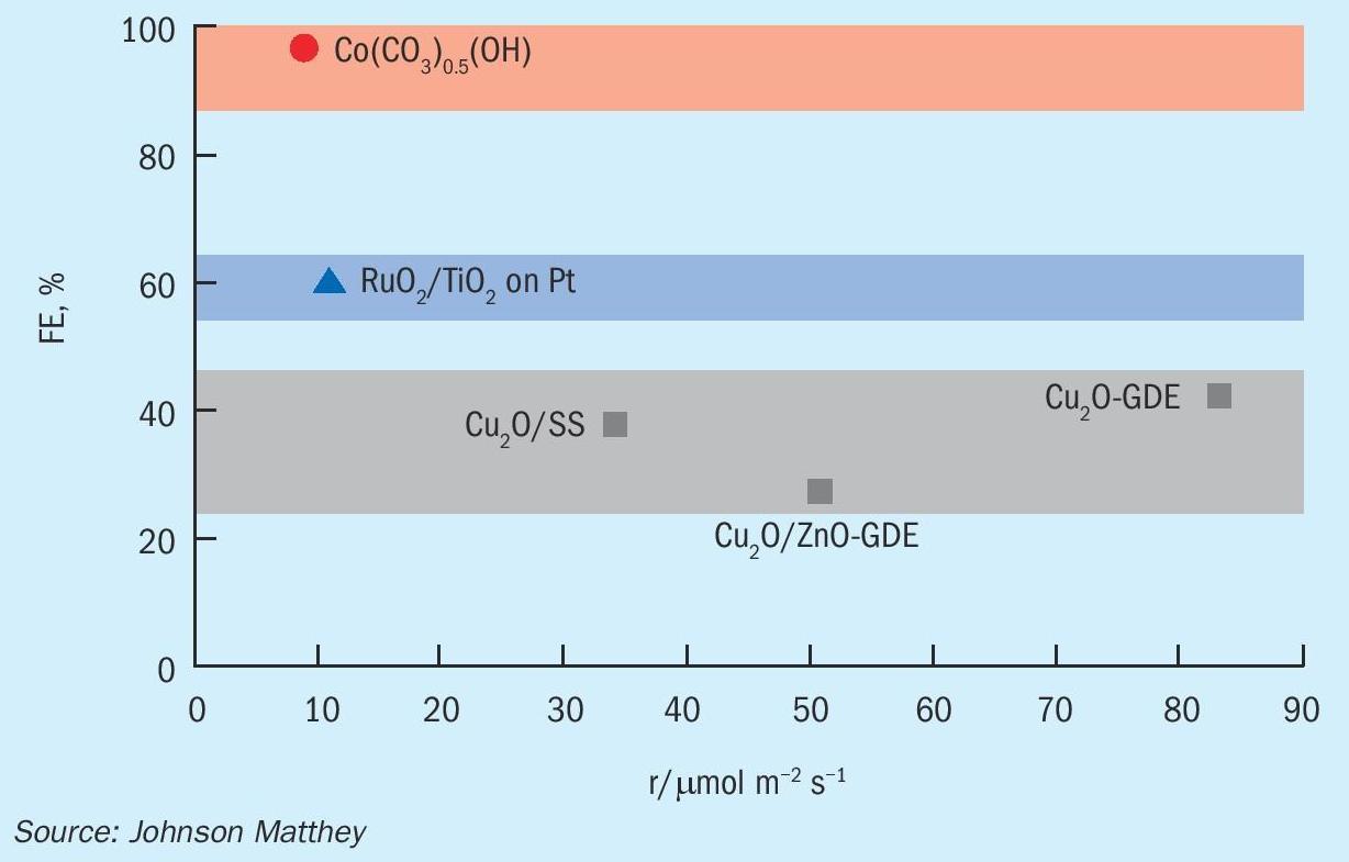
Systems are being developed which allow CO 2 to be reduced to methanol, in situ. These can be run in acidic or alkaline conditions, with slight differences depending on the conditions chosen. In acidic conditions, the conducted species is H+ whilst in alkaline it is OH-. This has consequences for the reaction mechanism and the configuration of the cell, as shown in Fig. 5. There is a small body of literature surrounding the electrochemical reduction of CO 2 to methanol, and comparisons between catalyst performances is difficult due to variations in reaction medium, operating conditions, stability of catalyst during operation and cell/electrode setup. Two important factors for comparison of CO 2 reduction catalysts are the faradaic efficiency (the efficiency with which electrons are transferred to useful products) and the rate of formation of the target molecule.
Fig. 6 shows several catalysts from the literature used to produce methanol electrochemically. The maximum faradaic efficiency achieved with copper-based catalysts is currently 40%. This efficiency limit is likely related to the suppression of hydrogen evolution and the CO adsorption strength of copper-based materials.
One of the key challenges in low temperature conversion of CO 2 to methanol is avoiding the production of hydrogen. The thermodynamic reduction potential of carbon dioxide to methanol (0.02 V vs the relative hydrogen electrode, RHE) is only marginally different from that of the facile hydrogen evolution reaction (HER) at 0.00 V vs RHE. Therefore, good CO 2 reduction catalysts will be less active to the HER by having an increased HER overpotential before onset. This in turn allows for a more efficient charge transfer of CO 2 to form useful products. In addition to HER, there are also many competing CO 2 reduction products which makes finding a selective catalyst essential. Cu-based catalysts have been highly researched due to their relatively high faradaic efficiencies towards hydrocarbons and oxygenates.
Several mechanisms for the CO 2 reaction pathway to methanol have been suggested using a six-electron reduction reaction, either going via a formate or a carbon monoxide intermediate, depending on the metal used. A mechanism of direct dissociation of CO 2 to CO and an adsorbed oxygen atom has also been proposed.
Oxygen evolution reaction
The electrocatalytic production of methanol from CO 2 is a reduction reaction which requires a counter oxidation reaction to donate electrons to CO 2 and complete the electrochemical cell. The oxidation of water to form O 2 (oxygen evolution reaction, “OER”) is attractive with respect to the ready availability of water as a feedstock and the production of oxygen as a benign and sometimes useful by-product.
However, the slow kinetics and low efficiency of the OER is one of the major barriers for this reaction. To overcome this problem, it is necessary to create a highly active catalyst which is also extremely stable in order to withstand the high electrode potentials involved in the OER. Iridium oxide has been shown to be both a reasonably active and stable OER catalyst in acidic conditions. Under alkaline conditions, more catalysts are stable and base metal catalysts have shown promising catalytic performance, as well as being low cost and readily available. Nickel catalysts, such as those in conventional alkaline electrolysers, can be used. Bifunctional catalysts, for example NiFeOx, have been shown to have very high activity in alkaline conditions. Iron doping increases the activity in nickel-based catalysts. The Fe-induced partial charge transfer mechanism activates the nickel centre in the catalyst, in a similar way to that observed for PGM electrodes.
Conclusions
Methanol is an attractive target molecule for CO 2 reduction, given its potential for zero net carbon emissions and its wide range of downstream applications. Of particular interest are fuel applications, where renewable energy can be used to generate ‘green’ methanol which can qualify for financial incentives. Of the various approaches possible, reacting hydrogen produced by electrolysis of water with CO 2 is the closest to market. Lower TRL methods include co-electrolysis to either syngas or directly to methanol. The materials science needed to give robust, high performing catalysts for direct methanol synthesis is an area of current scientific focus. Copper catalysts are amongst the most attractive options for methanol synthesis, whilst improved materials for the water oxidation counter-reaction are also being developed.
One of the biggest barriers to investment in this area are the evolving governmental incentives for production and or disincentives for CO 2 emission, which vary from country to country. Additionally, it is not clear what premium may be achieved on the sale of green methanol, as existing companies are understandably reticent to announce what premium they are able to command for their product which at the moment is in short supply.
JM is positive that each of the routes outlined will contribute to the growth of a robust green methanol market. As a leading methanol catalyst and technology provider and through close collaboration with its customers, JM is already solving the complex problems in each of these areas. JM looks forward to announcing its success in each of these areas in the coming months and years.
Reference