Nitrogen+Syngas 400 Mar-Apr 2026
19 March 2026
First commercial scale e-methanol plant: Operational performance and technical support
EUROPEAN ENERGY & CLARIANT
First commercial scale e-methanol plant: Operational performance and technical support
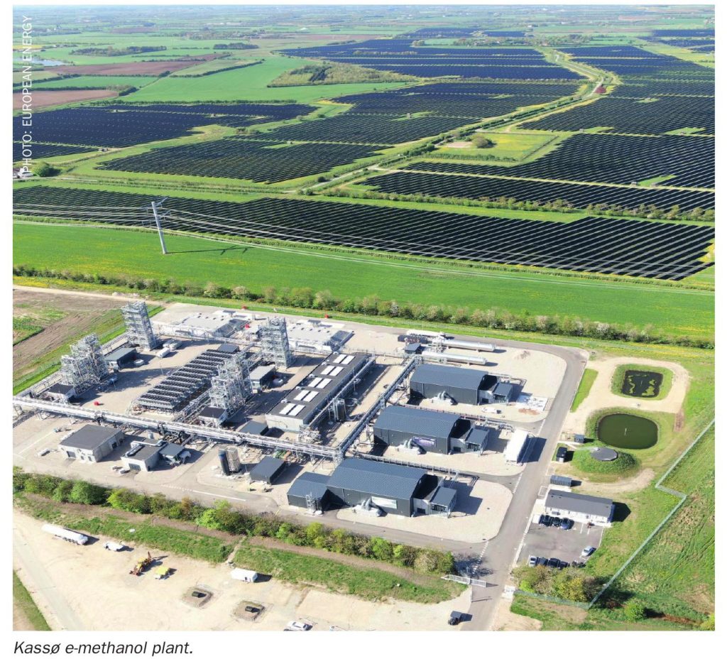
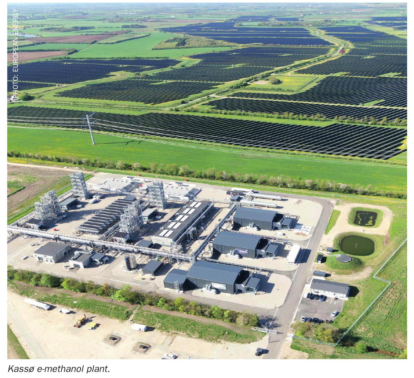
As demand for green methanol grows, the Kassø e-methanol plant in Aabenaa, Denmark represents a significant milestone as the first commercial-scale e-methanol production facility in operation with a nameplate capacity of 42,000 t/a.
The Kassø project, demonstrates industrial-scale conversion of renewable power and biogenic CO2 into e-methanol suitable for fuel and chemical applications. European Energy and Mitsui constructed the facility as a joint venture, integrating a 304 MW solar park with a Power-to-X (PtX) plant to supply marine and chemical markets. Construction of the Kassø e-methanol facility began in May 2023, marking one of the first commercial-scale Power-to-X investments in Europe. Following completion of the main process units, green hydrogen was produced for the first time in January 2025, and first raw e-methanol followed in March 2025, confirming the integrated operation of electrolysis, CO2 supply, and synthesis. At full operation, the plant is designed to produce up to 42,000 t/a of e-methanol.
Hydrogen is produced on site via 52 MW of electrolyser capacity, yielding approximately 6,000 t/a of green hydrogen, which is subsequently converted to e-methanol. Renewable electricity is supplied primarily from the collocated ~300 MW Kassø Solar Park, currently the largest solar park in the Nordic region, with grid connection used for balancing and operational flexibility. The carbon source consists of around 45,000 t/a of biogenic CO2, captured, purified, and liquefied at a nearby facility before being transported by road to the methanol plant. This locally sourced biogenic CO2 enables production of RFNBO-compliant e-methanol while anchoring the project within the regional bioenergy value chain. Surplus process heat from the methanol synthesis and auxiliary systems is exported to the local district-heating network, supplying approximately 3,300 households in the Aabenraa Municipality.
Process and plant description
The Kassø e-methanol plant is designed as an integrated Power-to-X facility with two parallel methanol production and distillation trains, supplied by common hydrogen and CO2 preparation units. The overall process configuration is illustrated in Fig. 1.
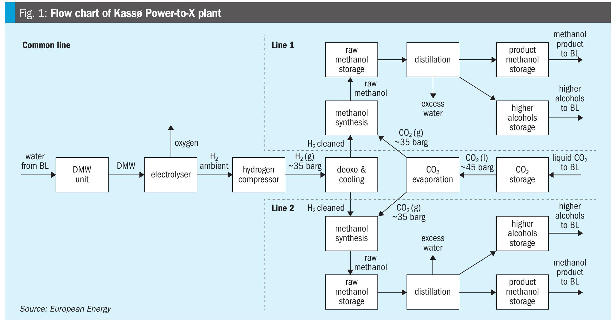
Hydrogen is generated on site by three Siemens electrolysis units operating at nearatmospheric pressure. The hydrogen stream is compressed to approximately 37 barg using five reciprocating compressors. A deoxygenation unit is installed downstream of the compression stage to remove trace amounts of oxygen from the hydrogen. No dedicated hydrogen drying unit is installed prior to the synthesis loop. Carbon dioxide is supplied to the plant in liquefied form by road transport and unloaded into two cryogenic CO2 storage tanks. From storage, the liquid CO2 is pumped to the required pressure and subsequently evaporated to provide gaseous CO2 for methanol synthesis. The conditioned hydrogen and CO2 streams are combined upstream of the synthesis section and distributed to the two parallel synthesis loops.
Each synthesis loop is based on a boiling-water reactor design, operating at approximately 35 barg and 240–250°C. Within the reactor, hydrogen and CO2 are converted to methanol over a copper-based catalyst. The reactor effluent is cooled, and the condensed methanol-water mixture is separated into a high-pressure separator, producing a crude methanol stream. Raw methanol from each synthesis train is routed to dedicated distillation units, where it is purified to meet IMPCA quality specifications. Purified product methanol is transferred to storage tanks and subsequently loaded onto trucks for transport to the nearby harbour, from which it is shipped to end users.
Plant operation and production capacity are adjusted in response to the availability and cost of electricity, allowing optimisation of hydrogen generation and methanol production under varying power market conditions.
Methanol synthesis catalyst system and activation
From a catalytic process perspective, one of the main challenges in CO2-to-methanol synthesis is the increased water content in the reaction system compared to conventional syngasbased methanol synthesis. The hydrogenation of CO2 to methanol is an exothermic reaction and, therefore, thermodynamically favoured at low reaction temperatures and high pressure. In the absence of carbon monoxide, however, higher water formation is unavoidable, creating more demanding conditions for the catalyst. Elevated water partial pressures can accelerate hydrothermal aging, leading to reduced catalyst activity and shortened lifetime. These effects place additional constraints on reactor design and operating conditions and require catalyst formulations specifically developed for CO2 rich synthesis gas compositions.
Green methanol production requires advanced technologies that reduce resource consumption and minimise waste. To address these requirements, the Kassø project employs a tailored methanol synthesis catalyst that demonstrates high activity under CO2 rich conditions, high methanol selectivity, and low by-product formation, including ethanol and methyl formate, thereby supporting stable operation and simplifying downstream purification.
The methanol synthesis catalyst used in this project is MegaMax™ 900, one of Clariant’s latest copper-zinc-alumina-based catalysts. Compared to earlier generations, the optimised copper loading and dispersion in MegaMax 900 increase the number of accessible active sites and the effective copper surface area. In CO2 tomethanol applications, this translates into high catalytic activity, excellent selectivity, and low deactivation rates, supporting an expected catalyst lifetime of at least three years under the operating conditions applied at Kassø.
Catalyst loading
The methanol synthesis reactors at Kassø are designed as inward radialflow steam-raising tubular reactors with the catalyst loaded on the shell side. This inherently limits physical access during catalyst loading. Achieving a uniform catalyst bulk density in both the radial and axial directions is therefore critical to ensure homogeneous gasflow distribution and stable reactor performance. To address these constraints, the loading concept was developed jointly with European Energy and a loading company, based on a detailed understanding of the reactor internals and loading geometry.
Prior to catalyst loading, an internal inspection of the reactor was carried out using a borescope to verify the condition and alignment of internals and to define an appropriate loading strategy. This preparatory step was essential to minimise the risk of catalyst damage and ensure consistent packing, given the access limitations.
Catalyst loading was performed through the central pipe in discrete batches. After each batch, the catalyst bed outage was measured both at the reactor centre and close to the catalyst basket wall to verify uniform radial distribution and confirm that the axial loading density remained consistent throughout the bed. Following the first loading batch, a video inspection was conducted to assess catalyst integrity, as the freefall height during loading exceeded seven meters. The absence of broken particles confirmed the high mechanical strength of the catalyst pellets. Based on the inspection results, minor adjustments to the loading procedure were implemented to maintain a stable and reproducible loading pattern for the remaining batches. Through this controlled and closely monitored loading procedure, a uniform bulk density of approximately 1,200 kg/m³ was achieved across the catalyst bed.
Catalyst activation
MegaMax 900 catalyst is supplied in its oxidised state, with copper present as copper oxide. Before the reactor can be put into operation, this copper oxide must be reduced to metallic copper, the active constituent for methanol synthesis. MegaMax 900 catalyst is reduced by passing a carrier gas through the catalyst and adding controlled amounts of hydrogen that reacts with copper oxide to form metallic copper and water, releasing heat according to the reaction:
CuO + H2 → Cu + H2O ∆H = –80.8 kJ/mol
Catalyst activation was performed using the plant’s recycle loop, consisting of the recycle compressor, the methanol synthesis reactor, and the high-pressure separator. Nitrogen served as the carrier gas, while hydrogen was introduced upstream of the recycle compressor from a pressurised tank. The hydrogen feed rate was controlled through a combination of supply pressure and valve opening.
During heating and throughout the reduction, carbon dioxide is released from the catalyst. To prevent its excessive accumulation in the recycle loop, a continuous purge was maintained at the highpressure separator. The purge rate depended on both the measured CO2 concentration at the reactor inlet and the amount of nitrogen required to maintain loop pressure. Without adequate CO2 control, elevated concentrations can significantly slow down the reduction process or, in extreme cases, cause irreversible catalyst damage.
In parallel, careful monitoring of hydrogen concentrations in the loop was required to avoid excessive accumulation, which could pose a risk of runaway reaction. For this purpose, Clariant’s proprietary gas analyser was used throughout the activation procedure to track H2 and CO2 concentrations at both the reactor inlet and outlet. Water condensed in the high-pressure separator was collected and quantified, providing a direct indication of the reduction progress.
During the activation campaign, three unplanned trips of the recycle compressor occurred. Due to the short response times, rapid stabilisation of operating conditions, and implementation of appropriate corrective measures, no adverse effects on catalyst reduction were observed. In particular, no CO2 or H2 accumulation or deviations from the intended activation trajectory occurred. Continuous on-site presence of Clariant personnel ensured immediate support and close coordination with the operating team throughout these events.
During the first 15–18 hours, nearly all injected hydrogen was consumed within the reactor. As reduction progressed, an early hydrogen breakthrough was observed, indicating a shift in the reduction behaviour. At this stage, the sampling frequency was increased to avoid hydrogen accumulation in the loop and to ensure stable operating conditions. Once the inlet and outlet H2 concentrations converged, the reduction neared completion.
In the final phase, hydrogen concentration and reactor temperature were increased to soak the catalyst, allowing heat and reducing agent to penetrate deeper into the pellets. After several hours of soaking, completion of the reduction was confirmed by stable gas-phase measurements and by the total amount of condensed water, which was consistent with the theoretical value expected for the full reduction of copper oxide.
Operational Performance
Following start-up, plant operation has been characterised by a high degree of variability, reflecting both the challenges of the commissioning phase and the power-driven nature of the facility. Frequent load changes, intermittent shutdowns, and a number of trips occurred, particularly during the early months of operation, limiting the availability of long, uninterrupted steadystate periods. Under these conditions, reactor and catalyst performance were evaluated using indicators that remain meaningful under dynamic operation rather than relying solely on extended timeonstream data.
Reactor performance was assessed based on reconciled operating data. Hydrogen flow to the synthesis loop was measured using a mass flow meter at the mixing point and independently verified through the electrical current consumed by the electrolyser units. Carbon dioxide flow was measured by a vortex flow meter at the mixing point and cross checked against measurements from the CO2 evaporation unit. This data reconciliation provided a consistent basis for evaluating synthesis performance across varying operating conditions.
Despite the operational variability, the synthesis loop has shown consistently strong performance from the beginning of operations. The reactor is operated at an outlet temperature of approximately 240°C and an actual pressure of 30–31 barg, which is lower than the original design pressure. This operating point indicates high intrinsic catalytic activity and reaction rates under the applied conditions.
Catalyst performance was further evaluated using the calculated approach to thermodynamic equilibrium. Throughout the observed operating period, the approach to equilibrium remained consistently in the lower range with no systematic increase over time despite frequent load changes and interruptions. The stability of this indicator suggests that the catalyst’s high activity was maintained under the prevailing dynamic operating regime.
Additional insights into catalyst activity were obtained during shutdown events. When the synthesis loop was stopped, the makeup gas flow was interrupted, but circulation was maintained. Under these conditions, loop pressure decreased to approximately 9 barg, indicating that methanol synthesis reactions continued to proceed at very low pressure. This behaviour provides qualitative confirmation of high intrinsic catalyst activity, even under strongly reduced thermodynamic driving force.
Loop stability during operation was reflected in the very low purge requirement. The purge gas flow was maintained at approximately 0.1 % of the total recirculating flow, indicating minimal formation of inert components and stable loop operation. This low purge requirement was sustained across varying loads and operating modes, highlighting the catalyst’s superior performance.
Overall plant performance improved significantly during the first six months of operation. The frequency of trips decreased over time, and the plant demonstrated increasing stability and reliability as operating experience was gained, and control strategies were refined. Throughout this period of dynamic operation, no adverse impact on catalyst performance was observed.
The results demonstrate that advanced methanol synthesis catalysts such as MegaMax 900, combined with comprehensive technical support during implementation and startup, are well-suited for emethanol applications. The experience gained at Kassø provides confidence that robust catalyst systems and close supplier-operator collaboration enable reliable and efficient operation of future largescale PowertoX methanol plants operating under similarly dynamic conditions.
Reference