Nitrogen+Syngas 399 Jan-Feb 2026
26 January 2026
Life management of reformer convection section tubing
ASSET INTEGRITY
Life management of reformer convection section tubing
The convection section of a syngas reformer is vulnerable to creep, corrosion, erosion, fretting and fouling which can cause deformation, local metal loss and failures that risk plant shutdown. Inspection access is limited, but solutions are available. Olivia Chung, Tim Haugen, and Charles Thomas of Quest Integrity discuss life management of the reformer convection section to reduce unplanned outages.
Overview of a reformer convection section
The reformer is frequently described as the heart of the syngas plant, consuming large amounts of energy to maintain the furnace temperature and drive the reforming process. To maximise efficiency, heat from the reforming reaction is captured and transferred to the convection section downstream of the reformer furnace. This section consists of several coils that recover heat from the flue gas via radiation and convection heat transfer. Fig. 1 shows an example arrangement of key processes that occur in a convection section.
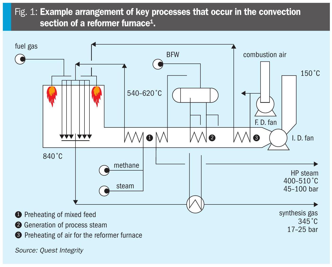
The flue gas temperature in the convection section can range from 1,000°C immediately downstream of the reformer furnace to 250°C toward the stack. This wide temperature range in the convection section enables multiple process streams to recover heat and improve thermal efficiency of the plant. The key process streams include:
- Preheating the mixed feed (methane and steam) for the catalyst tubes in the reformer furnace.
- Generating steam for use in other plant processes.
- Preheating the combustion air for the reformer furnace.
Materials of construction and damage mechanisms
A variety of metallic materials and coil/ header configurations are used to improve plant process and thermal efficiency, as well as optimise the mechanical integrity of the convection section tubes. From the range of services and operating temperatures encountered in the convection section of a reformer furnace, the materials of construction range from carbon and low alloy steel to creep strength enhanced ferritic (CSEF) steels and austenitic stainless steel tubes for superheater steam tubes and process mixed feed coils. The tubes and coils may be bare tubes or finned (to further optimise heat transfer), with various header-to-coil arrangements. The coils and tube bundles are often very tightly spaced within the convection section and header arrangements can similarly be complex.
There is also a range of life-limiting damage mechanisms for convection section coils that will vary depending on the process parameters. These include:
- Creep: Time-dependent deformation of materials that can lead to macro-cracking. This damage mechanism is very dependent on the temperature, with coils and superheater steam tubes located nearest to the reformer furnace being the most susceptible given the higher flue gas temperatures. A diametral change is typically observed before a rupture/leak occurs, as shown in Fig. 2.

- Corrosion: General and/or localised metal loss resulting from interaction with the process on the internal surface and/or flue gas on the external surface. Fig. 3 shows an example of localised metal loss of a convection section.

- Erosion.
- Fretting damage due to mechanical vibration.
- Internal and external fouling: Reduces process throughput and thermal efficiency.
Damage to convection section coils and tubes can also affect tube supports and the adjacent refractory. The failure of any coil in the convection section is likely to pre-empt a shutdown of the reformer.
Inspection challenges and solutions
There are known challenges with respect to the inspection of convection section coils and tubes, with limited access being the primary barrier. Raised surfaces, such as fins, on the convection section coils and tubes also present a challenge for external inspection. Furthermore, the presence of external and/or internal fouling can mask damage underneath. Compared with the catalyst tubes in the reformer furnace, many convection sections have limited inspection and are instead maintained using conservative life-cycle predictions based on operating conditions, tube metallurgy and feedstock type. In recent years, the industry has developed the following solutions to address these inspection challenges:
- External damage detection: High-pressure, low-volume robotic water cleaning methods such as those offered by IGS (Tube Tech) are highly effective for removing external fouling, particularly for finned tubes, before an external visual inspection by use of remote videoscope and/or cameras, where accessible.
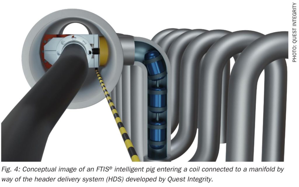
- Internal damage detection: Mechanical cleaning pigs remove internal fouling
- ahead of an ultrasonic inspection with an intelligent pig (e.g., FTIS® by Quest Integrity), which can detect radial deformation (e.g. bulging and out-of-roundness). The inspection data collected from FTIS® inspections can be used in a fitness-for-service (FFS) assessment.
- Header delivery system: Where possible, a header delivery system can be used to launch and receive the mechanical cleaning pig and intelligent pig. This patented solution, developed by Quest Integrity, is achieved by removing one flanged end of the manifold or header or by cutting one end cap, before inserting the delivery system (Fig. 4).

Application of engineering assessment approaches for integrity management
Engineering and condition assessment methodologies can be used to manage the integrity and service life of convection section coils. API 579-1/ASME FFS-1 “Fitness-for-Service” is a widely accepted standard that describes assessment approaches for determining the structural integrity of operating equipment containing identified flaws and/or damage2. The outcomes of an FFS assessment are that the equipment is safe to run as-is, remedial action is needed to remove the identified flaws and/or damage, or replacement of the operating equipment is required. Damage mechanisms covered in API 579-1/ASME FFS-1 include general metal loss, localised metal loss, dents, and creep.
For each damage mechanism, three levels of FFS assessment can be undertaken, with Level 1 representing a basic assessment that generally incorporates inspection data, design conditions, and published material properties. However, Level 1 assessments are intended to be used as an initial screening check for comparison with a defined limiting criterion as the results can be conservative. As a result, a Level 2 or Level 3 assessment can be undertaken to improve the output from a Level 1 assessment, as inputs such as the determination of actual material properties from destructive testing or the use of computational analysis methods (e.g., finite element analysis and/or computational fluid dynamics) to improve the applied loads can be refined. Where sampling of convection section tubes and coils is possible, destructive laboratory examination and materials testing can be undertaken to ascertain the metallurgical condition of the material. Materials testing can incorporate tensile testing, Charpy V-Notch impact testing, fracture toughness testing, creep rupture testing and/ or Omega creep testing, where appropriate and material permits. This information can be used as an input for a Level 2 or Level 3 FFS assessment, as previously noted.
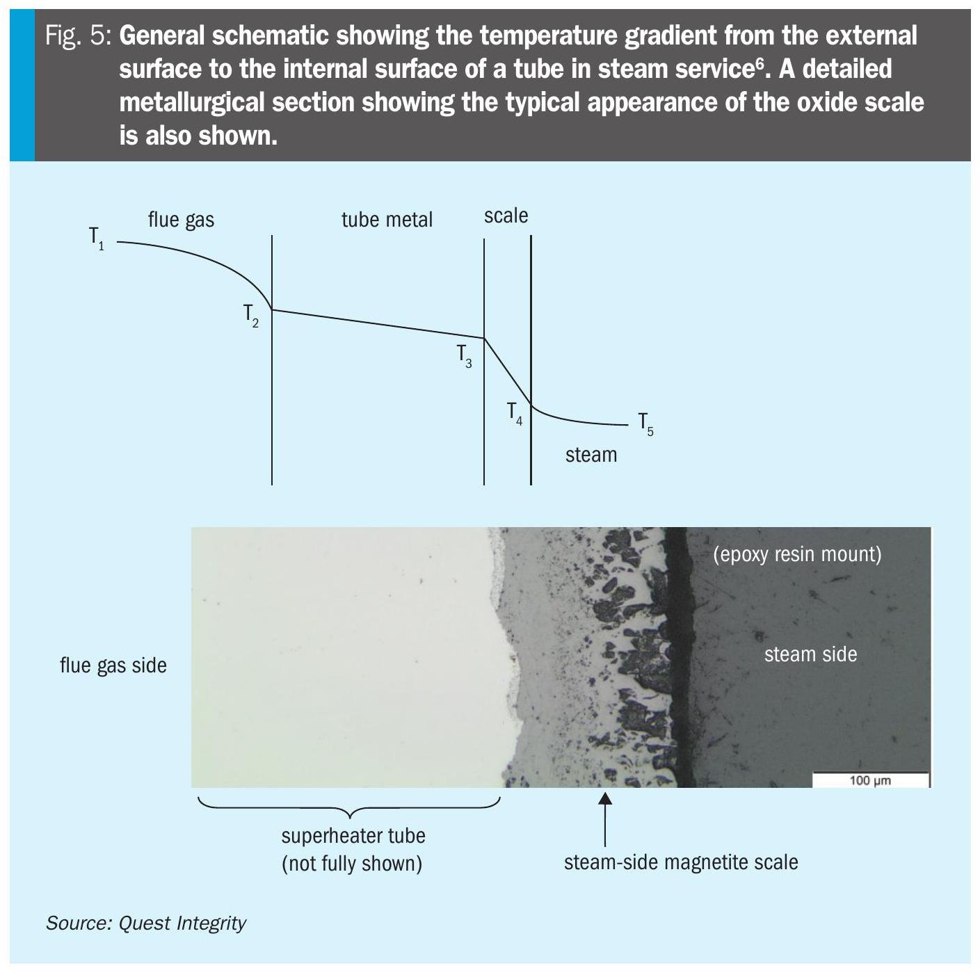
For coils and tubes operating in steam service, the oxide thickness-based life assessment can be used as an alternative approach to API 579-1/ASME FFS-1. This methodology utilises correlations developed by the Central Electricity Generating Board (CEGB) in the UK and the Electric Power Research Institute (EPRI) in the US to describe the oxidation kinetics for low alloy ferritic steels and some CSEF steels (namely 9Cr1Mo and 9Cr1MoV steels)3,4,5. The thickness of the steam-side magnetite scale provides an estimate of the tube metal temperature (Fig. 5), which is then used as an input for a creep remaining life assessment. This methodology has been widely adopted by power generation operators for managing the integrity of boiler and heat recovery steam generator (HRSG) tubes in subcritical and supercritical fossil-fuelled power plant and planning for tube replacements. This approach could also be adopted for assessing the creep remaining life of convection section coils and tubes operating in steam service, assuming that any heat flux, steam-side oxide thickness, wall thickness and material properties are known. If access permits, the steam-side oxide thickness and metal wall thickness could be obtained using ultrasonic methods. Alternatively, this information could be obtained by destructive laboratory examination, with any materials testing undertaken to provide the actual material properties for the creep life assessment.
Summary
Given the wide range of process services, materials of construction, and coil and tube arrangements that recover heat from the reformer furnace flue gas, the convection section of a reformer furnace remains a challenging asset for operators to manage. Although inspection access remains largely constrained, inspection solutions such as robotic water cleaning methods to remove external fouling for visual inspection and the use of adaptive header delivery systems to enable cleaning followed by intelligent pigging technologies to inspect the internal surfaces and monitor the wall thickness are available. Inspection data can be incorporated into an engineering assessment using standards such as API 579-1/ASME FFS-1 to understand the coil integrity. Furthermore, the oxide thickness-based life assessment for coils operating in steam service can also be adopted as an alternative methodology to determine the creep remaining life, where appropriate. This previously unobtainable information will improve understanding of the convection section condition and integrity, thereby helping operators plan periodic maintenance and bulk coil/tube replacements while mitigating unplanned outages from in-service failures.
References