Sulphur 421 Nov-Dec 2025
26 November 2025
Analysing COS and CS2 in a modern SRU
MONITORING AND CONTROL
Analysing COS and CS in a modern SRU
Maximising sulphur recovery in a modified Claus SRU/TGTU requires controlling and monitoring COS and CS2. Leveraging decades of monitoring experience, AMETEK Process Instruments discusses the formation, impact and monitoring of COS and CS2.
Rod Merz, Michael Gaura, Harry Burton, Nirav Patel (AMETEK Process Instruments)
For refineries, natural gas processing plants, coke producers and chemical plants, maximising the conversion efficiency of hydrogen sulphide (H2S) to elemental sulphur is a critical path to meeting modern emission standards. To achieve this, the modified Claus sulphur recovery unit (SRU) combined with an amine-based tail gas treatment unit (TGTU) is a common configuration with a proven track record in obtaining a high level (>99.9% and better) of sulphur recovery efficiency.
Both carbonyl sulphide (COS) and carbon disulphide (CS2 ) are well-known reactants formed in the initial thermal reaction stage of the SRU. These compounds have been identified as contributing to elevated sulphur (as SO2 primarily) emission levels. In a modified Claus SRU without tail gas treatment, it has been demonstrated in extreme cases that COS and CS2 formation can result in H2S conversion efficiency losses as high as 10%1,2. While extreme cases such as this are not the norm, any COS and CS2 that makes it past the SRU’s first converter stage ultimately end up as emissions. The addition of an amine-based TGTU provides a second opportunity to convert residual COS and CS2 from the SRU to further reduce these compounds before they are sent to an incinerator.
The measurement of COS and CS2 can provide valuable insights into the performance of both the SRU and the TGTU as well as explain increases in emissions when COS and CS2 levels are elevated due to abnormal operation of the SRU and TGTU.
AMETEK Process Instruments has a background of over 50 years in sulphur recovery and combined global sales of over 2400 analysers into modified Claus plants and amine-based tail gas treater units from which much of the content presented is based upon.
Modified Claus SRU and amine-based TGTU layout
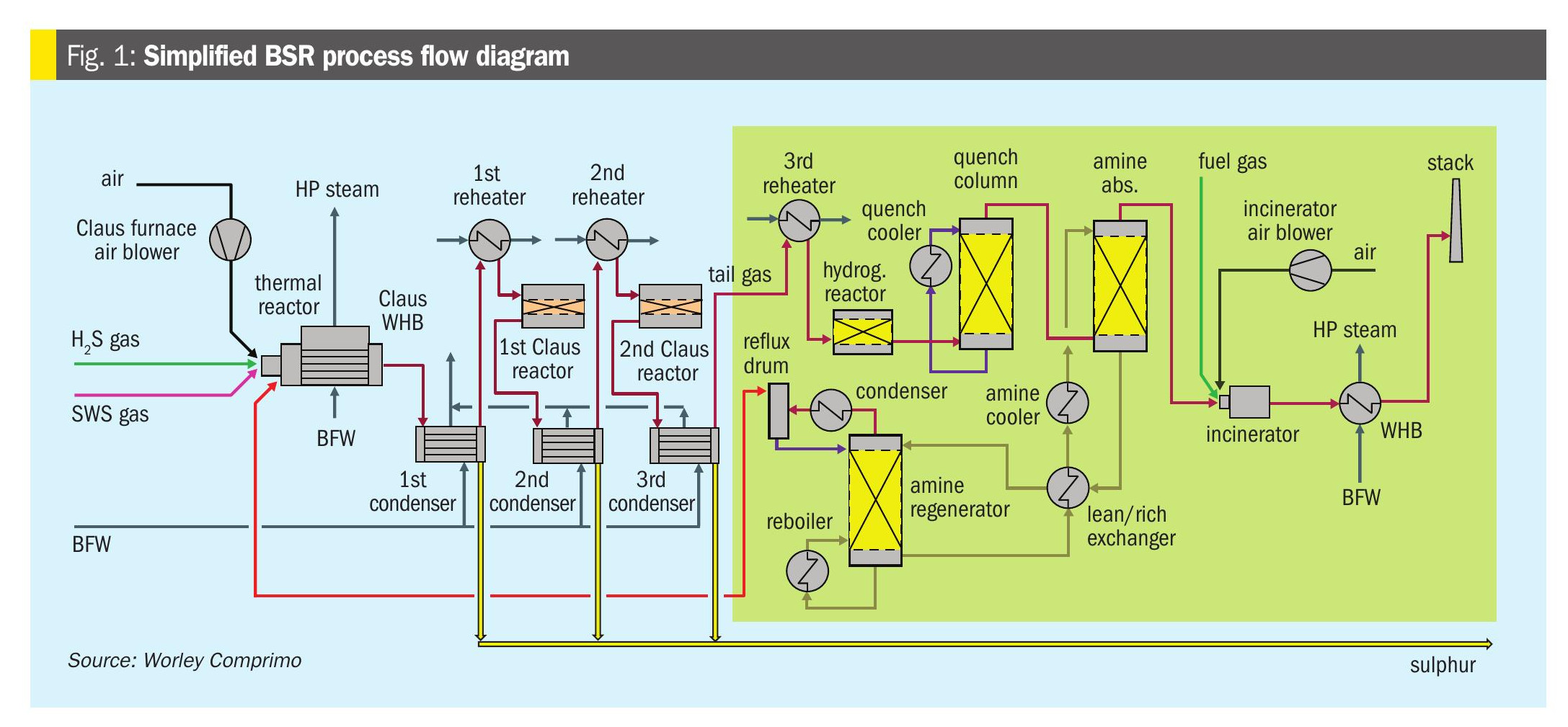
The modified Claus SRU illustrated in Fig. 1 consists of five essential components, the thermal reactor, a waste heat exchanger, an initial condenser, and then typically multiple stages of gas reheaters, catalytic beds and condenser segments. Amine-based TGTUs will also have a catalytic converter section that utilises a cobalt (Co) molybdenum (Mo) catalyst. It may also have a reducing gas generator (RGG) in front of it, or another means of supplying additional hydrogen (H2). The CoMo catalyst bed is typically followed by a quench tower with an amine absorber and amine regenerator section at the end. There are additional components, but these will not be relevant to the topic.
Modified Claus chemistry of COS and CS2 in the SRU
For both refineries and sour gas plants, acid gas feed streams contain several components other than H2S. Refineries will usually have an additional stream of sour water stripper gas (SWSG) added to the inlet of the SRU. In both cases, various hydrocarbons (HC), carbon dioxide (CO2 ), water (H2O), and ammonia (NH3 ) are part of the acid gas and SWSG feeds into the reaction furnace. These additional components are involved in many side reactions during the thermal reactor stage of the SRU.
Most of the important chemistry for the modified Claus reaction occurs in the thermal reactor stage where the goal is to utilise the modified Claus reaction and convert 1/3 of the H2S to SO2 in the thermal reactor stage to further react again to produce elemental sulphur (equation 1). The reaction between SO2 and H2S to form sulphur is equilibrium limited and to move the reaction forward, the sulphur produced must be removed.
The first condenser removes the produced sulphur allowing the same reaction to move forward again in the first and subsequent catalyst beds; however, there are many side reactions that occur as well. Much of the formation of COS and CS2 also occurs in the thermal reactor where CO2 and HCs are participants in these side reactions.
Equations 2 and 3 show the initial formation of CO from CO2. The CO is then converted to COS by reacting with the elemental sulphur produced as part of the Claus reaction.
Equation 4 illustrates the formation of CS2 from sulphur reacting with methane, although any other hydrocarbon species present can be substituted for methane in the reaction.![]()
After the formation of COS and CS2 in the thermal reactor, the SRU first converter bed is a significant opportunity to have these compounds undergo hydrolysis as shown in equations 5 and 6.
These hydrolysis reactions are favoured by higher temperatures in the first converter bed which is why the first converter bed is typically operated at a higher temperature than subsequent converter beds1,2.
Once COS and CS2 make it past the first converter bed, the last significant line of defence is the CoMo catalyst bed in the TGTU. The CoMo catalyst bed will allow a final opportunity for the hydrolysis reactions shown in equations 5 and 6. After the CoMo catalyst bed, any remaining COS and CS2 will end up in the incinerator and contribute to the plant’s emissions.
Measurement opportunities for COS and CS2 in the SRU
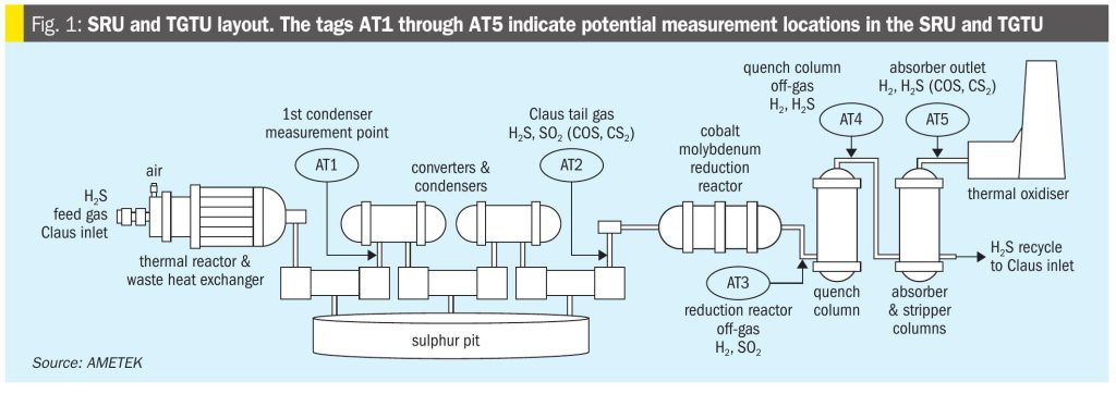
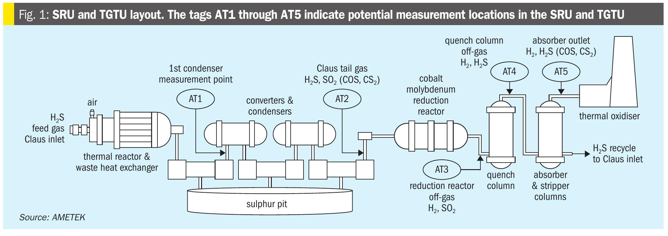
There are five potential locations where COS and CS2 can be measured in an SRU with an amine-based TGTU:
- the initial thermal reaction products found at the outlet of the first condenser (AT1 in Fig. 1);
- the post SRU remaining gas constituents measured at the outlet of the final condenser (AT2);
- the reaction products exiting the TGTU’s cobalt molybdenum reduction reactor with a measurement point in front of the quench tower (AT3);
- the quench tower outlet (AT4);
- the remaining products exiting the top of the TGTU absorber (AT5).
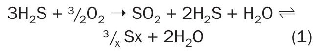
While the possibility exists to measure COS and CS2 after the SRU first condenser (AT1), the spectroscopic interference from concentrations of sulphur vapour, H2S and SO2 are substantial. Fig. 2 shows an example of the spectroscopic interferences at typical concentrations found after the first condenser.
This location would normally be considered a compromised sample point with high concentrations of sulphur vapour still present that can easily overwhelm a sample conditioning system under adverse conditions. Also, the hydrolysis reactions that take place in the first converter bed have not occurred, so the only information obtained will be an indication what has occurred in the thermal reactor regarding COS and CS2 formation. With little to no economic or functional gain to be had from this information, it has not been requested by industry.
The first converter bed does most of the work in performing the hydrolysis reaction for COS and CS2. It is operated at elevated temperatures to facilitate the reaction in equations 5 and 6 and maximise the hydrolysis reaction for COS and CS21,2. The addition of a layer of titania catalyst in the first converter may also be used to maximise the conversion of COS and CS2. Subsequent converters are operated at lower temperatures to maximise the Claus reaction and have a significantly smaller hydrolysis conversion rate. A measurement for COS and CS2 is possible after the first converter but the spectroscopic limitations for minimum detectable levels will still be worse than the measurement at the final condenser due to elevated H2S and SO2 compared to the final condenser location. The COS and CS2 are not expected to appreciably change after the first converter, so waiting to make the measurement after the final condenser makes more sense if there is a useful reason for the measurement at this point.
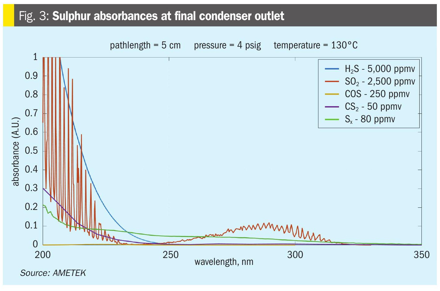
The SRU final condenser’s air demand analyser sample location (AT2) is the only effective place in the SRU where COS and CS2 measurements can be made. As such, this has traditionally been the location where any measurement of COS and CS2 is made. H2S, SO2, and sulphur vapour are at their lowest concentrations in the Claus unit at this point. While they will still provide some spectroscopic interference with the measurement of COS and CS2, this is the only potentially useful location in the Claus unit. The COS and CS2 measurements in this location are typically used to determine a loss in catalyst activity in the first converter bed. Measurements here have also been used to indicate significant variations of CO2 or hydrocarbons in the SRU feed gas concentrations that have passed through the thermal reactor and modified Claus unit. For the former, proper temperature profiling will give a good indication of catalyst activity in the first converter bed. For the latter, a feed forward analyser will be much more useful in dealing with changes in the SRU feed gas HC content. It should be noted that in situations where co-firing with natural gas is utilised, elevated levels of COS and CS2 will also be noticed; however, they should not fluctuate significantly over the co-firing period unless other events as mentioned above are occurring. There is little during SRU operation that can be done for significant changes in CO2 content in the acid gas feed that leads to higher COS formation other than to examine the upstream processes feeding the SRU.
As shown in Fig. 3, the interference from the remaining H2S and SO2 content in the tail gas can still result in a decrease in sensitivity for the COS and CS2 measurement. At this point, the noise floor for COS can be in the order of 200 ppm to 500 ppm depending on the final H2S and SO2 concentration. At levels of 5,000 ppm and 2,500 ppm for the H2S and SO2 respectively, this level of noise compromises the value of the measurement.
There are three opportunities to measure COS and CS2 within the TGTU:
- the quench tower inlet (AT3);
- the quench tower outlet (AT4);
- and the absorber (stripper) outlet (AT5).
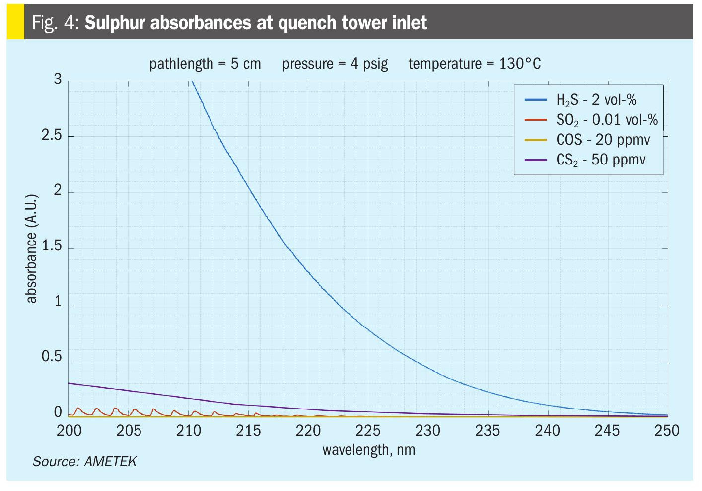
At the quench tower inlet (AT3), there is a significant reduction in COS and CS2 concentrations from the hydrolysis reaction in the CoMo catalyst bed. At the same time there is an increase in H2S with nearly all the SO2 having been converted to H2S.
COS and CS2 will be at their lowest concentrations in this location and H2S interference will be even more exaggerated compared to the final condenser measurement point (Fig. 4). In addition, the gas stream will have an elevated temperature. Any gas analyser installed at this location must have the ability to keep the sample in a gas phase, as any liquid formation would damage the analyser. Although some users have attempted to use sample coolers or chillers in this location, these tend to require more maintenance than the value any measurement would provide. From Ametek’s experience, the only measurements that are done at the quench inlet are for hydrogen (H2) and SO2. Any indication of residual SO2 will mean that the CoMo catalyst bed is not functioning properly and amine damage will occur. Hydrogen can be measured at any point after the CoMo catalyst bed, so unless the SO2 measurement is needed, it is best to measure H2 after the quench tower.
Measuring COS and CS2 at the quench tower outlet (AT4) would require much less sample conditioning, as the sample is now cooled, and any liquids or particulates should be removed and no longer present.
Unfortunately, the concentration of H2S is still expected to be within a range of 0.5 to 5%, once again, resulting in the same spectral interference on the measurement of COS and CS2 as found at the quench inlet.
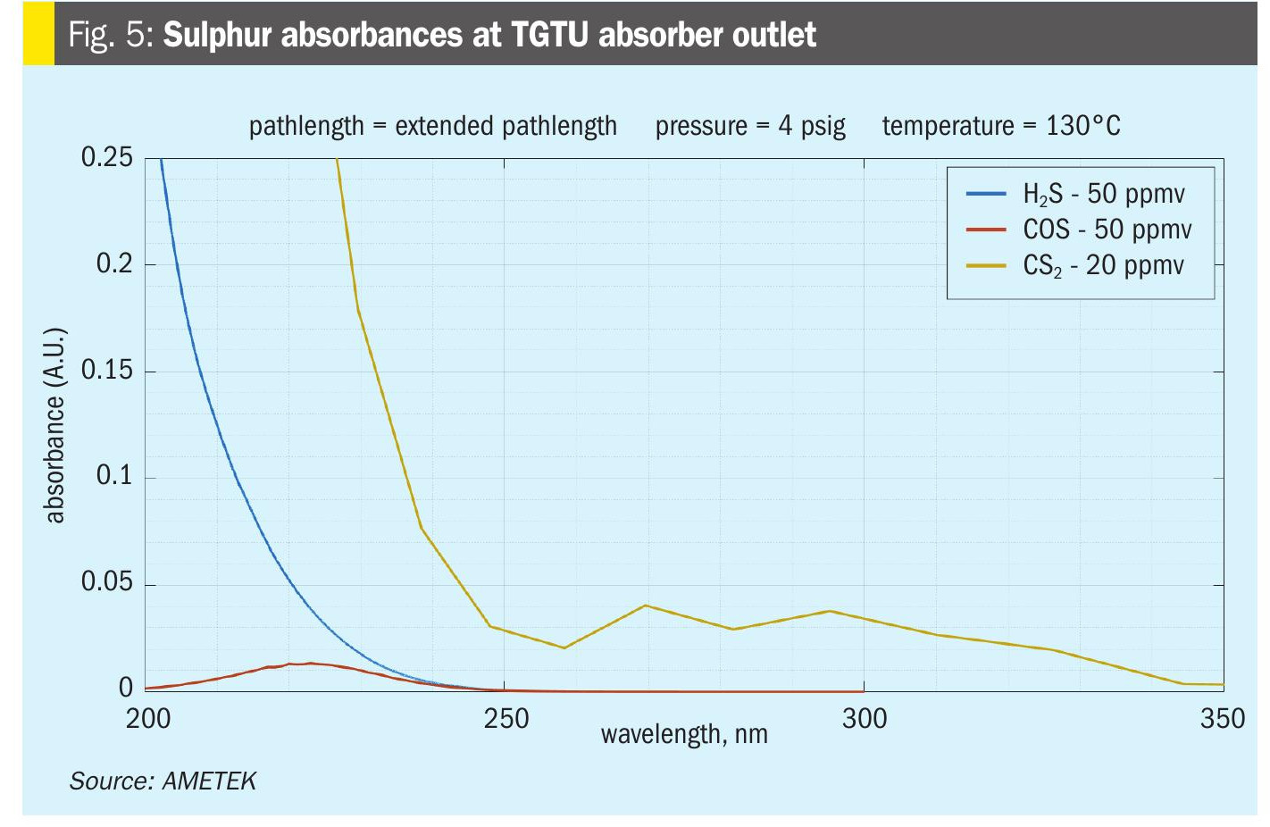
Which brings us to the final measurement point for COS and CS2; the measurement after the TGTU amine scrubber (AT5). This is the ideal location, as the sample will contain low ppm amounts of H2S with no SO2 or sulphur vapour. Here you will see the maximum resolution of the COS and CS2 measurements in the SRU and TGTU.
At this location the measurement COS, CS2 and H2S will directly indicate what is going to the incinerator or thermal oxidiser and end up as emissions (Fig. 5). These values should directly correlate to the emission measurements with the caveat that there may be other streams also going to the incinerator such as the sulphur pit gas sweep or other process streams that can increase the final SO2 measurements if the incinerator is shared with other operating units. As mentioned above, H2 can also be measured here as well since the concentration will not change downstream of the CoMo catalyst bed.
Summary
Measuring COS and CS2 in a modified Claus SRU/TGTU can provide useful information for determining the conversion activity of the first converter bed, the efficacy of the CoMo catalyst bed, and provide an indication of what the plants emissions will be; however, there are also limitations based on the measurement point location and the spectroscopic interferences observed from H2S, SO2, and sulphur vapour concentrations. Unless there is a specific need, the favoured location for the best resolution is at the absorber outlet (AT5). Any significant changes in the measurement of COS and CS2 here typically only have a few potential causes, feedstock gas composition changes, catalyst bed temperature changes, or catalyst activity changes.
References