Nitrogen+Syngas 397 Sep-Oct 2025
11 September 2025
Benfield CO2 revamp success: Strategic lessons and outcomes
AMMONIA PLANT REVAMP
Benfield CO2 revamp success: Strategic lessons and outcomes
VK Arora of Kinetics Process Improvements, Inc. (KPI, Houston) describes the systematic revamp of a Benfield CO2 removal unit at a high-throughput ammonia plant, emphasising simulation-driven diagnostics and customised engineering solutions. The initiative was prompted by persistent operational challenges, including excessive steam consumption, elevated CO2 slippage, and ongoing mechanical degradation.
The Benfield process remains widely used for CO2 removal in ammonia, refining, and petrochemical plants. However, many of these legacy units now operate under significantly higher loads than originally designed for, resulting in chronic performance degradation. Common challenges include deteriorating hydraulics in absorbers and strippers, increased CO2 breakthrough, solvent carryover, and rising steam consumption – all of which undermine plant efficiency, emissions compliance, and operational reliability.
This article discusses the systematic revamp of a Benfield unit (Act-1) at an ammonia facility operating at nearly 140% of its original design capacity due to multiple plant expansions. Previous incremental upgrades – such as packing replacements, higher circulation rates, and added ejectors – provided only temporary relief. Core issues persisted, including high CO2 slippage (up to 4,200 ppmv), elevated inerts in the synthesis loop, high LP steam demand, and reduced ammonia conversion efficiency. These inefficiencies led to incremental losses in ammonia and urea production and accelerated mechanical deterioration in some critical equipment.
Original design and expansion
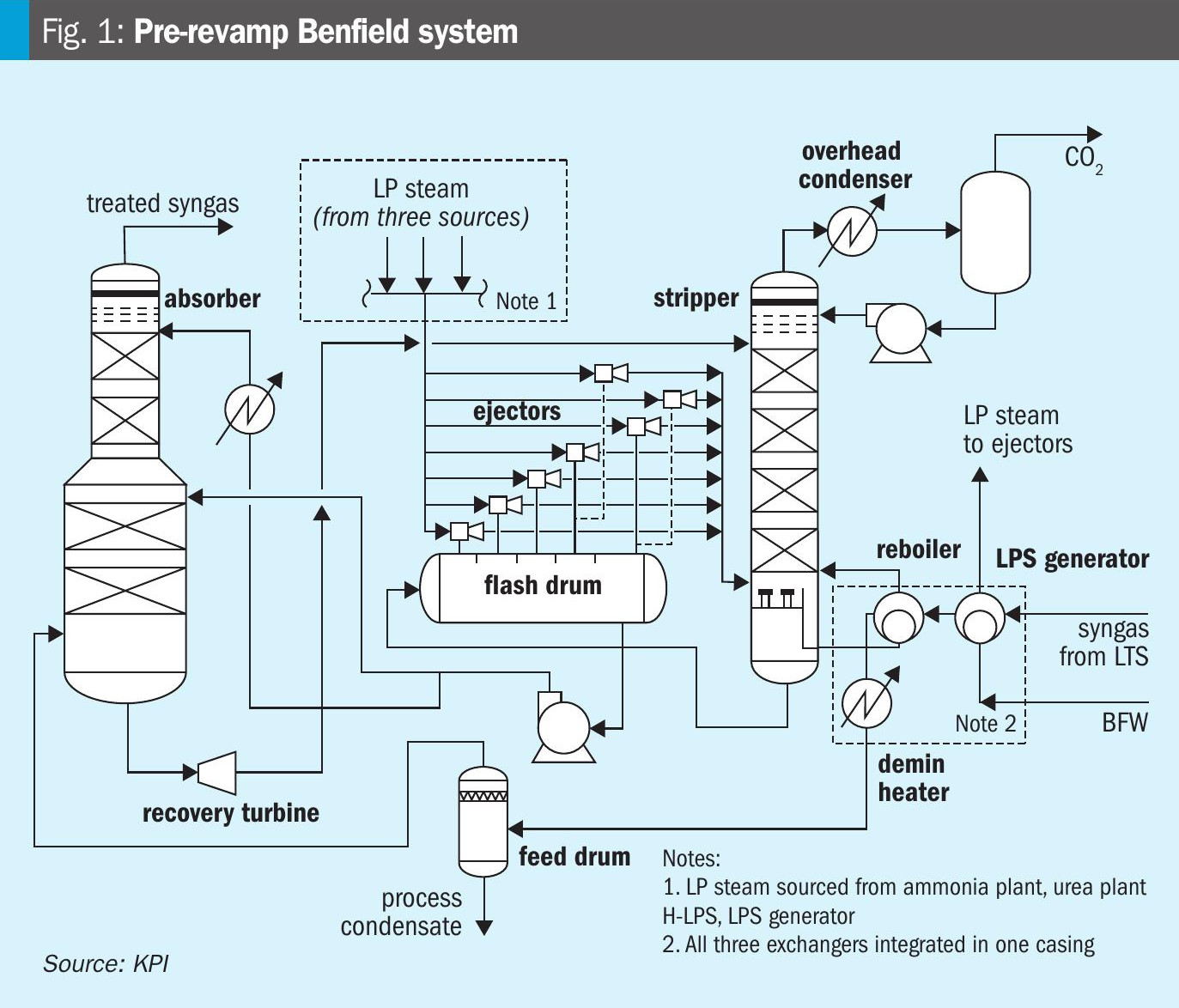
The ammonia plant was originally commissioned in 1992 with a nameplate capacity of 1,500 t/d. Subsequent capacity upgrades in 1997 and 2009 increased the plant’s output to 2,125 t/d. However, the Benfield CO2 removal system was not proportionally expanded during these debottlenecking efforts and underwent only limited modifications, as summarised below. The configuration of the Benfield system, as modified during the 1997 and 2009 expansions, is shown in Fig. 1.
Prior modifications
To accommodate the increased load from the 1997 and 2009 capacity expansions, several incremental modifications were implemented on the Benfield CO2 removal system:
- Replacement of random packing in the absorber with high-performance IMTP packing to mitigate flooding
- Addition of supplementary ejectors on the 4th and 5th compartments of the flash drum
- Installation of chevron trays in the stripper top section to reduce water and solvent carryover
- Upgrade of the overhead condenser and reflux drum system in the stripper
- Enhancements to the CO2 overhead knockout vessel
- Increase in Benfield solution circulation rate by ~17%
- Increase in potassium carbonate (~7%) and activator (~50%) concentrations
- Increase in LP steam injection to the stripper and ejectors.
These incremental changes proved insufficient, as system performance continued to deteriorate under elevated throughput conditions.
Pre-revamp operating challenges
Despite the incremental modifications introduced during the 1997 and 2009 capacity expansions, the Benfield CO2 removal system continued to experience persistent and interlinked challenges that constrained plant throughput, energy efficiency, and overall reliability:
High CO2 slippage (4200 ppmv, max), significantly above the original design limit of 1,000 ppmv. This elevated synthesis loop inerts, increases purge rates, and reduces ammonia conversion efficiency, ultimately impacting downstream urea production potential.
- Frequent pressure drop excursions and near-flooding in the absorber and stripper, reflecting severe hydraulic constraints and poor vapour-liquid distribution that undermined system stability.
- Excessive LP steam consumption, resulting in:
- Overfiring of auxiliary boilers
- Steam venting in the downstream urea unit
- Elevated cooling water and demineralised water demand
- Inefficient deaerator operation and increased operating costs
- Feed separator overload from elevated feed temperatures and rates, which led to solvent carryover and subsequent downstream fouling.
- Undersized flash drum and declining ejector efficiency, exacerbating hydraulic limitations and negatively impacting stripping performance.
- Restricted flow and thermal inefficiencies in the stripper reboiler circuit, worsened by degraded heat-transfer surfaces.
- Mechanical degradation of critical equipment – including flash drums, ejectors, reboilers, and associated internals – compromised system reliability and drove up maintenance frequency.
Collectively, these shortcomings resulted in unstable operation, elevated energy consumption, and reduced ammonia production efficiency, placing significant strain on downstream units and limiting the plant’s ability to achieve production targets consistently.
Revamp approach
To address persistent hydraulic, thermal, and reliability challenges, KPI executed a structured two-phase revamp methodology – developed in close collaboration with the end user – combining rigorous process modelling of the complete Benfield system with pragmatic, cost-effective engineering solutions. Phases 1 and 2 were completed by KPI in 2020, with full implementation and start-up successfully delivered by an EPC firm in mid-2022.
Phase 1
Phase 1 comprised simulation, performance modelling, and an integrated system assessment. KPI developed validated process simulation models that reasonably captured actual plant behaviour. These models enabled detailed scenario analysis, allowing precise bottleneck identification and quantification of operational limitations. A comprehensive assessment of column hydraulics, thermal performance, process integration, and mechanical adequacy was conducted for all major equipment: absorber, stripper, flash drum, ejectors, and reboiler, etc. Cost-benefit analyses were performed for multiple revamp options, incorporating vendor inputs for budgetary estimates and assessing implementation feasibility within plant layout constraints. Results were jointly reviewed with the end user, leading to the selection of the most technically and economically viable options and providing a robust, evidence-based foundation or Phase 2 PDP engineering.
Phase 2
Phase 2 comprised revamp engineering and the process design package (PDP). Based on Phase 1 outcomes, KPI prepared a comprehensive PDP for modified and new components, including:
• Flash drum sizing and configuration
• Process specifications for ejectors, reboiler, and column internals
• Operational adjustments to ensure stable performance at the expanded load
Phase 1 findings directly guided the revamp scope, equipment selection, and budgetary estimate – ensuring well-informed, reliable and smooth execution. Following the PDP, the end user engaged an EPC contractor for detailed engineering, procurement, and installation, culminating in a successful system startup in mid-2022.
Plant data versus simulation
The entire Benfield system was rigorously simulated using actual plant data and furnished design inputs, including the specific packings installed in the absorber and stripper columns. The simulation demonstrated good alignment with plant performance, as summarised in Table 1.
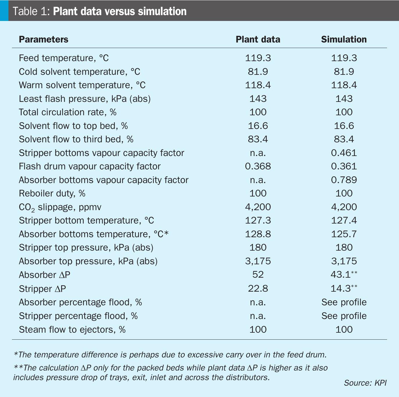
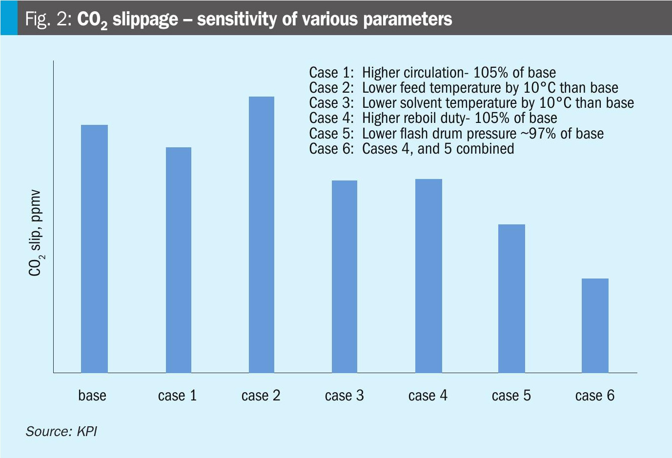
The validated model was subsequently used to evaluate improvement options, including a parametric study, with key results summarised in Fig. 2
Key findings
Based on the Phase 1 study conducted under base (normal) operating conditions, the following items were identified:
Overall equipment loading
Nearly all major equipment in the Benfield CO2 removal system had operated at or above original design limits. Hydraulic constraints had been especially pronounced in the absorber and stripper columns, adversely affecting vapour-liquid distribution, column efficiency, and overall system performance.
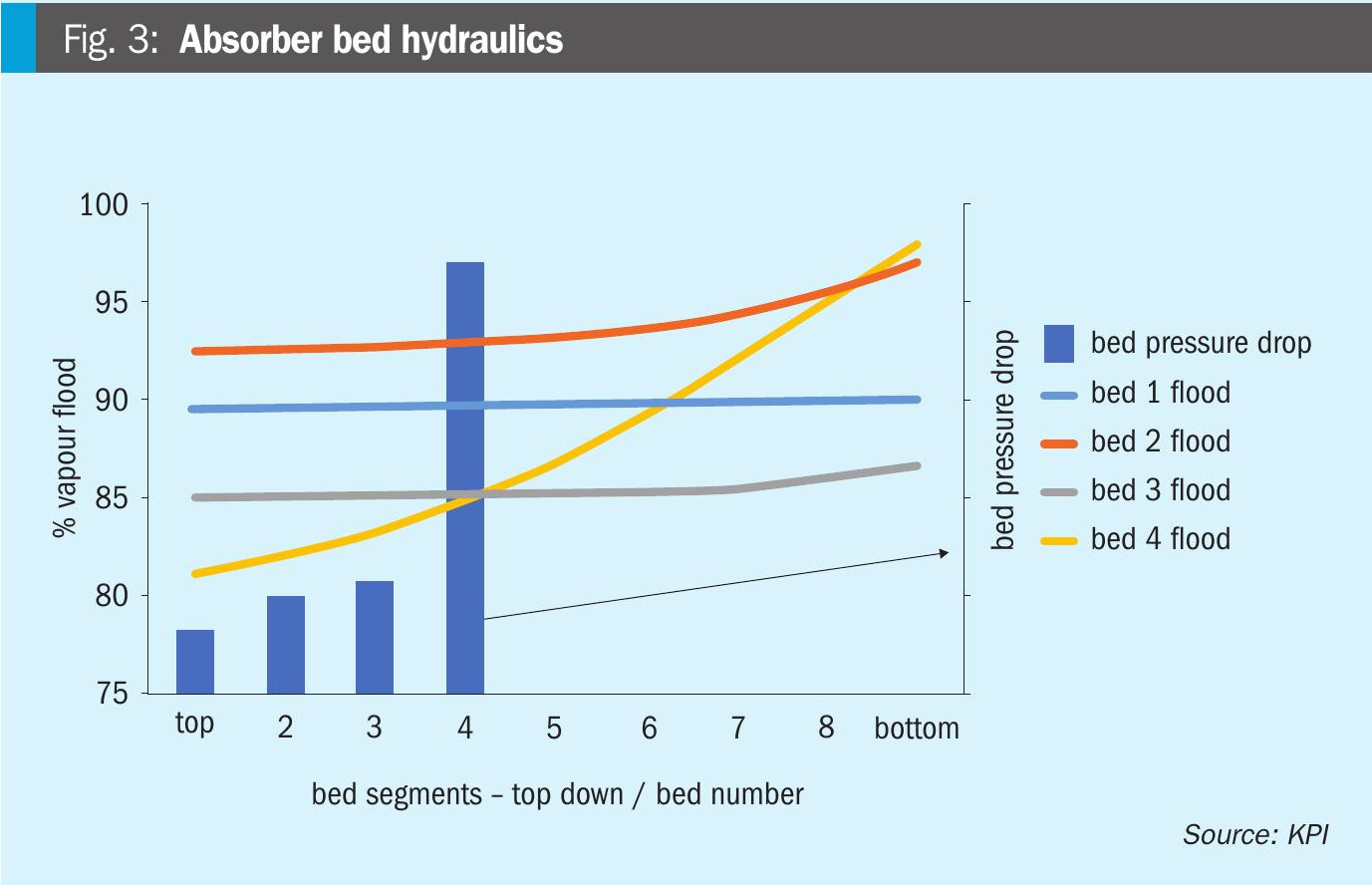
Absorber column
Flooding conditions: Fig. 3 indicates that Beds 2 and 4 were operating close to their hydraulic limits (at nearly 98% capacity) placing them at risk of incipient flooding.
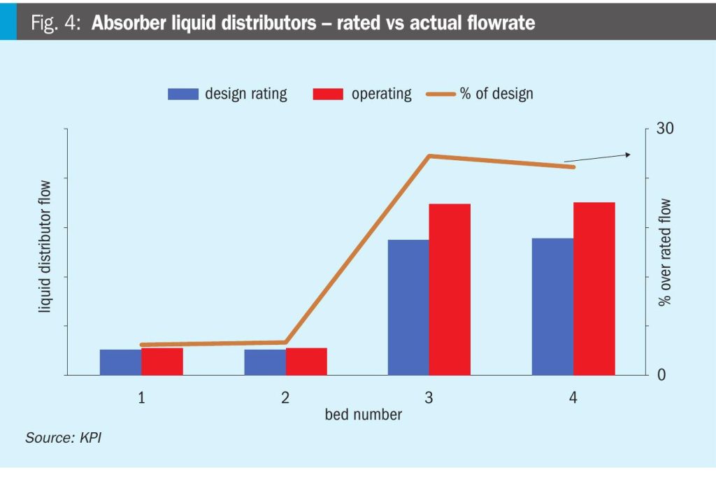
Liquid distributors: The lower two bed distributors had been significantly under-rated and likely overflowing, reducing column efficiency. The upper two distributors, though closer to rated capacity, had poor designs with low drip density and inadequate liquid distribution. Fig. 4 indicates that the lower liquid distributors operated at over 125% of their rated capacity, while the upper distributors were nearing their maximum design limits).

Vapour distribution: Excessive vapour velocity through the feed nozzle into Bed 4 had caused vapour maldistribution. A vapour distributor had been required; two installation options had been evaluated:
- Hot-work installation inside the column wall during TAR – technically preferred but outage-dependent.
- External installation by shortening and raising Bed 4 by ~1 m – less desirable as it eliminated future lower manway access.
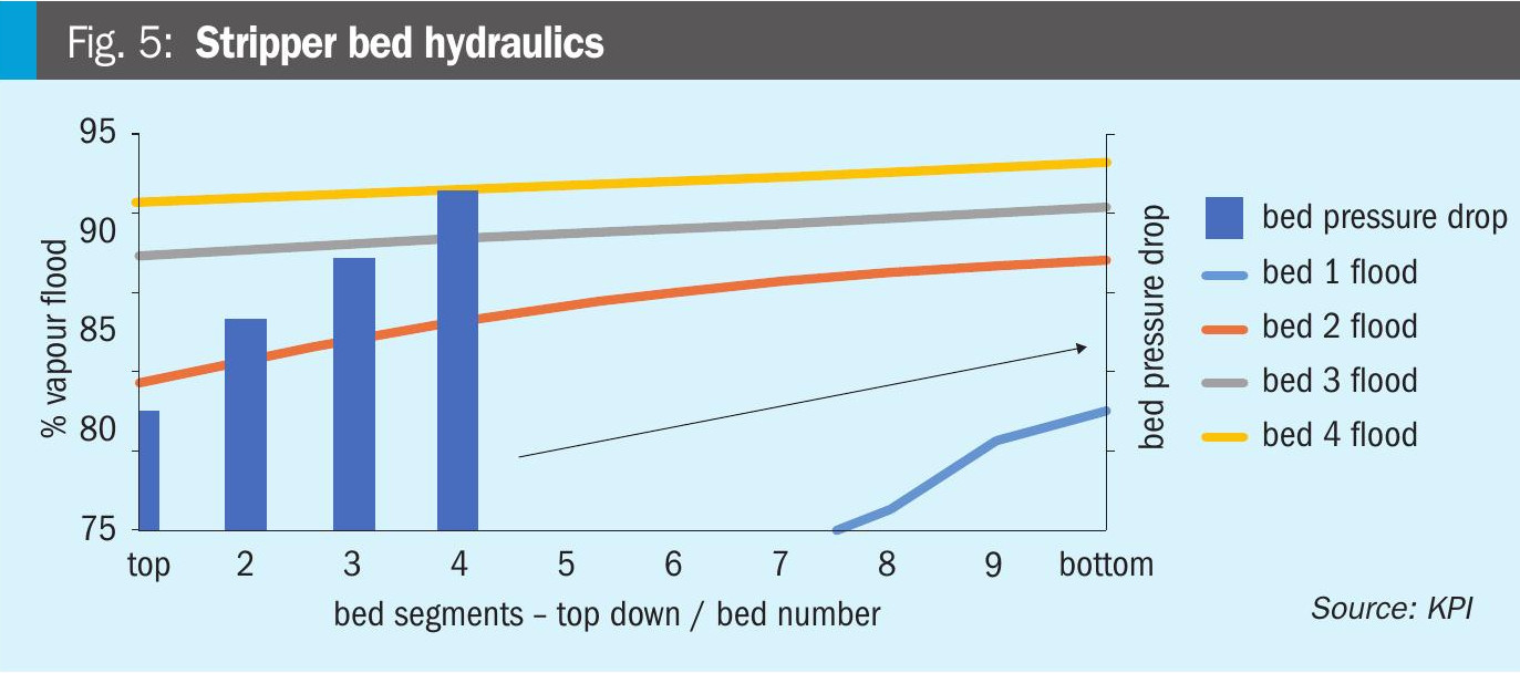
Stripper column
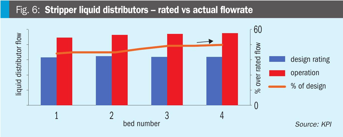
Flooding conditions: Bed 4 had operated at ~94% of flood capacity (Fig. 5).
Liquid distributors: As shown in Fig. 6, all four liquid distributors operated above 140% of their rated capacity, resulting in poor flow distribution and degraded performance.
Vapour distribution: As with the absorber, two vapour distributors had been recommended; feasibility of turnaround hot-work installation needed review.
Reboiler circuit: Liquid head to the reboiler could have been increased by modifying the bottom chimney tray collector box – hot work required during turnaround.
Wash trays: Likely operated in the spray regime due to low liquid rates, risking carryover. Cold condensate makeup had been redirected from the reboiler vapour line to the wash trays to improve liquid loading.
Packing evaluation
To address hydraulic limitations and reduce CO2 slippage, KPI conducted an extensive, independent evaluation of multiple packing configurations (summarised in Tables 2 and 3) for both the absorber and stripper columns. These assessments were performed using KPI’s validated Ben-field simulation model.
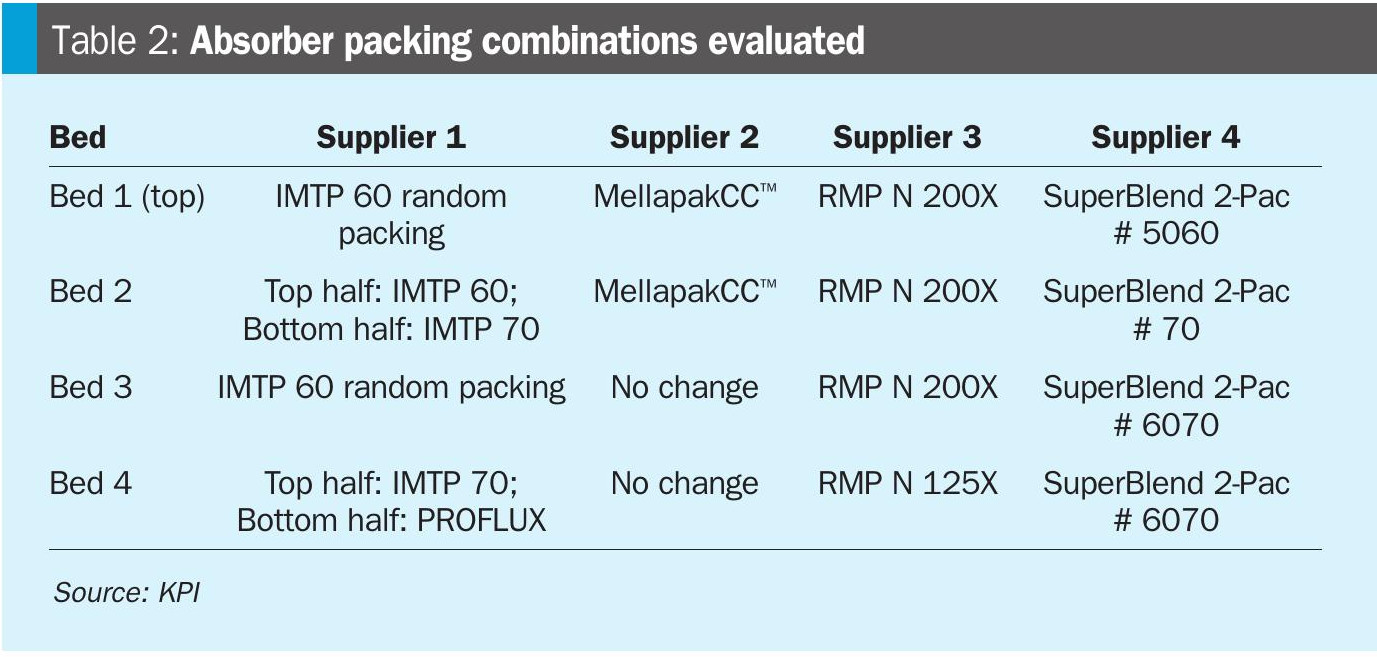
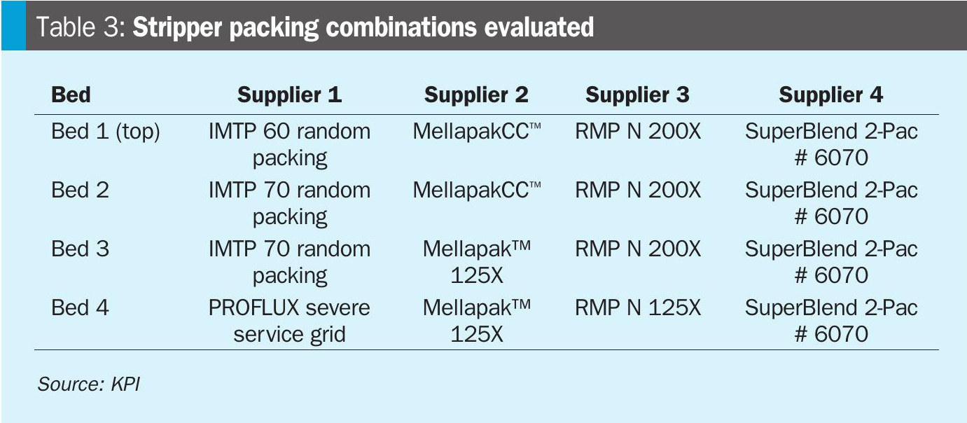
Based on simulation results and performance trade-offs, the evaluation recommended retaining the existing packings and deferring any replacement decisions until after the installation and performance validation of upgraded vapour and liquid distributors in both columns.
It was observed that the latest 4th-generation random packings demonstrated improved hydraulic characteristics but led to higher CO2 slippage while structured packings offered potential enhancements in both hydraulic performance and CO2 removal efficiency; however, their behaviour under high liquid load conditions remained uncertain, with limited full-scale commercial validation.
Flash drum and ejector system evaluation
Existing system: The flash drum had exhibited signs of aging (cracks in internals and welds) and several ejectors had shown wear and declining efficiency. Both had been scheduled for replacement during the next turnaround.
The existing drum was significantly undersized, offering insufficient vapour disengagement and inadequate residence time. A new drum, approximately 160% larger, was designed while retaining the original five-compartment layout to minimise piping modifications.
New ejector configuration: One ejector was designated per compartment, designed to operate under the existing low-pressure (LP) steam conditions. A detailed sensitivity analysis was performed to evaluate the influence of steam pressure and degree of superheat. The impact of these parameters on relative steam consumption by the ejectors was evaluated, as shown in Figs 7 and 8.
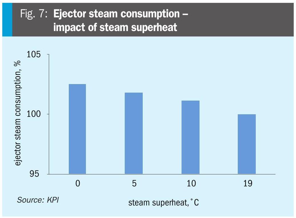
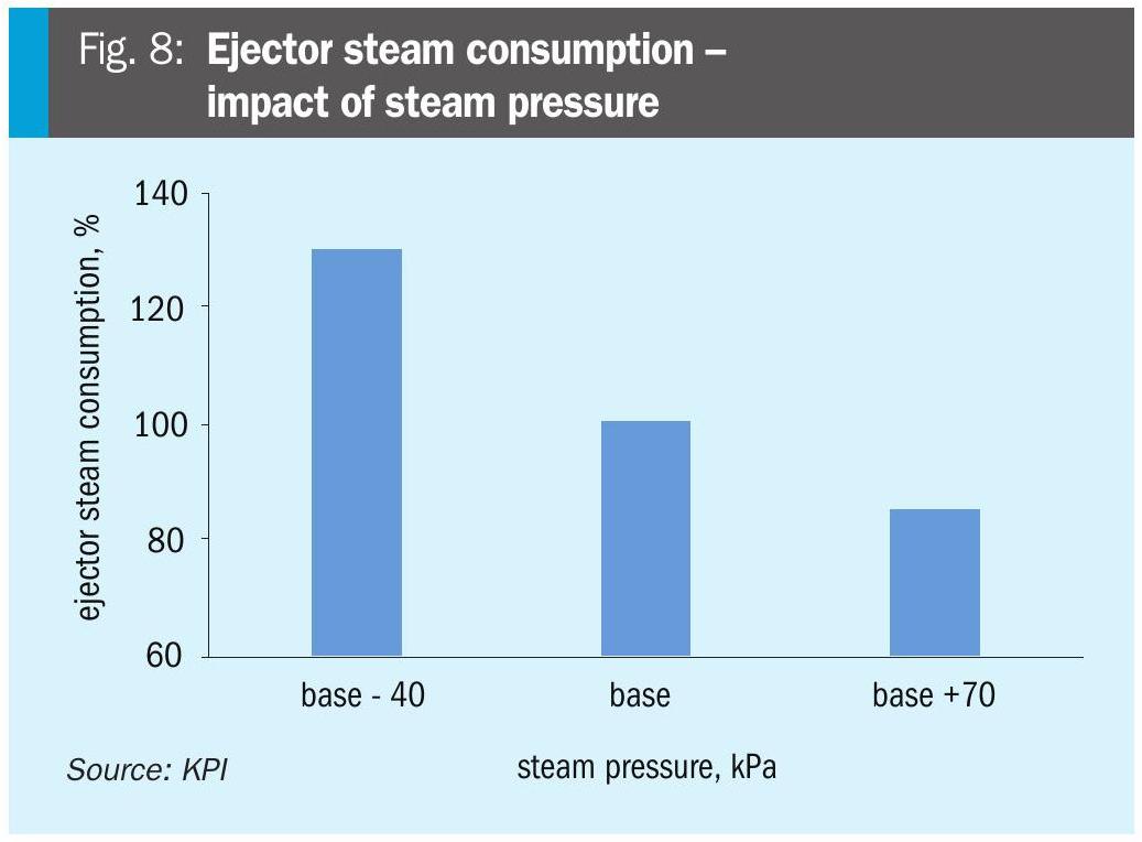
A slightly higher pressure greatly helps to reduce the steam consumption, whereas higher steam superheat is much less sensitive to the steam consumption.
Stripper reboiler replacement
Significant tube wall thinning in the existing reboiler had raised serious reliability and mechanical integrity concerns. A new design higher-duty replacement reboiler was engineered to increase the CO2 stripping capacity and improve the thermosiphon circulation while remaining within the existing space and piping constraints. A longer tube bundle was selected to fit the existing footprint without requiring layout modifications.
The new design provided operational benefits including:
- The reduced steam consumption relieved the auxiliary boiler load and contributed to lower greenhouse gas (GHG) emissions.
- A lower heat load on the demineralised water heater improved deaerator stability and performance.
Recovery turbine
The existing turbine was already operating at full capacity with the largest impeller installed. While replacing it could have enabled recovery of approximately 225 kW of additional power, doing so would have required major hardware modifications, including pump relocation. An economic evaluation concluded that the upgrade was not justifiable based on cost-benefit considerations.
Separators
The absorber feed separator was significantly undersized, resulting in excessive vapour velocity and liquid carryover due to insufficient disengagement capacity. In contrast, the stripper overhead separator and treated syngas separator were found to be adequately sized for current operating conditions.
Key modifications and justifications
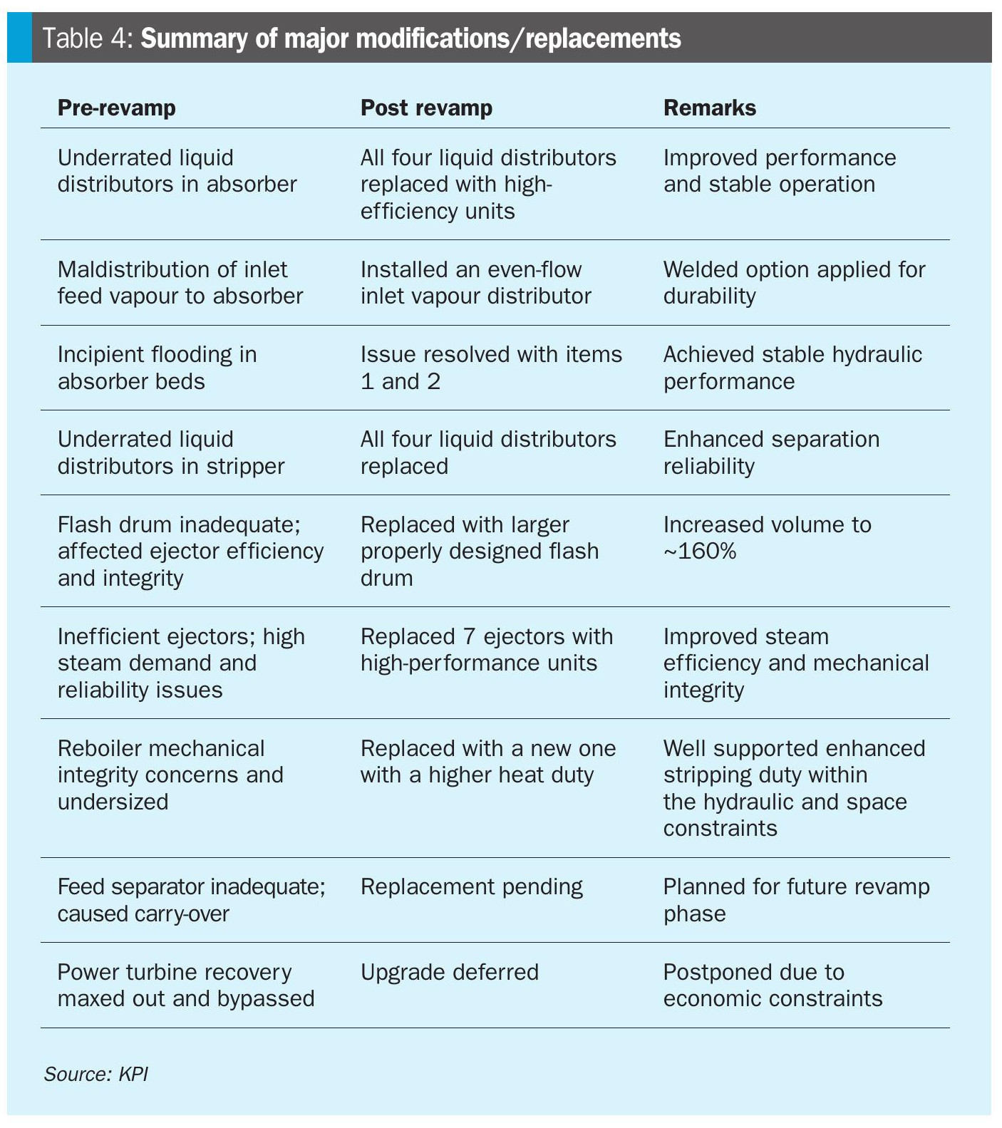
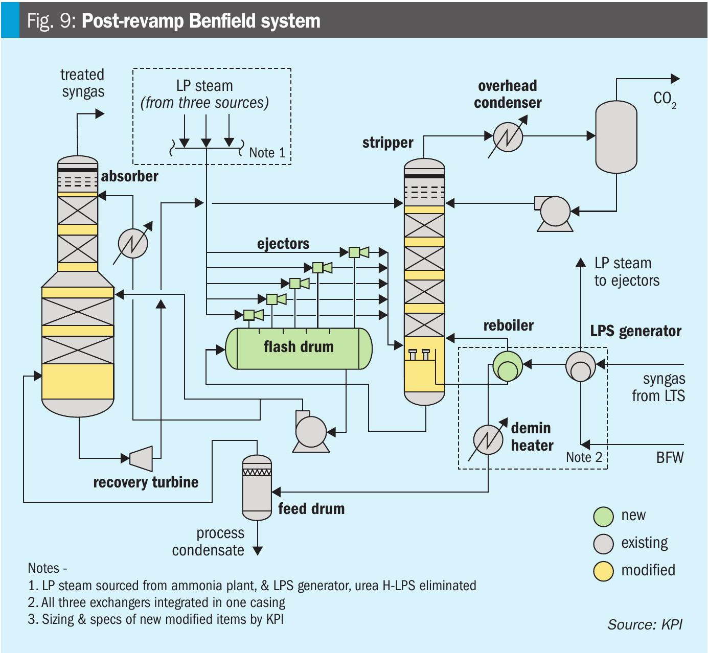
A comprehensive revamp was executed to address the hydraulic constraints, reliability risks, and energy inefficiencies identified during the Phase 1 assessment. The major upgrades introduced in the 2022 revamp are outlined in Table 4 and reflected in the post-revamp process flow diagram shown in Fig. 9.
Vapour inlet distributor in absorber
Problem: Maldistribution and high inlet velocity at the absorber feed nozzle led to poor vapour contact with the bottom bed and localised flooding.
Solution: Installed an even-flow vane-type vapour distributor to ensure uniform vapour flow and minimise localised velocity spikes.
Justification: Correcting vapour entry dynamics improved vapour-liquid contact, reduced CO2 slippage, and enhanced overall absorption efficiency.
Liquid distributors in absorber
Problem: The four absorber liquid distributors were operating well above rated capacity, resulting in overflow, uneven liquid loading, and poor bed performance.
Solution: Replaced all four absorber distributors with high-efficiency orifice-deck types, designed for higher flow capacity and improved liquid distribution.
Justification: Proper liquid distribution is critical for maintaining mass transfer surface area across the packing. This upgrade resolved localised flooding, enhanced column efficiency, and ensured stable operation.
Liquid distributors in stripper
Problem: The stripper’s four liquid distributors were severely under-rated, contributing to maldistribution and reduced column performance.
Solution: Replaced all four stripper distributors with high-efficiency designs capable of handling updated hydraulic loads.
Justification: Uniform liquid loading minimised hydraulic constraints, improved separation reliability, and enabled stable CO2 stripping performance.
Flash drum replacement
Problem: The existing flash drum was undersized, limiting vapour disengagement and contributing to ejector instability.
Solution: Installed a new flash drum (~160% larger) while maintaining the five-compartment configuration to minimise site impact and piping modifications.
Justification: Resizing the flash drum restored vapour-liquid separation reliability, improved ejector suction performance, and reduced entrainment into downstream equipment.
Ejector system optimisation
Problem: Seven aging ejectors exhibited poor efficiency, high steam demand, and mechanical integrity issues.
Solution: Replaced the existing ejectors with five modern high-performance units, optimised for available LP steam pressure and temperature.
Justification: The new configuration improved motive steam economy, eliminated the need for higher-pressure LP steam, and minimised venting in the downstream urea plant.
Reboiler upgrade
Problem: The existing stripper reboiler suffered from tube thinning and reduced heat transfer, impacting reliability.
Solution: Installed a new reboiler (designed for higher heat duty) within the existing footprint and piping constraints.
Justification: Enhanced heat duty improved CO2 stripping efficiency, reduced slippage, and stabilised thermal performance. It also reduced auxiliary boiler firing and steam consumption, lowering GHG emissions.
Feed separator (pending)
Problem: The absorber feed separator was undersized, causing excessive liquid carryover into the column.
Solution: Replacement is planned in a future revamp phase to align with current throughput.
Justification: Adequate feed separation is essential to protect column hydraulics and reduce solvent carryover.
Power recovery turbine (deferred)
Problem: The existing turbine was fully loaded and bypassed, with the largest impeller already installed.
Solution: Upgrade deferred due to economic constraints, as replacing the turbine would require major pump relocations and hardware changes.
Justification: Economic evaluation determined that the additional 225 kW power recovery did not justify the capital expenditure
Table 4 presents a consolidated summary of key modifications and replacements, linking each pre-revamp issue to the corresponding solution and its realised benefits.
Post revamp performance
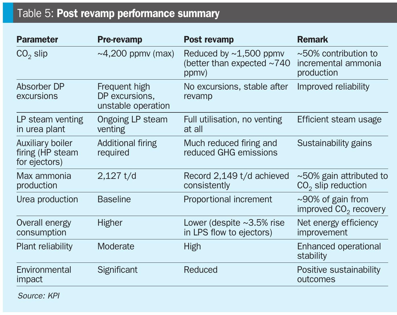
A comprehensive, simulation-driven approach was employed to revamp the Benfield CO2 removal system, enabling quantifiable performance gains and streamlined evaluation of improvement options via cost-benefit analysis. Table 5 summarises the sustained performance metrics achieved following the mid-2022 revamp.
Key improvements achieved
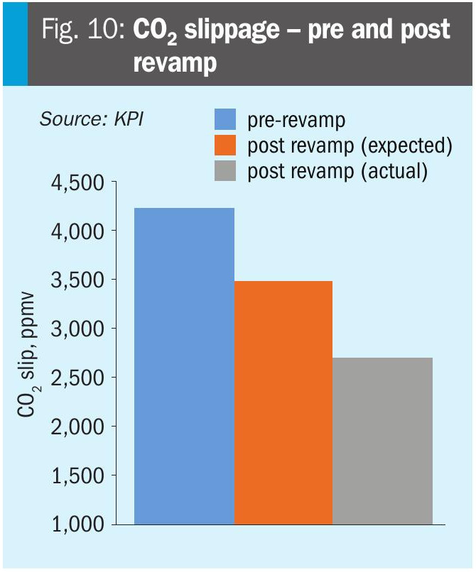
Significant reduction in CO2 slippage and capacity gain: CO2 slippage was reduced by approximately 1,500 ppmv (refer to Fig. 10), directly improving synthesis loop composition, ammonia conversion efficiency. This supported incremental gains in ammonia and urea production. The revamped system achieved record ammonia production of 2,149 t/d, operating reliably at maximum load.
Hydraulic stability and operational reliability restored: Flooding and pressure-drop excursions in both the absorber and stripper were fully mitigated through upgraded vapour and liquid distributors, resizing of the flash drum, and replacement of ejectors. Uniform vapour-liquid distribution and restored hydraulic stability now enable predictable, high-capacity operation.
Enhanced energy efficiency and environmental benefits: LP steam consumption was significantly reduced, lowering auxiliary boiler firing and improving overall energy intensity. Steam venting to the urea plant was eliminated, improving water and energy utilisation across the integrated complex. Reduced auxiliary firing led to lower GHG emissions, supporting plant-wide sustainability and decarbonisation objectives.
Mechanical integrity and enhanced reliability: Replacement of aging equipment (including the flash drum, ejectors, and reboiler) addressed structural degradation and tube thinning, significantly improving long-term operability. The system now supports extended service life, lower maintenance requirements, and reduced unplanned downtime.
Conclusion
The comprehensive revamp of the Ben-field CO2 removal system at this 2,125 t/d ammonia facility delivered transformative improvements in performance, energy efficiency, and long-term reliability. It underscores the value of a simulation-driven, systematically engineered approach to upgrading aging CO2 removal systems under increased throughput demands.
A systematic upgrade strategy was applied, combining validated process simulation with detailed hydraulic and mechanical assessments to diagnose performance bottlenecks. Improvement options were ranked using a cost-benefit framework to ensure impactful and economically viable implementation.
The revamp yielded significant benefits: restored hydraulic stability, reduced CO2 slippage, lower steam usage, and improved energy efficiency – all contributing to maximising ammonia and urea production and enhanced long-term reliability.
Although implemented in an ammonia facility, the systematic methodology and solutions are broadly applicable to aging Benfield units in refineries and petrochemical complexes facing similar operational constraints.
References