Nitrogen+Syngas 396 Jul-Aug 2025
8 July 2025
Flexible co-production of low carbon hydrogen and ammonia
DECARBONISATION
Flexible co-production of low carbon hydrogen and ammonia
By combining oxygen-blown Lurgi™ autothermal reforming (ATR) technology with Cryocap™ H2 carbon capture technology, Air Liquide offers an innovative plant configuration to meet the need for a central production facility offering flexible product diversification with hydrogen and ammonia at a scale that satisfies extensive decarbonisation targets.
Hydrogen will play an essential role in the decarbonisation of industrial applications like refineries and chemical plants, as well as mobility. Based on the specific application and the end point of use (local vs. transcontinental), several hydrogen vectors are discussed – the most popular being ammonia, liquid hydrogen and methanol. Ammonia has been in focus over the last couple of years due to its favourable properties for transport and a proven industrial supply chain. Low carbon or renewable ammonia can be used after an ammonia cracking step as a fuel or feedstock for the chemical industry. Ammonia cracking technology is currently under development and Air Liquide is preparing the start-up and operation of the first industrial pilot plant.
Liquid hydrogen is another viable option to transport low-carbon and renewable hydrogen. Although its physical properties impose certain requirements on the transport (cooling down to -253°C), it is an interesting option as the hydrogen can be readily used without the requirement of additional steps. The hydrogen liquefaction step is an industrially proven technology and the industrial readiness for long-range transport was recently demonstrated by CNOOC and Air Liquide.
Methanol is also being prominently discussed, especially for usage in the shipping industry, for example, it is currently being evaluated in the EU-funded M2ARE project with participation of Air Liquide.
However, ammonia and hydrogen have gained the most traction in recent years and both molecules have their own sweet spots with regard to type of end-use and location. Also, for some projects it is envisaged to produce ammonia for transcontinental shipping and hydrogen as a co-product for local use. In fact, the co-production of both molecules by a shared front end offer an economical benefit by economy of scale, as well as a certain degree of production flexibility – which allows for adaption of market demands.
Air Liquide has developed an innovative plant configuration to meet this need, combining oxygen-blown Lurgi™ autothermal reforming (ATR) technology coupled with Cryocap™ H2 carbon capture technology. This solution was presented at Nitrogen + Syngas conferences1,2 in 2023 and 2024 and now following the completed basic engineering and further steps towards industrial realisation, the main benefits and recent advancements of Air Liquide’s technology solution are presented.
Air Liquide technology highlights
Air Liquide’s unique technology portfolio in the field of low carbon hydrogen production covers all relevant syngas production technologies and a large number of CO2 capture technologies making it possible to evaluate different techno-combinations in order to select the most suitable and efficient combination. Air Liquide is the only licensor having its own proprietary autothermal reforming as well as carbon capture technologies and provides a one-stop for technology with full integration of the different process units.
ATR
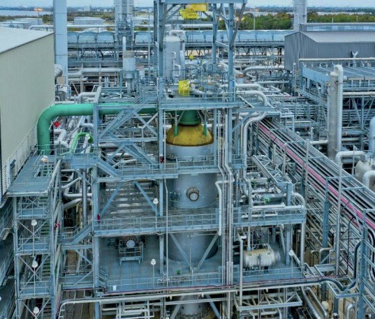
Since the acquisition of Lurgi in 2007, Air Liquide is the sole licensor of Lurgi™ ATR (Fig. 1) technology and a leading technology provider for oxygen blown autothermal reforming with in total more than 45 ATR licenses. The long cooperation with its catalyst partner Clariant ensures reliable operation at stable and high conversion rates. Air Liquide’s fully referenced Lurgi™ ATR design is in operation for up to 530 kNm3 /h of dry syngas equivalent, which corresponds to a production of approximately 6,000 t/d ammonia.
Air Liquide is also able to match the oxygen requirements of a large scale ATR.
As a world leader for industrial gases, Air Liquide can draw upon its extensive design experience and benefits from large amounts of data from industrial operational facilities. Over 4,000 air separation units (ASU plants) have been built for third party customers and Air Liquide operations.
Cryocap™ H2
Cryocap™ H2 is a technology which combines cryogenic process technologies and gas separation membranes in a unique Air Liquide proprietary CO2 capture solution. Cryocap™ H2 enables carbon capture without solvents or chemicals, effluents or waste, and with negligible steam consumption. In the first step, the shifted syngas from the ATR and downstream CO shift units is fed to a hydrogen pressure swing adsorption (PSA) unit, where it is split into a pure hydrogen product and a low pressure, CO2-rich tail gas product. The tail gas from the PSA unit is then compressed and fed to the cryogenic section, where the CO2 is separated from the other components of the PSA tail gas stream by a combination of partial condensation and distillation. The core of the process is based on the partial condensation, as the high purity CO2 product is first obtained as a liquid and is ultimately evaporated in the main heat exchanger of the cryogenic section at different pressure levels, thereby providing the refrigeration requirements of the separation process.
The non-condensable stream, from the cryogenic section is routed to a series of membrane modules for further separation. The membrane unit comprises two stages of Air Liquide’s proprietary MEDAL™ PIX H2 membranes. Here, the non-condensable stream is separated into two product streams:
- a stream enriched in H2 that is recycled to the PSA inlet;
- a high pressure off gas stream, containing most of the non-condensable (CO, N2, H2, CH4, and some CO2), which is recycled to the reforming section.
A direct CO2 capture rate for this setup can be as high as >99% and brings additional value for reducing scope 3 emissions, which is discussed in detail in the next section.
The application of Cryocap™ H2 for low carbon ammonia production in an ATR also offers integration options for liquid CO2 production at marginal additional energy requirements, due to its cold operating conditions1.
Cryocap™ H2 has been in commercial operation by Air Liquide in Port Jerome, France since 2015 and is the only cryogenic CO2 separation technology that has been demonstrated for low carbon hydrogen in an industrial operation.
Air Liquide’s integrated in-house PSA technology is referenced in more than 80 own and third party plants.
The experience in membrane design by Air Liquide is based on more than 175 hydrogen systems globally and over 2,900 membrane modules in service.
Low carbon hydrogen and ammonia co-production
The co-production of ammonia and methanol has been known for 20 years and has been done in several locations worldwide. However, the co-production of ammonia with significant amounts of low carbon hydrogen is new in the industry. The conventional ammonia production process via air blown secondary reforming does not offer a straightforward way to branch-off hydrogen as a co-product as nitrogen would have to be removed from the syngas.
Several projects in the past years have envisaged the common production of low carbon ammonia and hydrogen, most of them in the USA and Canada.
As one example, Air Liquide and other stakeholders have agreed to collaborate in the development of a production plant for more than 1.1 million tonnes per year of low carbon ammonia in Houston, TX, USA. The plant will be able to flexibly export a part of the low carbon hydrogen as chemical purity product. Air Liquide will provide the technology and design for the ammonia syngas generation, including the ATR, ASU and Cryocap™ H2.
Fig. 2 shows a block flow diagram of a production scheme for low carbon ammonia and hydrogen, applying an ATR and Cryocap™ H2. An ASU provides the oxygen for use in the ATR and the required nitrogen for the ammonia synthesis. Natural gas is desulphurised and then reformed with oxygen from an ASU at temperatures around 1,000°C. The hot reformed gas (syngas) is cooled by raising steam. The remaining CO in the syngas is converted to CO2 and hydrogen in a CO shift section.
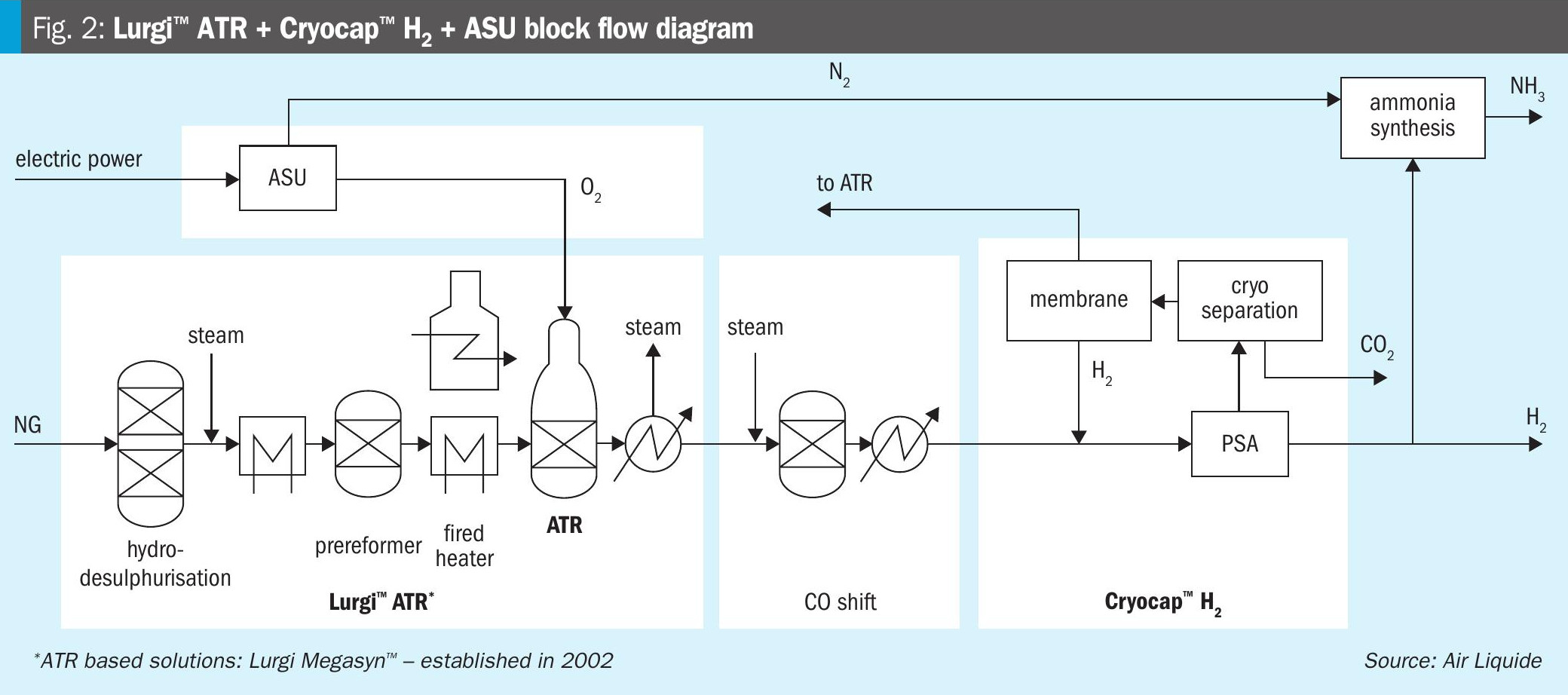
The PSA unit produces a high purity hydrogen from the syngas. The PSA tail gas is treated in the Cryocap™ H2 unit, where high purity CO2 is separated in a cryogenic process combining partial condensation and distillation. The remaining gas is separated using membrane technology, preparing an H2-rich stream and a CO and CH4-rich stream.
The H2-rich stream is recycled to the PSA unit to increase the H2 product or used for hydrogen fuelling in the fired heater. The CO and CH4-rich stream can be recycled to the ATR or used as fuel in a fired heater.
The water-free CO2 product is of high purity (>99.9 mol-%) and can be used without further treatment for sequestration, utilisation and even liquefaction.
The CO2 product is sent to the battery limit for storage or utilisation. The purified hydrogen is split into two portions: the hydrogen product and the portion which is used for ammonia synthesis. The latter is mixed with nitrogen from the ASU to form the syngas for ammonia production and is then fed into the ammonia loop.
This Air Liquide proprietary setup offers a distinctive advantage in carbon emission reduction. In general, the carbon intensity of the hydrogen generation process is classified into three principal categories i.e. scope 1, scope 2 and scope 3 carbon intensity. Scope 1 carbon intensity is governed by the direct emissions of the plant which a process minimises by maximising the direct carbon capture rate. Scope 2 carbon intensity can be minimised by ensuring renewable electricity import (down to 0 kg CO2/kg H2). Hence, scope 3 emissions become a significant driver of the overall carbon intensity.
Scope 3 emissions can be classified in the following two main components:
- carbon atomsgoingwithH2 product as impurity (low-impact parameter);
- carbon intensity of the natural gas fed to the hydrogen plant (high-impact parameter).
In order to produce a H2 product ready to be exported for downstream use e.g. chemicals industry, refinery, liquefaction or pipeline, the purity requirement is high enough to minimise the scope 3 emission associated with the H2 product to a minimum (essentially zero or close to zero). Moreover, it is much easier to optimise the product purity level to meet the carbon intensity target.
Hence, effectively, almost the whole contribution of the scope 3 carbon intensity is tied to the hydrocarbon feedstock (typically, natural gas) upstream of the plant. This is also a relatively hard-to-abate section and typically the order of magnitude of specific carbon intensity is much higher (e.g. 7-9 kg CO2e/million Btu LHV of natural gas). Therefore, minimisation of natural gas intake is definitely a crucial driver for all the decarbonisation.
The scope 3 emission reduction is achieved by two specific characteristics of the ATR+Cryocap™ H2 solution. Firstly, the effective H2 recovery of the process is significantly boosted by the combination of PSA and Cryocap™ H2 to >99% compared to ~89% for a standalone PSA, while accomplishing a CO2 recovery from syngas of >99%. This in turn reduces the natural gas consumption of the process. Secondly, the use of membrane technology enables the recycling of carbon containing syngas components (CO, CH4) to the ATR section and enhances the process efficiency by carbon recovery.
Also, as no steam is required for Cryocap™ H2 compared to a state-of-the-art amine wash, less natural gas is required for the steam raising, which can be used in process integration, enabling a higher process efficiency – for example in the setup covering ATR, gas heated reforming and Cryocap™ H2, which was patented by Air Liquide.
Besides, as an ASU supplies oxygen to the hydrogen plant, from an operating cost as well as scope 2 emission points of view, minimisation of oxygen intake should be of interest as well as it is a direct function of natural gas intake to the plant.
Referring to the points addressed above, Air Liquide’s ATR + Cryocap™ H2 + ASU is a solution providing H2 and NH3 production with the lowest achievable carbon intensity and cost of production.
Case study
Several case studies for oxygen-blown ATR based production for low carbon hydrogen have been conducted by Air Liquide, covering the envisaged usage of H2 molecules for:
- chemical industries (>99.9 mol-% H2), e.g. hydrogenation in refineries, for liquefaction and transport;
- fuelling purpose (>95 mol-% H2), e.g. power plant decarbonisation or cracker decarbonisation;
- ammonia production;
- ammonia-hydrogen co-production.
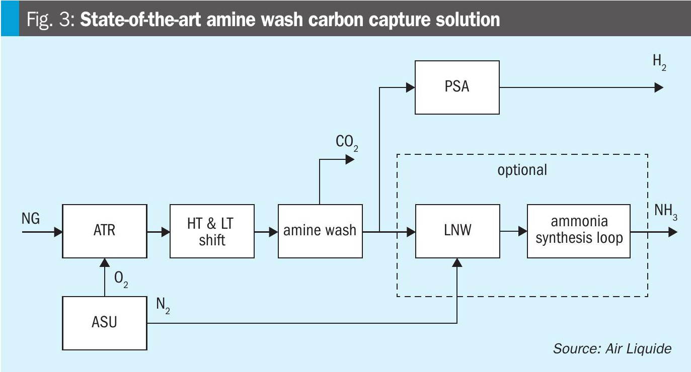
In general, two types of flowsheets have been compared: a state-of-the-art amine wash carbon capture on the syngas, and Air Liquide’s proprietary solution applying Cryocap™ H2. Fig. 3 depicts the state-of-the-art solution: Syngas is produced by an oxygen-blown ATR, the syngas is shifted in two CO shift units. The CO2 from the syngas is then captured by an amine wash unit, dried and pressurised to supercritical state before being exported. The decarbonised syngas is then further processed as required depending on the envisaged product(s). For ammonia production a liquid nitrogen wash (LNW) unit is applied for syngas preparation, a PSA is applied for hydrogen production and for co-production both units are used in parallel.
The second flowsheet is based on Air Liquide’s innovative solution and is depicted in Fig. 4. The raw syngas derived from the oxygen-blown ATR is also shifted in the CO shift units and then routed to a PSA unit where high purity hydrogen is produced and the PSA tail gas is treated in the Cryocap™ H2 unit. A CO2 product is prepared in the cryogenic part before being pressurised to supercritical state and valuable gases such as H2, CO and CH4 are recycled to the ATR frontend or the PSA.
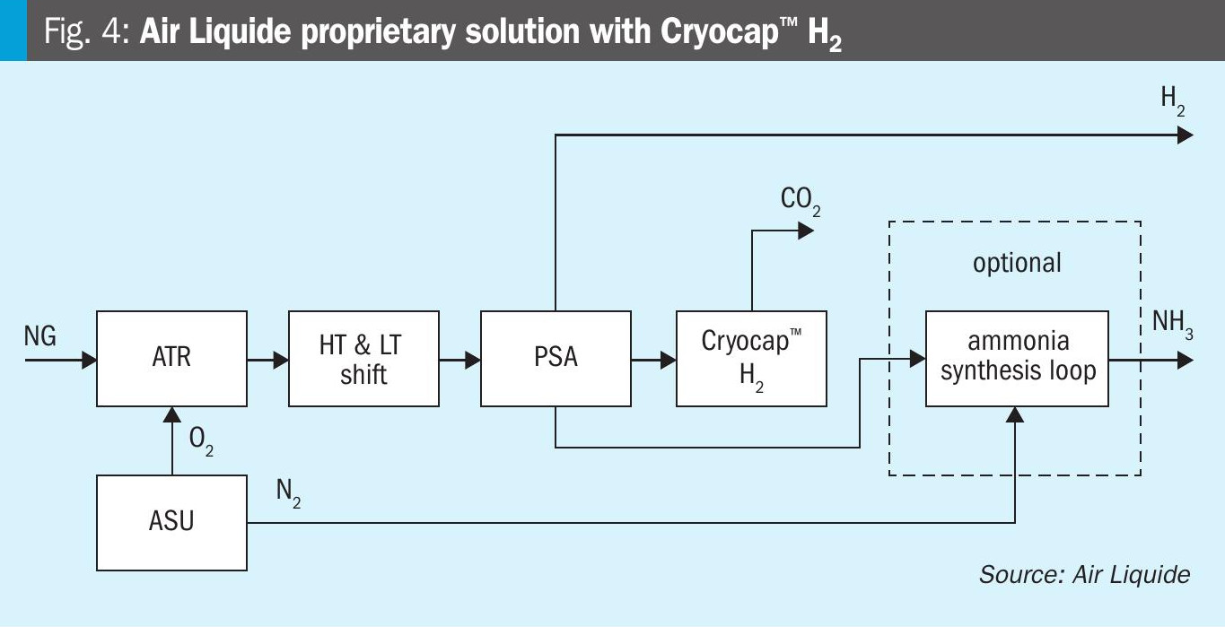
The further treatment of the hydrogen from the PSA is independent from the envisaged product(s). For hydrogen production, obviously no further treatment is required. For ammonia production, only nitrogen has to be mixed with the syngas. For co-production of ammonia and hydrogen, no additional treatment step is required. This leads to several advantages, which will be further demonstrated in the case studies below.
Low carbon hydrogen production (chemical grade)
The scenario for the production of chemical grade H2 (>99.9 mol-%) as the only product is compared in Table 1.
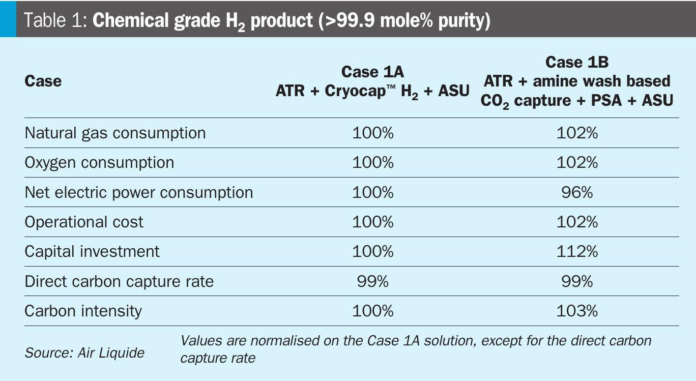
The natural gas and oxygen consumption of the Air Liquide proprietary solution (Case 1A) is reduced compared to the state-of-the-art solution (Case 1B), as the hydrogen recovery is higher due to the membrane based separation step for the PSA tail gas, where H2 is recovered and routed back to the PSA. Hence less natural gas feedstock and oxygen are required. However, the electrical consumption is increased, as compression of the PSA off gas has to be considered for the Cryocap™ H2 unit in order to meet the carbon capture rate. However, an intrinsic advantage of the Cryocap™ H2 is that the CO2 is obtained at elevated pressure or already liquefied without any increase on electrical duty compared to the amine wash, which delivers the CO2 at atmospheric pressure and is saturated with water requiring an additional dehydration unit and results in a higher electricity consumption to achieve pressurised supercritical CO2.
Overall, a significant saving on the operational cost and capital investment can be realised with Air Liquide’s solution. The capital investment difference mainly attributes to lower gas/material flow through the process chain reducing the equipment sizes and the high modularisation potential for the Cryocap™ H2 solution.
While the direct carbon capture rate is the same, the carbon intensity is higher for Case 1B, which is directly linked with the natural gas consumption.
Low carbon hydrogen production (fuel grade)
Fuel grade hydrogen production is applied for example for the decarbonisation of power plants or steam crackers. For this production scheme, a specific point has to be considered in process design: there is no requirement of high purity H2 as it will be used for combustion only. Hence no dedicated hydrogen purification unit (e.g. PSA) is required from a technical view point. However, the lack of this hydrogen purification leads to a considerable slip of carbon molecules with the product H2, which will ultimately increase the scope 3 emission from the plant. For fuel grade hydrogen production in this article, the loss of molecular carbon with the product is considered as a direct emission, as the H2 product is assumed to be combusted leading to emissions to the atmosphere.
In Table 2, the parameters for the two flowsheets are compared for fuel grade hydrogen production. For the Air Liquide proprietary solution (Case 2A), a PSA is still included as it is an intrinsic part of the Cryocap™ H2 and prepares the feed gas. Also the state-of-the-art solution with an amine wash (Case 2B), includes a PSA unit to minimise the carbon losses with the hydrogen product. For the recycle of the PSA tail gas, a compressor is foreseen, to route most of the gas back to the reforming section. As the PSA tail gas is available at close to atmospheric pressure and the reforming section operates typically in the range of 30-50 barg, a significant electricity consumption is added on the state-of-the-art solution. This dilutes the intrinsic electricity consumption difference to the ATR + Cryocap™ H2 solution.
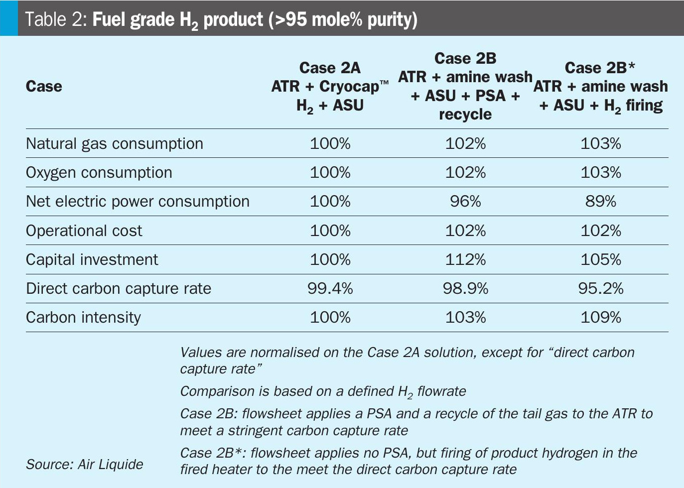
Although PSA tail gas is recycled and minimum carbon loss is attained, no separation of the carbon molecules and the H2 is done in the PSA tail gas as there is no membrane foreseen as it is in a Cryocap™ H2. So the H2 molecules in the tail gas are run through the ATR reactor a second time, consuming energy. On the other hand, the H2 molecules in the PSA tail gas in Case 2A, are returned to the PSA and end up in the product. Hence, for the natural gas and oxygen consumption, a clear advantage is apparent for ATR + Cryocap™ H2 solution and so is reflected in the cost of operation.
For Case 2B*, a H2 purification unit has not been considered for the ATR + amine wash based solution, leading to lower power consumption than Case 2A. However, as discussed above, this leads to higher emissions of carbon via the H2 product and a lower carbon capture rate. To meet a state-of-the-art threshold direct carbon capture rate of 95%, part of the product H2 firing is foreseen, which leads to a higher natural gas and oxygen consumption.
Another option for producing a low carbon fuel grade H2 is to use a methanation instead of PSA. By doing so, the heating / fuel value of the H2 product is increased as in the methanation reaction the impurities CO and CO2 are converted with hydrogen to methane. However, this in turn leads to loss of hydrogen, as it is a reactant of the methanation reaction, which leads to a higher natural gas and oxygen consumption. This ultimately increases scope 2 and scope 3 emissions.
In case the product is specified by the heating value (MWh or GJ/h) and not by the product flowrate (t/h or Nm3/h), then the difference between the cases in Table 2 becomes smaller as there is no additional penalty on H2 yield anymore. However, to meet a state-of-the-art direct capture rate threshold, operational cost advantage favours the ATR + Cryocap™ H2 solution.
Low carbon ammonia production
If low carbon ammonia is envisaged, an ammonia synthesis loop as an additional techno-block will be added to the flowsheets. Thanks to the collaboration with KBR, Air Liquide is able to offer a one stop shop solution for fully integrated oxygen-blown ATR-based low carbon ammonia solutions utilising KBR’s leadership in ammonia production technology. Together, a unique one-stop solution for the industry is provided, delivering exceptional energy efficiency, reliability, and carbon capture rates of up to 99% in integrated facilities. For the ATR + Cryocap™ H2 solution (Case 3A), the advantage is that an inert-free syngas is already prepared by the PSA and high purity N2 is available from the ASU.
For Case 3B, featuring the amine wash based CO2 capture, typically a LNW unit is foreseen to absorb any oxygenates along with unconverted methane. The liquid nitrogen is supplied by the ASU and in this step, gaseous nitrogen from ASU is also mixed with the H2-rich gas so that at the exit of the LNW unit a syngas is obtained that is suitable for the ammonia synthesis loop. In Table 3, a comparison of the critical parameters for the two different flowsheets is made.
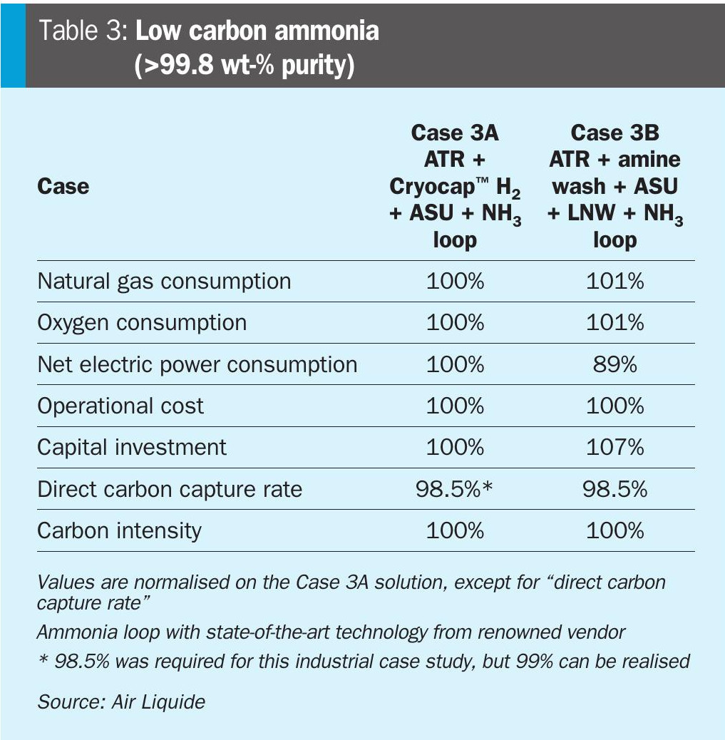
It can be observed that the difference in the operational cost between the two cases is negligible. The principal reason for that is the ammonia production process is mainly power-driven due to the huge compression duties for the syngas and ammonia refrigeration compressors. Hence, the net electric power consumption does not bring any benefit to the ATR + Cryocap™ H2 solution (Case 3A). Having effectively the same operational cost, ATR + Cryocap™ H2 results in lower capital investment cost which leads to net lower levelised cost of ammonia, while achieving the same direct carbon capture rate and total carbon intensity.
Moreover, it is clear from the table that the main contributor of the carbon intensity for Case 3A is the electrical power consumption (scope 2 emissions). The natural gas consumption (scope 3 emissions) is lower for this solution. Hence, if decarbonisation of the power grid is realised, the potential is clearly more for the ATR + Cryocap™ H2 solution to accomplish the lowest carbon intensity.
Co-production of hydrogen and ammonia
Referring to the above discussions, it is clear that for the production of both chemical grade H2 and NH3, ATR + Cryocap™ H2 solution brings certain advantages. This means for co-production of these two decarbonised molecules, this solution will be even more advantageous. In Table 4, a comparison for critical parameters for the two different cases are illustrated.
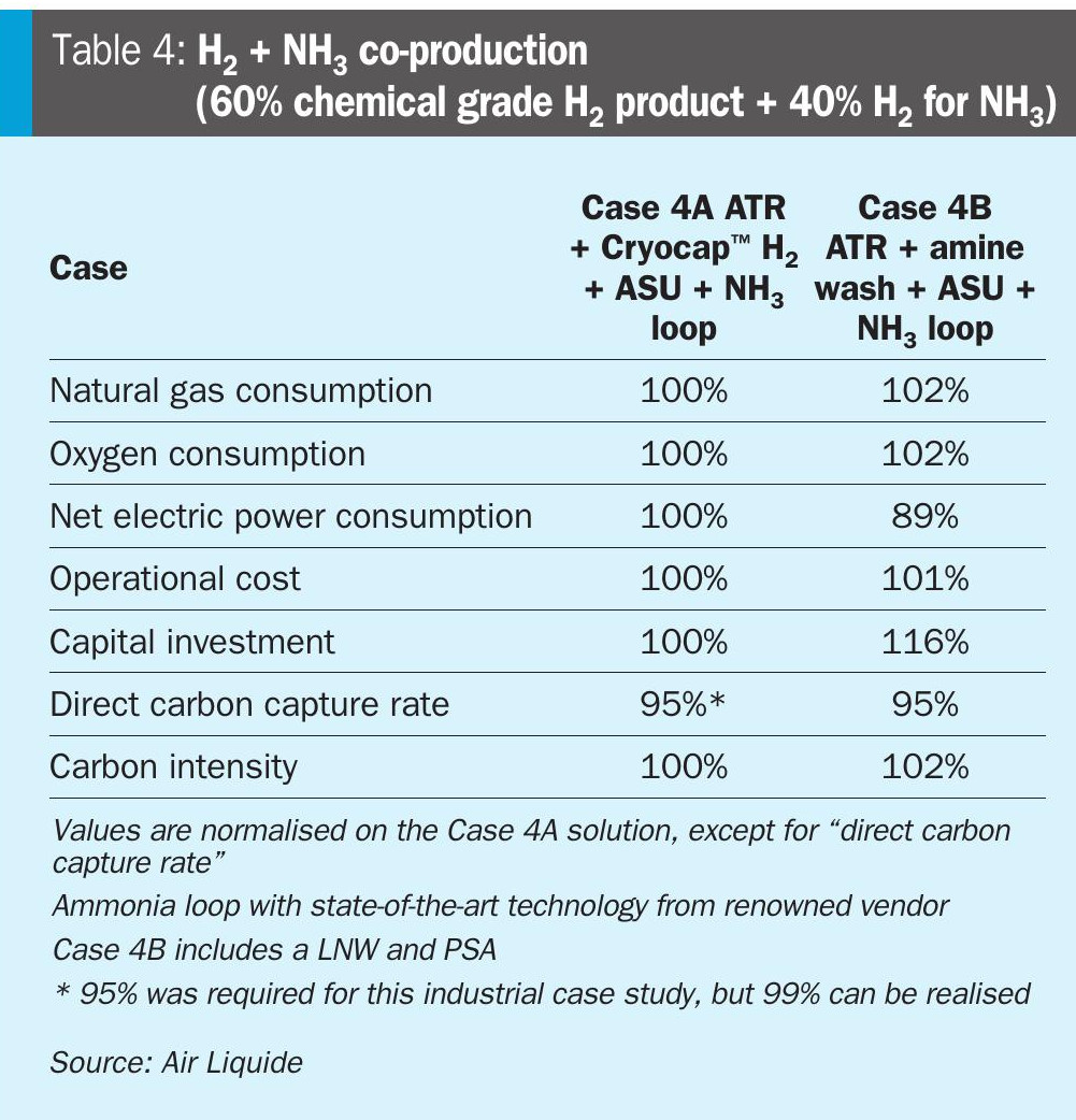
For co-production, there is a need to produce a pure H2 product at one of the process steps. If ammonia production is the objective, in a typical ATR + amine wash based CO2 capture solution with LNW, there is no pure H2 production step. Hence, to obtain a co-production scheme, an additional H2 purification unit (PSA) will be required for the amine wash based solution. This adds capital expenditure to the solution (Case 4B). In contrast, the ATR + Cryocap™ H2 solution already has an intrinsic PSA step. In other case studies, the application of a PSA instead of a PSA + LNW was evaluated for the state-of-the-art solution. It was observed that the additional compression duty of the PSA tail gas to meet the H2 and CH4 recovery from the syngas imposed a large penalty on the setup, making it less competitive compared to a PSA + LNW based setup. This can also be seen in the Case 1B results for chemical grade hydrogen, as this setup serves the same purpose, but without the additional markups for an ammonia loop.
Table 4 shows that, for a co-production scheme where 40% H2 is being used to produce ammonia, ATR + Cryocap™ H2 solution brings up the expected advantages from the other scenarios, the power consumption difference between the solutions also gets reduced, while the difference between capital investment cost between the two solutions gets increased favouring the ATR + Cryocap™ H2 solution even more attributing to the additional H2 purification unit and thus additional tail gas compression and recycling in Case 4B.
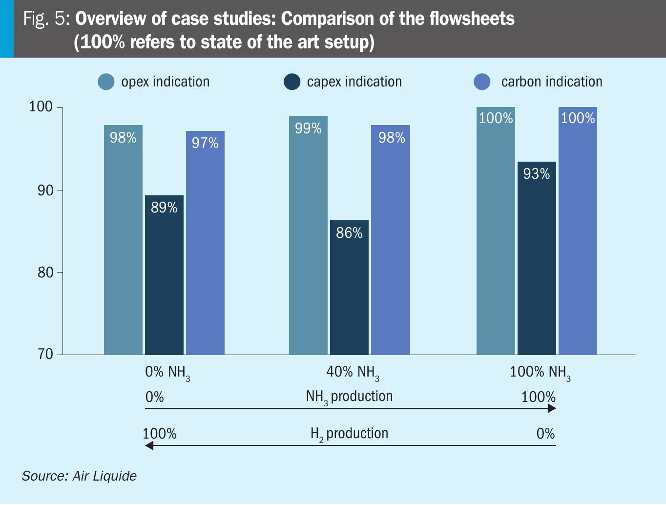
Fig. 5 displays the results of the case studies and the overall performance of the Air Liquide proprietary solution versus the state-of-the-art amine wash based setup. It can be observed that if low carbon hydrogen is envisaged as the sole product, the Lurgi™ ATR plus Cryocap™ H2 solution shows decreased opex and also significantly decreased scope 3 carbon emissions. The capex parameter is remarkably decreased by 11% compared to the state-of-the-art solution, due to the increased H2 recovery and smaller throughput through the unit as well as the modularised layout. If ammonia and hydrogen are produced, the opex of the Air Liquide solution and the state-of-the-art solution are at the same level, but the capex is drastically decreased as only one common hydrogen purification unit (PSA) is used compared to the state-of-the-art case (PSA + LNW). For the co-production case, the scope 3 emissions are also decreased compared to the state-of-the-art due to the use of Air Liquide’s MEDAL™ PIX membranes for carbon recycling and hydrogen recovery. If only low carbon ammonia production is envisaged, the setup based on Cryocap™ H2 shows a lower capex at comparable operational expenditure and scope 3 emissions.
Conclusion
Air Liquide is committed to enable sustainable low carbon hydrogen production and offers an innovative production scheme based on the renowned Air Liquide technologies Lurgi™ ATR, Cryocap™ H2 and ASU.
These three key technologies have a successful industrial track record and can be flexibly integrated by Air Liquide for low carbon hydrogen. In addition, customers benefit from Air Liquide’s expertise in EPC and as an owner/operator, drawing on 60 years of experience across the entire hydrogen value chain.
The overall concept is currently underway to industrial realisation in the USA and Air Liquide is ready to supply it to its customers to support their decarbonisation targets worldwide.
References