Sulphur 418 May-Jun 2025

1 May 2025
Detecting and preventing SO2 breakthrough
CLAUS TAIL GAS TREATMENT
Detecting and preventing SO2 breakthrough
Debopam Chaudhuri, Ayan Dasgupta and Marcus Weber of Fluor discuss the main causes, detection techniques, management methods and prevention procedures of SO2 breakthrough in the quench water system of a TGTU, with some unique design features for Fluor’s Desuperheater Contact Condenser.
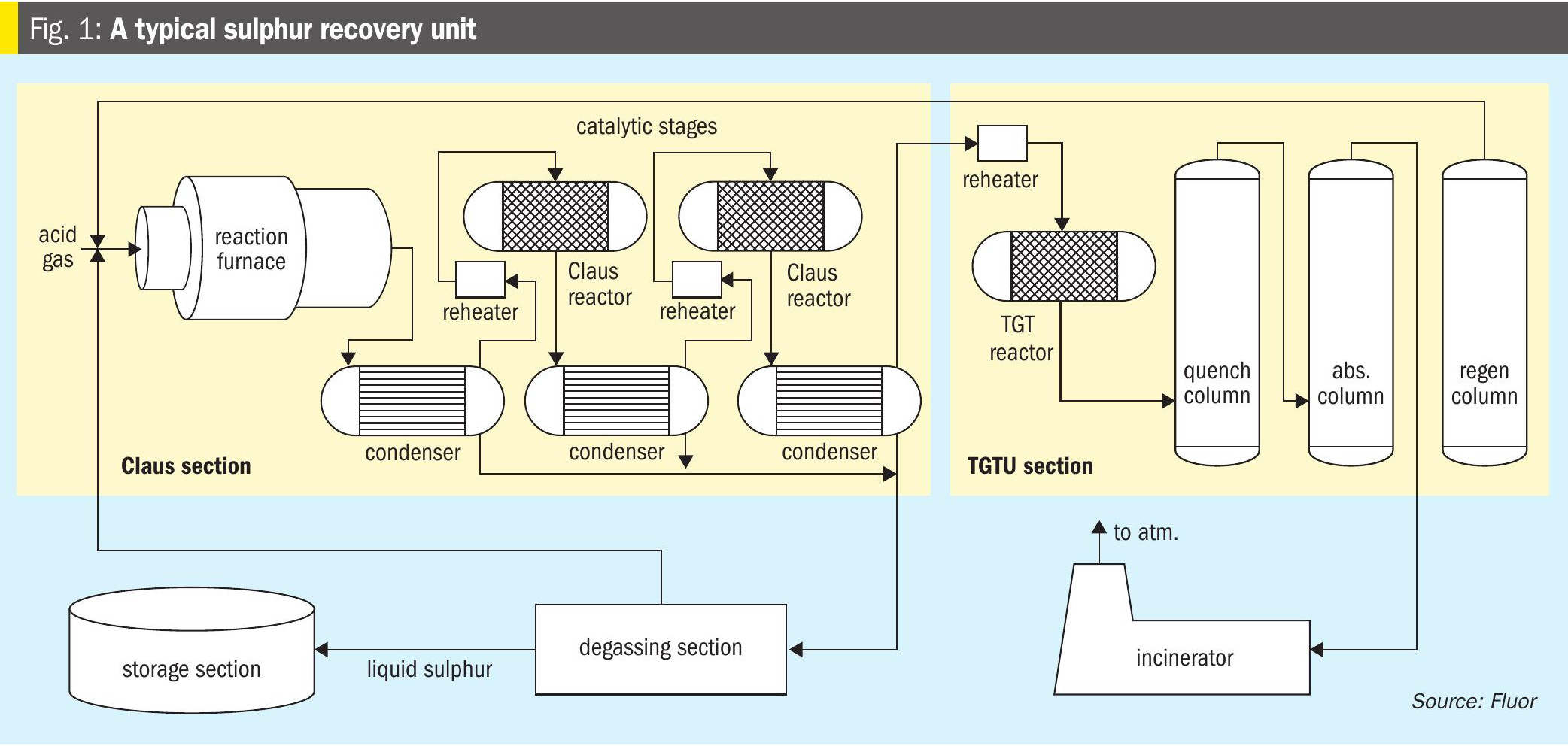
In a typical sulphur recovery unit (SRU) most of the sulphur recovery takes place in the thermal and catalytic stages. But since the reaction is limited by equilibrium, complete conversion cannot be achieved. A sulphur recovery unit with two catalytic reactors can typically recovery around 95% of the sulphur. Most modern plants target a sulphur recovery of well in excess of 99%, hence a tail gas treatment unit is provided. Purification of sulphur produced in the thermal and catalytic stages is achieved via degassing, while unconverted sulphur compounds are typically incinerated in a thermal oxidiser (see Fig. 1).
A reduction-absorption-regeneration tail gas treatment (TGT) unit is recommended to achieve high sulphur recovery numbers. In the TGT section, all the sulphur components are first converted into H2S in the TGT reactor or the hydrogenation reactor using a catalyst. The reactor effluent is then cooled in a quench column which also removes a large amount of water vapour, the H2S in the acid gas is then absorbed in an amine solution and regenerated and recycled back to the reaction furnace. In this way, this amount of sulphur is never lost from the process, allowing an almost complete sulphur recovery from the overall unit. Typically, a recovery of 99.9% is achieved by this configuration.
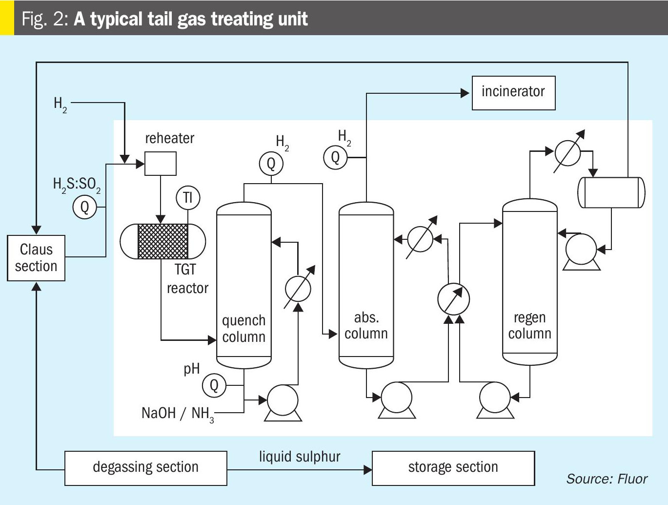
The tail gas from the Claus section contains small amounts of unconverted H2S, SO2, small amounts of COS and CS2, and traces of sulphur as mist or vapour. The amount of these species is dependent on the sulphur recovery efficiency of the Claus section. The reduction-absorption-regeneration process is based on the concept of reducing the SO2 to H2S, CS2 and COS to CO2 and H2S and the sulphur is reduced to H2S in the hydrogenation reactor; then absorbing all the H2S in an amine solution, and finally regenerating the H2S from the amine solvent to recycle the gas back to the Claus thermal stage (Fig. 2).
The reactions are as follows:
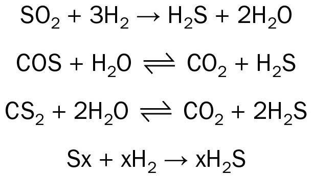
The tail gas from the Claus thermal and catalytic section is first heated up in the reheater, and then reduced in the TGT or the Hydrogenation reactor over a bed of CoMo catalyst. The required reduction atmosphere is maintained in the reactor such that all sulphur species in the tail gas are reduced to H2S. The process gas is then cooled. A heat exchanger to generate LP steam is implemented in some designs as the first cooling element in the scheme. It is then cooled in the quench column with direct contact with water. The additional amounts of water in the process gas are also removed in this column. The H2S in the cooled process gas is then absorbed using a suitable amine solution in the absorber column, and process gas containing trace amounts of H2S is incinerated in the thermal oxidiser. The rich amine is regenerated in the regenerator column to liberate the H2S stream and that is then recycled back to the reaction furnace.
SO2 breakthrough in quench column
The TGT design includes a quench column downstream of the hydrogenator reactor, mainly to cool the reactor effluent gases before it encounters the amine solvent in the absorber column. Quenching of the process gas is achieved by direct contact of water in a packed bed column. The quench tower, while cooling down the process gas, also condenses an appreciable amount of water thus helping in maintaining the solvent strength in the amine circuit. The quench column also serves as a guard against possible SO2 slippage from the upstream hydrogenation reactor into the amine solution. The circulating water in the quench column circuit is maintained at a slightly basic condition with a target pH of 8 to 9. SO2 breakthrough into the quench column is manifested by turning the quench water cloudy due to precipitation of sulphur and is indicated by a sudden and/or a remarkable reduction of the pH value. Hence there is always an analyser measuring pH in the quench water circuit. An immediate caustic or ammonia injection into the quench water is recommended to maintain its basicity. But one needs to look for the real reasons for SO2 breakthrough.
How bad could SO2 breakthrough be?
The “milky” quench water has the potential to result in major plant upsets and can be the cause of permanent damage and losses in the SRU.
In case the tail gas analyser is not working properly, thus losing control over the Claus furnace combustion, the tail gas composition can become very abnormal, meaning the H2S:SO2 ratio would be extremely skewed. With very high amounts of SO2 entering the TGT reactor, the reactor exotherm may even lead to catalyst damage, and a potential for SO2 slippage in the downstream quench water circuit.
The SO2 slippage in the quench column can wreak havoc in the quench water system. The quench water turns acidic in nature, with pH values reaching as low as 3 under extreme conditions of SO2 slippage. The acidic quench water can lead to excessive corrosion in the quench water systems, which might not be visible right away, but leads to choking of filters and strainers in the quench water system and damages equipment and piping in the long term.
The SO2 neutralises the small amounts of ammonia or caustic in the quench water immediately and starts to slip downstream into the amine system. SO2 can form heat stable salts thus reducing the selectivity and absorption capacity of the amine. The H2S is not completely absorbed by the amine, and passes through with the process gas to the incinerator, which ultimately leads to higher emissions of SOx from the incinerator. This also leads to loss of sulphur and hence not meeting the required sulphur recovery efficiency for a unit.
H2S and SO2 in “milky” quench water medium also has a very high potential of forming elemental sulphur via the Claus reactions. The sulphur formed can lead to deposition, choking of filters and blockages in the piping elements in the quench water system.
The symptoms and looking for the cause
Typically, the SO2 breakthrough is associated with a reduction in the pH readings as measured by the pH analyser in the quench water circuit. The immediate recommendation for this is the dosing of the neutralising agent (ammonia or caustic); this helps in bringing the pH readings back in the normal range but does not address the real reasons behind this reduction in pH. Thus, the ammonia or the caustic dosing addresses the “symptom” without providing the real “cure” for the condition.
The reasons behind SO2 slippage into the quench column can be attributed to multiple reasons, and the actual reason could easily be understood by a verification of certain other parameters. The most important ones are: tail gas analyser reading;
• tail gas analyser reading
• TGT reactor exotherm;
• hydrogen analyser reading.
Tail gas analyser reading
The reaction furnace operates on a sub stoichiometric air requirement supply such that only 1/3 of the total amount of H2S is combusted to form SO2. The air supply guide to the reaction furnace is controlled in two steps; the major control for the main air flow is dependent on the amount of acid gas sent to the furnace while a fine control for the trim air flow is done by checking the tail gas composition. The tail gas composition is measured by an analyser, also known as the air demand analyser, which measures the amount of H2S and SO2. The ideal ratio between these two components is 2, and based on any deviation from this target ratio the trim air flow to the reaction furnace is controlled.
Firing the Claus furnace without proper air stoichiometry may result in higher amounts of SO2 in the tail gas. This could easily be detected by the tail gas analyser reading, and if the deviations are minor it should automatically be controlled by the trim air flow controller. But any major and a sudden change in the feed gas composition or failure in the air controller can lead to abnormal firing in the reaction furnace thus leading to abnormal ratio between H2S and SO2 in the tail gas.
Improper firing in the reaction furnace when detected by the tail gas analyser, measuring higher amounts of SO2 would also show via a higher TGT reactor exotherm due to the fact that more SO2 is being reduced in the reactor. This would also be accompanied by either a higher-than-normal hydrogen import or show a slight dip in the hydrogen concentration downstream of the quench column, depending on the normal hydrogen balance for the unit. Typically, the tail gas contains enough reducing power such that there is no hydrogen import required. With this being the normal condition, the expectation is that, when there is a major SO2 breakthrough, the normal hydrogen concentration would start to reduce, and then based on the set point of the H2 analyser would start an automatic hydrogen import to maintain the required reducing atmosphere in the hydrogenation reactor.
TGT reactor exotherm
SO2 slippage into the quench column can also be attributed to reduced catalyst activity in the hydrogenation reactor. This condition is typically easier to detect, as this would be evident from a low reactor exotherm even though the hydrogen concentrations are healthy, or even the tail gas compositions are normal.
Reduced catalytic activity in the TGT reactor means improper or incomplete conversion of SO2 to H2S. The unconverted SO2 would pass to the quench water system, which would ultimately be detected by a low pH. In this condition, the hydrogen import value would be lower than normal, or the hydrogen concentration would be slightly higher at the quench column outlet. Since loss of catalytic activity is typically a time consuming and gradual process, the loss of reactor exotherm would be a slow process and typically would extend over a long period. Hence proper monitoring of the reactor exotherm is always recommended to check the TGT reactor and catalyst health.
A higher than normal reactor exotherm also can be the cause of SO2 breakthrough. This is typically initiated by a higher amount of SO2 in the tail gas leading to more reactions and hence a higher exotherm in the TGT reactor.
Hydrogen analyser reading
The hydrogen concentration as recorded by the hydrogen analyser is always an indirect monitoring of a potential SO2 breakthrough condition.
A higher than normal hydrogen concentration reading can mean incomplete reactions in the TGT reactor. Thus, if a high hydrogen concentration reading is accompanied by a low reactor exotherm, that then becomes a clear indication of SO2 slippages from the TGT reactor.
A lower than normal hydrogen reading is an indication of an inadequate reducing atmosphere in the TGT reactor based on the process gas compositions. This condition should typically be accompanied with higher than normal reaction exothermicity or even higher SO2 readings in the tail gas.
Thus, there are multiple reasons for an SO2 breakthrough from the TGT reactor, and the actual reason can be easily investigated and concluded by looking at various other parameters in the unit. Hence while we monitor lowering of pH values in the quench water system it is always recommended to look at other parameters around the unit to assess the actual reason of SO2 breakthrough.
A case study
In this case study, a sulphur plant lost air flow control due to the malfunction of the air demand analyser or the H2S:SO2 tail gas analyser. The air flow to the reaction furnace was much more than the required amount for a considerable period of time leading to much higher amounts of SO2 in the tail gas flow into the TGT. The outcomes of such a catastrophic SO2 breakthrough are immense as defined here:
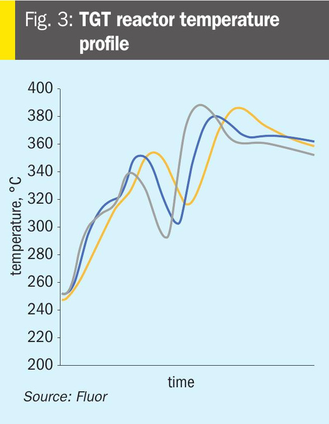
- The reactor exotherm was very high, and the reactor temperature measured by the temperature elements measuring the catalyst bed temperature reached elevated temperatures nearing 400°C. Exposure to such high temperatures led to permanent damage in the catalyst as was evident when the plant was restarted after taking a shutdown. The unit was not able to operate at capacity greater than 70% of its nameplate capacity due to reduced catalyst activity, and partial replacement of the catalyst was required.
- The quench water circuit reported symptoms of a massive SO2 breakthrough. Multiple change overs were required for the quench water pump due to choking of the suction filters. A detailed inspection was recommended for the quench water circuit to determine the extent of corrosion issues in the system.
- The amine solvent also reported reduced activity as was evident by higher amounts of H2S slippage in the absorber column, leading to high SO2 emission numbers in the incinerator, higher than the normal or permissible values.
The graph in Fig. 3 shows the temperature excursion in the TGT reactor for the above-mentioned case study. The three separate lines are for the temperature measured at various depths of the catalyst bed in the TGT reactor over the period where the unit continued to operate with higher than required amounts of combustion air in the Claus furnace.
Prevention is better than cure
SO2 breakthrough can be a painful experience for any TGT hence it is always preferred to prevent it from happening. Especially because a low pH alarm already indicates a considerable amount of SO2 in the quench water, and its subsequent consequences. Proper monitoring is extremely important, to note the important parameters of the process which could indicate the potential for an imminent SO2 breakthrough. All analysers in the SRU have a specific purpose and hence proper monitoring and maintenance of each of them is essential.
The design of the quench column may also be reviewed using proper software based on actual operational data to see how much margin is available. Process simulation software is available which can be used to model the quench water system appropriately. The height of the packed bed required for the necessary cooling can be determined and then compared with the actual bed height available, thus allowing measurement of the expected removal of SO2 from the process gas in the quench water. Cooling of the process gas happens very rapidly, removal of water (condensation) from the process gas requires a little more extended contact, while removal of SO2 (or for that matter ammonia slipped from the upstream Claus section) even more contact with the circulating water. Thus, accurate simulation of the quench tower can benefit operations by predicting how much sulphur dioxide from an SO2 breakthrough will actually reach the TGT amine section and how much will be removed in the quench water.
The Fluor licensed TGT includes a Desuperheater Contact Condenser (DCC) column design, which provides a two-stage cooling process thus providing an additional protection layer for SO2 breakthrough. The first stage or the lower packed bed, the desuperheating section, provides just enough contact and residence time for process gas cooling until its saturation condition, while the second packed bed allows the process gas to cool further allowing the excess water to condense. There are separate water circulating systems for the two separate beds, where the lower packed bed water maintains a pH between 9 and 10 to capture any SO2 slippage from upstream, thus providing an additional layer of protection against SO2 breakthrough and subsequent damage to the amine system compared to a conventional quench column design where caustic/NH3 is only injected after as a response to a decrease in pH of the quench water and in many cases this response is delayed causing damage to the amine system. A simplified sketch of the Fluor DCC column is shown in Fig. 4.
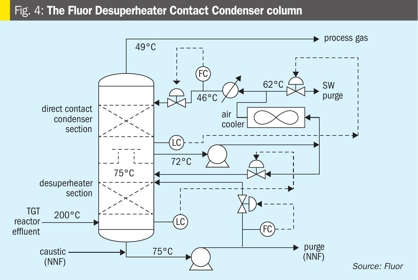
The reactor effluent is fed to the bottom section of desuperheater contact condenser where it is adiabatically desuperheated with a circulating weak solution of buffered caustic. The circulating caustic is drawn from the bottom of the DCC and pumped with the Desuperheater Pump on flow control to the top of a bed of grid packing. The circulating caustic is saturated with sulphide and carbonate and has a normal pH of about 9.5 at operating temperature. Fresh and dilute caustic solution is periodically introduced by the operator via a manual throttling valve as needed. The caustic solution is buffered, as dissolved H2S and CO2 from the process gas form sodium bisulphide and sodium bicarbonate in the buffered solution. The circulating buffered caustic is filtered via the desuperheater pump discharge filter.
A slipstream of spent caustic is periodically discharged via the desuperheater pump when determined by the operator as needed to ensure normal pH is maintained. The circulating caustic solution protects against SO2 breakthrough to the downstream sections. Water saturated process gas flows from the bottom section to two bubble cap trays to wash any entrained caustic from the vapour. The bubble cap trays are used in this section because it operates in a region with a very high gas-to-liquid ratio, making it unsuitable for any other tray or packing type
Process gas then flows through a chimney tray to the upper section in the DCC where it is cooled, and water vapour is condensed by counter-current direct contact with cooled circulating water in a bed of random packing. Water is circulated with the contact condenser pump, which draws liquid from the chimney tray below the top packed section. The circulating water is cooled in the forced draft contact condenser air cooler and water trim cooler (if applied) and returned to the column above the top packed bed on flow control.
A small amount of condensed water recovered in the top section is sent to the top bubble cap tray on bottom section level control. Condensed process water with low concentrations of H2S and CO2 is sent to the sour water system on chimney tray level control.
Conclusion
SO2 breakthrough has the potential to wreak havoc in a SRU-TGT, depending on the extent of the breakthrough. Typically, the first response to tackle this is to address the “symptom” of the lowering of the pH in the quench water circuit. Neutralising agents (ammonia or caustic) are injected or dosed to bring the pH back to normal values and in many cases due to delayed action from the operator causes significant damage to the downstream amine system. Fluor provides a design which provides sufficient time for the operator to prevent SO2 from reaching the downstream amine system. However, this does not address the real cause and does not provide a “cure” to this condition.
It is important to find out the real cause for this condition. Continuous monitoring of key operating parameters has the potential to reduce and even eliminate the chances of any SO2 breakthrough in the unit, thus providing longer run lengths and longer operating lives for SRU.