Nitrogen+Syngas 391 Sep-Oct 2024

30 September 2024
How to solve stripper efficiency issues (part 2)
Part 1 of this series on stripper efficiency issues provided a brief history of the CO2 stripping process and discussed how the invention of the HP CO2 scrubber back in the 1960s revolutionised urea technology. In part 2 we take a look at how high liquid load can affect stripper efficiency.
A high stripper efficiency is most critical in urea plants with a CO2 high pressure stripper and no medium pressure recirculation section, like in most Stamicarbon stripping plants. In those plants, a lower stripper efficiency has an immediate impact on the pressure in the low pressure recirculation section.
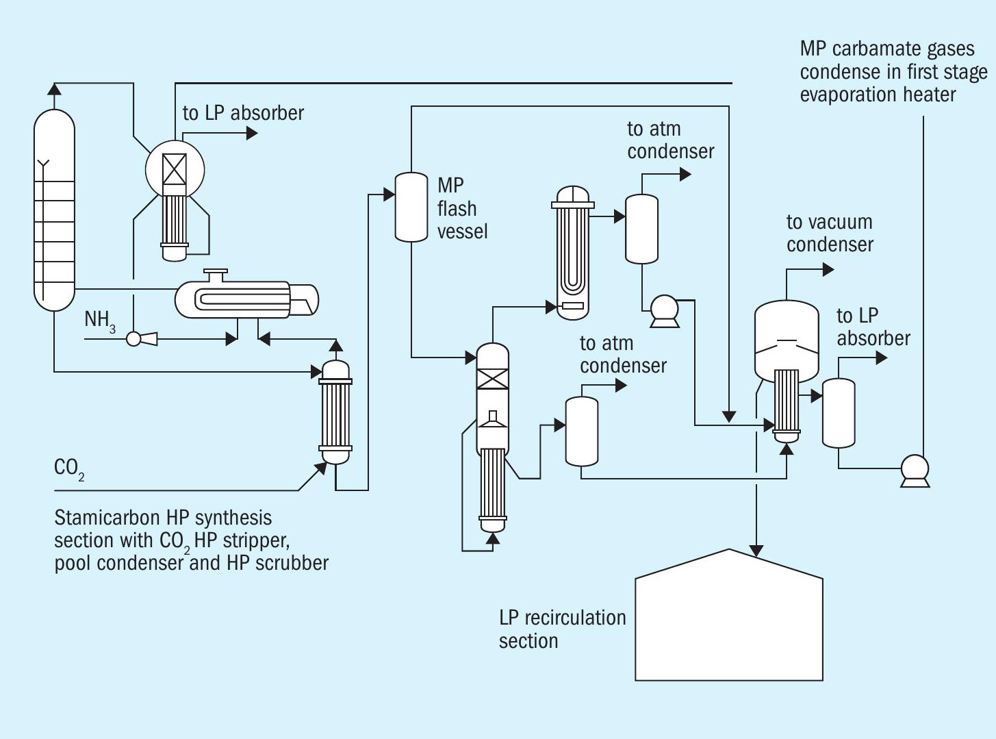
Recently, Stamicarbon introduced its LAUNCH MELT Flash technology, featuring a medium pressure vessel between the CO2 high pressure stripper and the low pressure recirculation section (see Fig. 1). With this configuration one can accept a lower stripper efficiency (for example, 70% instead of 80%) taking advantage of the lower steam consumption of the stripper (some 100 kg/tonne) and more operating flexibility for the load to the recirculation section.
With this configuration one can accept a lower stripper efficiency of 80% which can be realised with an effective tube length of 6 m. Chiyoda, one of Stamicarbon’s approved EPC contractors chose an effective tube length of 8 m, which resulted in a design stripper efficiency of 82%.
Fig. 2 shows the general scheme of a CO2 stripper. In a CO2 high pressure stripper, the liquid from the urea reactor flows as a falling film inside the tube from the top of the tubes to the bottom, while CO2 enters the bottom of the stripper and flows upwards. At the same time medium pressure steam (20-23 bar) heats the tubes from the shell side.
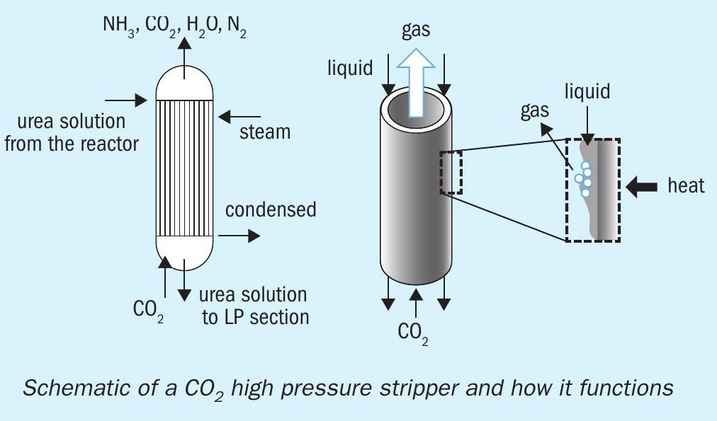
Fig. 3 shows the temperature profile of a CO2 stripper and a NH3 stripper.
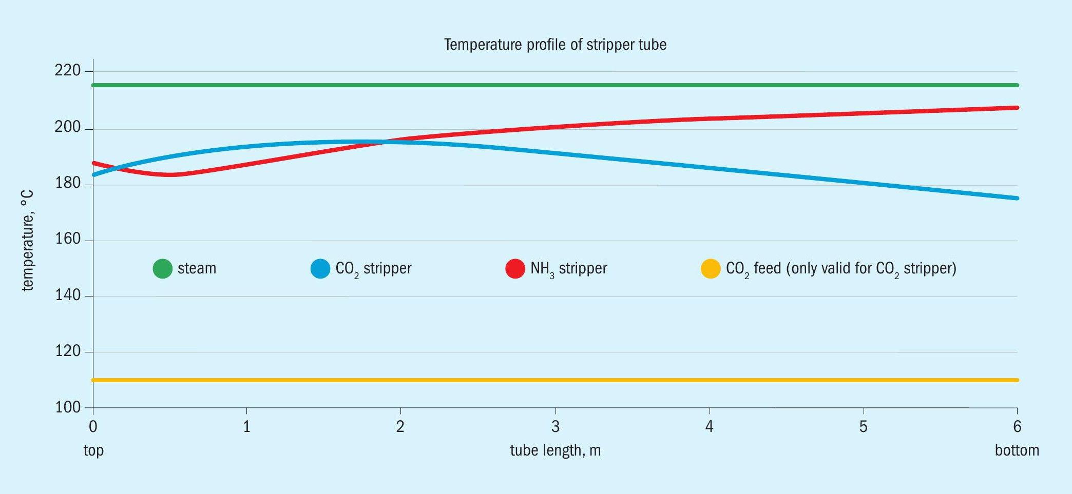
One can see that in a CO2 stripper the maximum temperatures exist in the top three meters of the tubes. This is the reason that Stamicarbon advises the measurement of corrosion rates only in this part of the tubes as the corrosion rates are highest here. One can also see that in an NH3 stripper the temperatures are highest in the bottom of the tubes and that the temperatures here are higher than in a CO2 stripper resulting in the use of titanium and zirconium in NH3 strippers.
As indicated in Part 1, there are several causes for actual stripper efficiency being lower than design. Here we discuss high liquid load.
High liquid load
As previously mentioned, in a CO2 stripper, the reactor outlet solution flows as a falling film inside the tubes from the top to the bottom. The falling film facilitates the dissociation of liquid ammonium carbamate into its two gaseous components, carbon dioxide and ammonia, and leads to the benefit of a low residence time, which minimises the formation of unwanted biuret and urea hydrolysis reactions.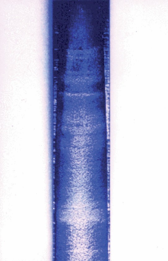
The CO2 feed flowing from the bottom to the top plus the heat from the shell side facilitates the dissociation of the ammonium carbamate still present in the solution leaving the reactor into carbon dioxide and ammonia gas. Note that hardly any water, which is also present in the reactor outlet solution, will evaporate. In the actual stripper tubes, almost half of the liquid introduced in the top is evaporated, the gas and liquid loads are much greater at the top than at the bottom. This means that flooding will occur first in the top of the tubes. At a reactor outlet solution temperature of 183°C and a pressure of 140 bar, the flooding limit in a 1-inch tube is found to be 145 kg of solution per hour. In practice, an upper limit of 70% of this value is applied. [Source: IFS Proceedings no. 166]
At a certain load the falling film will break off the tube wall and flooding will start. It is important for every urea plant to know at which plant load the stripper shows flooding because above that plant load the stripper efficiency will be lower, leading to more ammonia in the stripper bottom outlet, leading to higher temperatures of that stream and more gas to the low pressure recirculation section. The pressure in the recirculation section will increase and more carbamate needs to be recycled, leading to an overall lower performance of the urea plant. A sudden temperature increase of the stripper bottom temperature, e.g. 3-4°C in 15 minutes, is a clear indication that the flooding limit of the stripper has been reached.
Even more critical when reaching the flooding limit is the maldistribution of the liquid from the urea reactor over all the tubes. A stripper tube which receives too much liquid and shows flooding behaviour can experience active corrosion with significant high corrosion rates and a possible tube rupture in case the applied material of construction is an austenitic stainless steel. Liquid containing ammonium carbamate should and normally does contain sufficient oxygen to assure passive corrosion (max 0.1 mm/year corrosion rate) and not active corrosion (20-30 mm/year corrosion rates). But a stripper tube under flooding condition may contain liquid which has a long residence time in the tube and due to the passive corrosion rates the available oxygen may get depleted leading to active corrosion with significant higher corrosion rates, resulting finally in a tube rupture as shown in the picture on page 16. One can see the thinning of the tube wall thickness at the top compared to the bottom of the picture which results from the higher active corrosion rates.
A tube rupture is troublesome for the urea plant operators as the entire solution present in the high pressure synthesis section will flow through the ruptured tube. Thus it is very important that flooding of a stripper with 25-22-2 austenitic stainless steel tubes should be avoided. A stripper with Safurex super-duplex tubes has a significant benefit as active corrosion has never been seen with this material.
It is interesting to note that the internal surface of the tube is related to the flooding limit in a linear way. And as the internal diameter and thus also the internal surface increases in time due to the unavoidable passive corrosion rates, during its lifetime, a CO2 high pressure stripper will show an increasing flooding limit. For example, a stripper may reach its flooding limit at 110% plant load when it is new and 120% plant load at its end of lifetime conditions. As the CO2 high pressure stripper is typically one of the major bottlenecks in a urea plant, it is recommended to always replace the stripper by a larger one with more tubes when it reaches end of lifetime.