Nitrogen+Syngas 366 Jul-Aug 2020
31 July 2020
Process gas boilers with bypass for steam methane reformers
HEAT EXCHANGERS
Process gas boilers with bypass for steam methane reformers
Process gas boilers with an internal bypass system are an important type of shell-and-tube heat exchanger installed in steam methane reforming units. For decades, two traditional designs have dominated the market: the “hot” and “cold” bypass process gas boiler. Today, a third option based on a new design concept is available: the “bayonet” bypass process gas boiler, with process and mechanical features that can provide superior performance, lower opex and improved reliability. G. Manenti of Alfa Laval Olmi SpA discusses the design and operating principles of the different designs.
Process gas boilers are a special type of shell-and-tube heat exchanger installed in hydrogen, ammonia and methanol plants for cooling hot process gas discharged from steam methane refoming (SMR) units. For instance, process gas boilers installed in ammonia plants receive the gas at 950-1,050°C and 3-4 MPa(a) and cool it down to 350-550°C by means of high-pressure boiling water. Due to the severe operating conditions and demanding process performance, process gas boilers are critical equipment for SMR units.
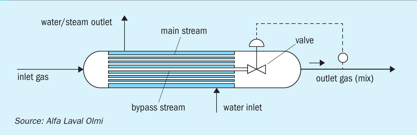
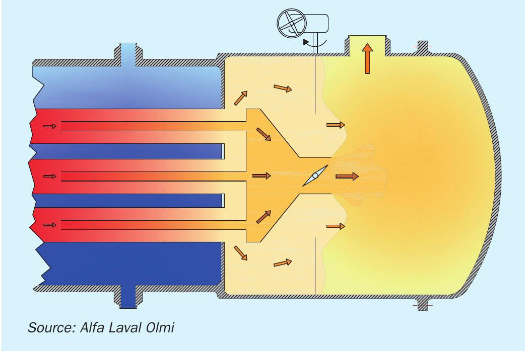
Frequently, control of the process gas temperature at the process gas boiler outlet is an essential requirement: the process gas boiler must be designed so that, at different operating loads and/or fouling levels, the outlet gas temperature is kept at a target value. Boilers are then equipped with a bypass system, mostly installed inside the boiler body. Conceptually, the hot process gas flowing in the process gas boiler is split into main and bypass streams (Fig. 1). The main stream exchanges a large amount of heat with the cooling boiling water and is therefore cooled down; on the contrary, the bypass stream has a reduced or negligible heat exchange and therefore it is only partially or marginally cooled. The two streams, at different temperatures, are then recombined before leaving the process gas boiler. Since the flow rate of the two streams is regulated by means of an internal valve(s) assembly, the overall heat exchange across the process gas boiler can be controlled. The internal regulating assembly, comprising moving parts, make process gas boilers in effect a singular heat exchanger.
Today, two state-of-the-art technologies for process gas boilers with internal bypass are available: the so-called “hot” and “cold” bypass. Both technologies have been used for decades and have proved to be reliable and effective; yet, each one suffers from specific limitations as well.
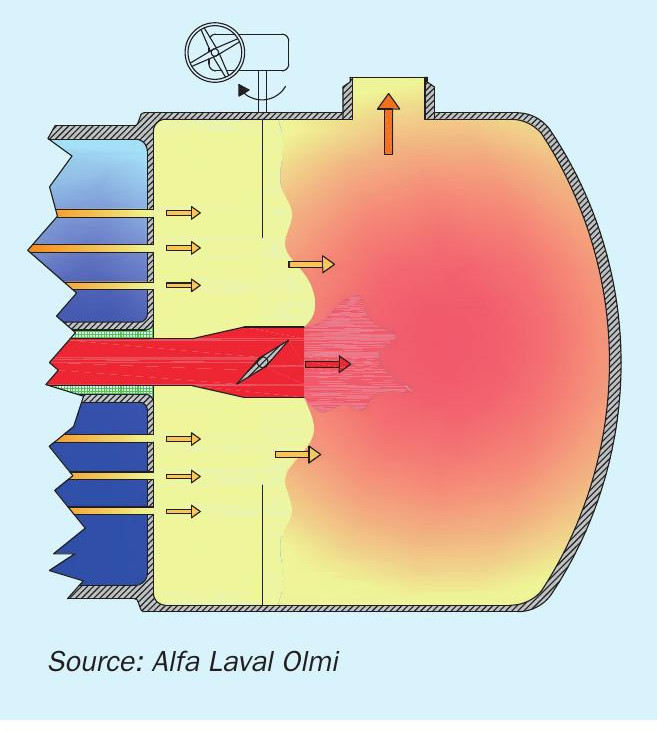
The “hot” bypass dates back to the 1960s1 . It comprises a single large pipe installed in the tube bundle, a regulating valve(s) assembly installed in the outlet channel and an external actuator (Fig. 2). The pipe is internally insulated to protect it from overheating; the bypass valve is installed at the outlet of the pipe. The bypass pipe carries the hot gas from the inlet directly to the outlet channel with negligible heat transfer. As a result, the bypassed gas discharged into the outlet channel, through the bypass valve, is hot. This leads to some advantages:
- A limited bypass flow rate (10% to 20% max) is necessary to control the final gas outlet temperature. The bypass system is inherently designed to carry a limited gas flow rate, therefore overheating due to inadvertent bypass opening is mitigated or avoided.
- Hot metal parts in direct contact with bypassed gas are inherently protected from carburisation since the gas temperature falls outside of the upper limit of the Boudouard reaction range.
However, bypassed gas impinges on the valve assembly at high temperature. Continuous research on high nickel alloys and surface treatments are aimed at mitigating aging and extending the design life of the valve.
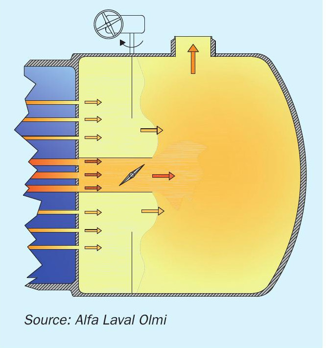
- The bypassed gas is discharged into the outlet channel, through the bypass valve, at low temperature (for instance, 370°C-430°C). The valve(s) assembly in the outlet channel then works in cold conditions; aging is avoided, design life of components is extended.
- Hot metal parts in direct contact with bypassed gas are inherently protected from carburisation since the gas temperature falls outside the lower limit of the Boudouard reaction range.
On the other hand, the low temperature of the bypassed gas imposes a large bypass flow rate to fulfil the required control range of gas outlet temperatures; consequently, the “cold” bypass system is inherently designed to carry a large gas flow rate (>50%). This design feature represents an operating and safety concern since inadvertent bypass opening/closing can lead to overheating and corrosion. On-site adjustment of the bypass range, according to operating conditions, is therefore necessary.
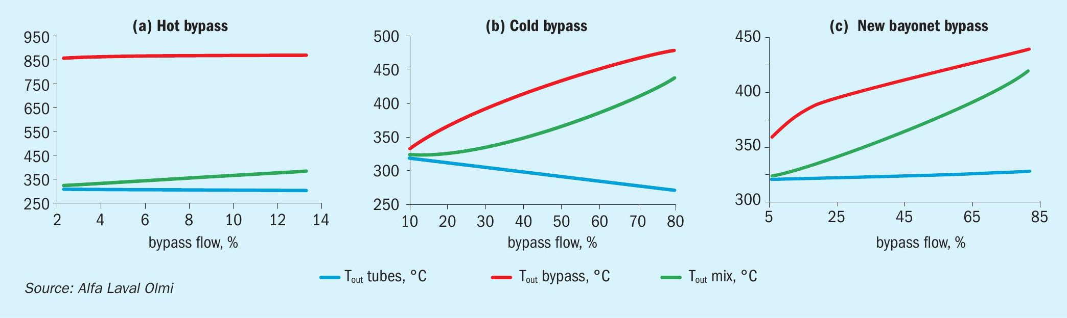
Figs 4(a) and 4(b) show typical temperature flow rate profiles for “hot” and “cold” bypass process gas boilers respectively, for an equal tube length and heat duty. These profiles are like a fingerprint of the two designs.
Process gas boiler technology
The “cold” bypass has been widely adopted among process gas boilers for hydrogen production units, whereas the older “hot” bypass is still the preferred technology for ammonia and methanol plants. Besides the operating principles and pros and cons of the different designs already mentioned, technology uptake depends on having a relevant mechanical design and technical commercial competitiveness. The main and bypass exchanging tubes installed in the “cold” bypass process gas boiler work at different thermal mechanical conditions; such conditions may also vary significantly due to the large bypass flow rate range. It should be noted that the bypass exchanging tubes are thicker than the main exchanging tubes. This leads to differential and variable thermal mechanical stresses during operation of the “cold” bypass design; as a result, stresses along the tubesheet radius are not uniform and steady, and the flatness of the tubesheet is questionable. On the contrary, the bypass pipe installed in the “hot” bypass process gas boiler works, regardless of the bypassed gas flow rate and temperature, at practically constant thermal and mechanical conditions, comparable to the boiler shell ones. The bypass pipe is large (min. DN 150) and therefore inherently thick; it is connected to the tubesheet by a specific welding joint, usually of butt-end type. On the other hand, its internal insulation has a complex design, and maintenance and inspection are time consuming.
Water-side pressure and inlet gas temperature and pressure can be considered major parameters for selecting technology. For the “cold” bypass design, the higher the water pressure, the thicker the bypass exchanging tubes; and the higher the process gas heat transfer coefficient, the larger the differential thermal mechanical conditions between the bypass and main exchanging tubes. This means that for severe operating conditions, typical of ammonia and methanol process gas boilers, the “cold” bypass is conceptually more critical and challenging from a thermal mechanical standpoint. Conversely, the “hot” bypass design is largely unaffected by pressures, temperatures, and SMR unit type; although, it should be mentioned that the maximum size of the “hot” bypass pipe could make it prohibitive for large capacity SMR units.
A new process gas boiler
As a key item of high-level equipment, process gas boilers are subject to continuous technological improvements and research. Carburisation resistant alloys represent a major field of academic and industrial research. Also, on-line monitoring and digitalisation have recently raised technological interest. However, base R&D is always aimed at improving current technological solutions for heat transfer and thermal mechanical design.
Recently, a new design of process gas boiler for SMR units was proposed by Alfa Laval Olmi SpA, named the “bayonet” bypass process gas boiler. The new boiler is the first new conceptual design in more than 25 years and brings to the market a third option besides the “hot” and “cold” designs. The “bayonet” bypass system (Fig. 5) comprises tubular bayonets inserted into the exchanging tubes from the rear end, a bypass box which connect to the bayonets, with a valve(s) assembly installed in the outlet channel, and an external actuator. The operating principle is totally different from the “hot” and “cold” bypass:
- The total amount of hot process gas is pre-cooled in the first portion of the tube bundle, then, at the bayonet tip, the gas is split into a main stream (or annulus flow – flowing in the annulus formed in between the tube and bayonet) and a bypass stream (or bayonet flow – flowing in the bayonet).
- The annulus flow provides substantial cooling along the remaining portion of the bundle since it is in direct contact with the cold tube wall, whereas the bayonet flow has limited heat transfer.
- The hotter bayonet flow is discharged into the outlet channel, through the bypass box and valve, and is then recombined with the colder annulus flow.
The characteristic temperature flow rate profile is shown in Fig. 4(c), for a boiler of the same tube length and heat duty as in Figs 4(a) and 4(b).
From a conceptual viewpoint, the “bayonet” bypass behaves like a “cold” bypass, and therefore it inherits its relevant pros and cons. The bypassed Source: gas is subject to an extensive heat transfer and therefore is discharged into the outlet channel at low temperature (for instance, 370-410°C): the bypass box and valve assembly in the outlet channel work at a low temperature, with the bayonet tip being the hottest part of the bypass system. On the other hand, the bypass system is also inherently designed to carry a large gas flow (>50%), and this leads to concerns and requires bypass adjustment as previously described. However, the new process gas boiler has additional important process and mechanical benefits:
- The gas flow rate at the tube inlets is unaffected by the bypass opening: the inlet heat flux is unaffected and the inlet thermal hydraulics are inherently steady.
- The process gas boiler is somewhat less sensitive to inadvertent bypass opening: the risk of downstream overheating is mitigated.
- The gas flowing in the annulus has a notable higher velocity (min. 150% higher) than the corresponding gas flowing in the traditional “hot” and “cold” designs, and this results in a threefold advantage:
– heat transfer rate is boosted in the portion of the boiler bundle where, typically, transfer rate is poor (low velocity portion);
– risk of fouling deposition is mitigated or eliminated where there are bayonets;
– option to use exchanging tubes of larger OD, to reduce the number of tubes.
- All exchanging tubes have equal geometry and thermal mechanical working conditions, therefore:
– stresses along tubesheet radius are uniform and invariant to bypass opening, therefore the tubesheet stays intrinsically flat,
– severe operating conditions, like high water pressure, do not affect the mechanical design of the bypass system,
– tube-to-tubesheet welds are equal and have same operating conditions,
– inlet ferrules are identical.
The installation of the bayonet into a portion of the exchanging tube has a turbocharging effect: the overall heat transfer performance is enhanced, and the process gas boiler exchanging area can be reduced by 10-25% compared to a traditional design. For a small gas-to-water temperature pinch point, the turbocharging can be very effective in reducing the tube length. Of course, the turbocharging has a cost in terms of gas pressure drop: the higher the allowable pressure drop, the more competitive the “bayonet” bypass.
Again, the mechanical design and manufacturing layout of pressure parts are remarkably simpler and more robust than traditional the “hot” and “cold” designs thanks to the uniform bundle. The bypass system is constituted of internals only and is not subject to pressure vessel code or NoBo; the bayonet bypass is just inserted into the process gas boiler body once the pressure parts are completed. For maintenance or inspection of the bypass system, a manhole or a channel cover can be selected according to the client or end user’s preference.
The new bayonet bypass process gas boiler design offers process and mechanical features which may lead to superior performance, lower opex and improved reliability. Thanks to its experience and knowhow, Alfa Laval Olmi SpA is in the position to design and supply all three process gas boiler types depending on clients’ requirements, preferences and affordability.
References