Nitrogen+Syngas

31 March 2018
Problem No. 47: Active corrosion during blocking in
This discussion is about the risks of active corrosion or failure of passivation during a blocking-in situation of the high pressure synthesis section of the urea plant. It touches on many aspects searching for a possible cause of active corrosion during such a situation. The final outcome is of significant importance for all urea plants worldwide.
Cory Holt, process engineer at CF Industries in Canada, initiates the discussion: Could anyone share their expertise with respect to urea process passivation and the possible modes of failure and has anyone ever worked at a plant where passivation has failed. Our facility has recently shown physical signs of passivation failure in our reactor although all process data shows that we had oxygen in the system and proper passivation. We recently have come out of a scheduled shutdown and upon starting up we had a higher than normal N/C ratio as well as periods where we sat full in our HP loop while maintenance worked on some start-up issues.
Mark Brouwer of UreaKnowHow.com, the Netherlands, asks for some further clarification: Did you block in the synthesis while solving the start-up issues? If so, for how long and how many times and what was the interval between the block-ins?
Cory replies: There were a couple of issues and we attempted to start up three or four times. The longest period was a 22 hour period at which we know our N/C ratio was greater than 4.
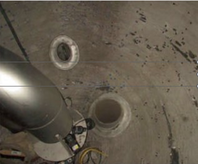
For the first start-up we were nine hours into start-up when we went down for six hours. Then we attempted the second start-up over a three hour period and went down for five hours. The third start-up was over a two hour period and then we went down for 22 hours. We attempted the fourth start-up over a 22 hour period when we were again forced to go down due to our leak detection system ringing in exposing a leak. When we shut down to look at the leak we realised our vessel had been stripped of its regular iron oxide coating due to passivation. Upon vessel entry we realised we had many more pinholes and advised that they were a result of active corrosion at accelerated rates. This tends to point a finger at loss of passivation but our DCS trends show that we had oxygen in our system for the duration of the start-ups.
We are wondering if our high N/C ratio had something to do with losing passivation in the reactor or if it was consumed by a contaminant, perhaps something from turnaround cleanings.
Mark provides his experience: I’ve never heard that a high N/C ratio causes active corrosion. On the contrary, Saipem states a high N/C ratio reduces corrosion rates.
Blocking in is always a situation where hot carbamate solution is in a vessel and no new oxygen can enter. The existing oxygen will be consumed by the normal passive corrosion and a chromium oxide layer will form as a passive layer. When the blocking in time is too long the amount of oxygen becomes insufficient and active corrosion starts.
Stamicarbon and Saipem claim that blocking in times should be limited to maximum 72 hours.
Your remark of a contaminant consuming oxygen is interesting, although I have never heard of that phenomenon.
Does anybody else have similar experiences of blocking in right after start up and seeing active corrosion?
To see many new pinholes after such a short time seems strange to me. One should realise that a pinhole itself is anyhow an area of low oxygen refreshment even if the bulk liquid has sufficient oxygen. That its growth is accelerated so much seems odd.
Further stop-start and start-stop situations cause big stresses on the liner due to temperature differences between the liner and the carbon steel wall and weaker areas could create a leak.
Cory responds: Thank you for your expertise, it does allow us to eliminate our N/C ratio concern. The active corrosion is odd to us too but we had the reactor inspected and did some repairs during the turnaround which would not have missed these pin holes. We have found between 30 to 50 significant pin holes in just the bottom head alone and are inspecting the remaining zones now.
Muhammad Farooq of SABIC-SAFCO in Saudi Arabia asks some further questions:
- What is the material of the liner of your urea reactor and how long has it been in operation?
- What is the inspection frequency period?
- What procedure did you apply for the repair of previous pin holes and is it your practice that defects are removed first time? Did you monitor the liner thickness ever year?
- What is your feeding sequence and ammonia feeding temperature at start up?
- Did you analyse the temperature profile in a recent start-up of the urea reactor, especially at the reactor bottom?
Cory answers Muhammad’s questions:
- The lining material is 316-SS and when we have made repairs we use 25-22-2 SS as a weld material after grinding out the cavity. This liner is approx. 35 years old and the reactor was scheduled for re-lining in 2015.
- We inspect on every scheduled maintenance outage which is every three to four years but due to other maintenance issues this has been every two years lately.
- Repairs are always done as explained in my first point. As mentioned in the previous discussion, we were just coming out of a turnaround where minor repairs were done and we had Stamicarbon do a pre-start-up inspection. They are currently doing our inspections now as well.
- We usually warm the HP loop by feeding CO2 and steam (CO2 having oxygen from air blowers @ 0.6 vol-%) until we achieve 270°F (132°C) at the top of the reactor. Then we feed in ammonia.
- Yes, we looked at the temperature profile and actually realised we achieved the fastest heat up we have ever seen. Usually the heat up takes three to four hours but we almost achieved 270°F (132°C) within two hours. We are currently trying to prove whether the instrumentation was working properly as we cannot explain the accelerated temperature increase.
We are currently looking at our DCS data to see if during our start-up attempts and block-ins we mismanaged the pulling of feed sequence or if somehow our instrumentation failed to show us loss of actual air. Initial data pulled has shown we were adding the right amount of air to our CO2.
A question arising from this is whether circulating ammonia through the HP loop without CO2 (which means no oxygen) may have somehow disrupted the passivation layer?
Muhammd Kashif Naseem of SABIC in Saudi Arabia shares his experience: I think your heating rate is very high. Keep it around 30°C/hour and use fresh air instead of a mixture CO2/air for heating time passivation. I think the CO2 mixture during heating with steam as water is creating the corrosion issues.
Both materials SS316-L UG and 25-22-2 SS are OK. Your licensor can advise you further with regard to materials.
We also operate a plant that is 30 years old. Every two years we inspect the plant and replace the liner material in the areas with the highest corrosion rates (vapour section). The original material was SS316-L UG and the top portion has been relined with 25-22-2 SS.
Cory comes back: I agree that the heat up rate is too high. We usually stay at around 30 to 50°F for the heat up. With our process it is impossible to have the heat up rate that we had with just steam or CO2 and we are not sure why it got as high as it did. We have our vendor involved to find out how we reached such a high heat up rate (almost 107°F/hour). We looked at our instrumentation to see if it was functioning fine and it looks like it was.
Not sure if the heat up rate has anything to do with active corrosion. All of our process data shows we had passivation (oxygen). We are wondering if we had a contaminant that gave us an exothermic reaction that affected the passivation and give us a lot of heat?
Mark shares his experience and asks some further questions: Heat can be generated via condensation of steam and by the formation of carbamate from NH3 and CO2. What are the pressures where you see a high temperature increase? Do you see a temperature increase at all thermowells or only certain ones? I do not see that circulating ammonia without CO2 would cause problems with the passive layer. Is there any chance that chlorides or sulphur could have entered the synthesis? These components cause problems to the passivation layer.
Cory replies: When the temperature took off, the loop pressure was roughly 1.4 bar (80°F/24°C) and increased to approx. 4 bar (240°F/115°C) within 1.5 hours. We have seen the temperature increase on all four thermowells in the reactor as well as the overhead gas line. The CO2 flow was around 1,130 kg/h during this time. So far we have not found any indication of chloride or sulphur contamination.
Mark continues the discussion: Do you have graphs of the various temperatures versus time?
Passivation of stainless steels can be hindered by heat tints (result of welding) or by fouling caused by corrosion product (iron and chromium oxides) or metal parts (grinding).
Once active corrosion of carbamate starts it cannot be stopped and one needs to stop the plant, drain and re-passivate the surface.
Is it possible that heat tints and/or fouling is playing a role?
Essa Norozipour of Khorasan Petrochemical Company in Iran shares his experience: All equipment in the synthesis section requires at least two hours of oxygen injection for passivation. If the plant is started and then stopped before two hours of passivation has been carried out, the synthesis cannot be blocked in and must be drained completely and re-passivated. Did you check the interval of the start-up, shutdown and block in of your plant?
Cory replies: We do have trends, I have been trending every reliant DCS tag looking for discrepancies.
It may be possible that we have had grinding or welding contaminants as we did do some repairs during the scheduled turnaround before these start-up events. This has been discussed and we are looking into it. What baffles us still is the significant heat up rate. We have looked at the time intervals and discussed them with our vendor and everything looks like it was in place and confirmed with our DCS data showing we had oxygen.
Mark responds: It is not easy to control the temperature rise at the beginning. I believe this occurs in other plants where the temperature increase is higher than the recommended 30°C/h.
Muhammad Farooq shares his experience: I also agree that the temperature rise during start-up when the pressure is 20 bar and temperature is more than 100°C (after passivation and heating) increases quickly especially during the first hour. However it is normal start-up behaviour in many plants.
My other observations are that the reactor liner is very old and needs early replacement.
The issue of passivation and heating of the synthesis loop needs to be sorted out with the vendor’s help. It is not clear what the impact is on other equipment such as the stripper, carbamate condenser and scrubber.
The inspection frequency needs to increased to once per year.
Note: This above case was presented during the licensor’s conference and the lessons learned are:
- Any time the urea plant goes down and the loop is not drained, monitor the vessel temperatures for any heat increases. If the temperatures increase by more than 20°F, the synthesis loop must be drained immediately.
- Ensure positive isolation of CO2 when the loop is blocked in by monitoring the loop pressure. If the loop pressure starts increasing, and the temperature in the vessel remains stable, operators can investigate according to their own judgment. If the vessel temperatures also start increasing, the loop must be drained down as above.
- Ensure operators close the isolation valve downstream of HIC- 1201 (CO2 inlet to reactor).
Modify the urea plant start-up procedure to include lab analysis of the stripper bottoms for metals found in the stainless steel liner, specifically Fe, Ni, and Cr. The first sample must be taken within 12 hours of start-up and the second 24 hours later. If the values are stable or decreasing, no action is required. If the values are increasing, the plant will be shut down and drained.