Nitrogen+Syngas 396 Jul-Aug 2025
22 September 2025
Problem No. 75: Reverse rotation of the CO2 compressor
Reverse rotation of an inline four-stage centrifugal CO2 compressor is an unwanted phenomenon which sometimes occurs in urea plants. Reverse rotation can lead to damage to the internals of the CO2 compressor and an expected outage. This discussion shares experiences and provides suggestion on how to avoid reverse rotation of the CO2 compressor.

Miss Bhawna of NFL in India kicks off this round table discussion: What harm can reverse rotation of the CO2compressor do and how it can be prevented?
Niranjan Murthyp of Mangalore Chemicals and Fertilizers in India asks for further clarification: First let us know which type of compressor and why it is rotating in reverse direction?
Bhawna replies: When the centrifugal compressor tripped the higher pressure at the discharge side of the centrifugal compressor can overcome the lower pressure that is always present at the suction side of the compressor. In this situation reverse flow is possible. Some plants have reported reverse rotation phenomena in the CO2 centrifugal compressors.
Serpoush of Shiraz Petrochemical Complex in Iran contributes to the discussion with his valuable experience: In the CO2 compressor outlet, three valves (check valve, shutdown valve and bleed valve) may stop the reverse flow by depressurising the compressor discharge pipe line, and in doing so preventing reverse rotation. The shutdown valve and bleed valve are automatic valves and are located in the discharge outlet pipe line and before the non-return valve that is actuated by trip signal(s).
Ajay from CCFL in India shares his opinion: Reverse rotation of the compressor may damage internals such as bearings, seals etc.
Mark Brouwer of UreaKnowHow.com in the Netherlands joins the discussion: CO2compressors typically have four reverse flow protections in its discharge line:
1. Trip shut-off valve
2. Vertical non-return valve (NRV)
3. Horizontal non-return valve
4. Pressure release valve
But reverse gas flow through the compressor is possible, caused either by passing of the level control valve of the 3rd separator or by passing of the non-return valve at the 3rd suction. A compressor is not designed for reverse rotation, this phenomenon may cause damage to the bearings and misalignment. To overcome this problem, the pressure release can be linked (open) with the trip logic of the compressor.
Pawan Verma of IFFCO in India also joins the discussion: Reverse gas flow through the CO2compressor is only possible when the NRV provided in compressor is passing and the size of the vent control valve provided in the final discharge line and at the 3rd discharge line is insufficient to discharge the volumes trapped.
The problem of reverse flow may be overcome by regular servicing of the non-return valves and by increasing the vent valve size provided in the compressor.
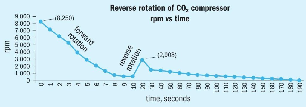
Prem Baboo, Expert of UreaKnowHow.com shares his valuable expertise and experience: We have also experienced reverse rotation in our urea line-II in 1997. When the centrifugal compressor tripped, the higher pressure at the discharge side of the centrifugal compressor was able to overcome the lower pressure that is always present at the suction side of the compressor. This is a situation that possibly creates reverse flow. Some plants have reported reverse rotation phenomena in the CO2centrifugal compressor. Reverse rotation is an unwanted phenomenon in a centrifugal machine as it is always associated with severe radial vibration and axial displacement which may lead to damage of the bearings and rubbing of seals with the stationary components. Bearing failure is a definite possibility. Seals are not rated for this rotational speed. Internal compressor components may become dislodged. There is a high possibility of vibration damage in the reverse position. Coupling is rated for the rotational speed as long as the train does not become energised. Rotor over speed can cause over stressing in the bearing (journal/thrust) causing fit to loosen or worsen.
To safeguard against reverse rotation in CO2 compressors the following changes are proposed: During shutdown the anti surge valve (HV-62) provided from the 4th stage discharge to the 1st stage suction and the 2nd stage vent (HV-61) provided from the 2nd stage discharge to the atmosphere should be open. In addition, HV-63 provided from the 2nd stage discharge to the 1st stage suction logic should be changed so that it opens through the solenoid during tripping. The timing of opening of HV-61 should be decreased. In addition, the final discharge vent (PV-3) logic should be changed to open it during tripping of machine. The capacity of the CV should be on the higher side.
Mark comes back: Reverse rotation can be avoided by installing kick back from casing to casing and installing the non-return valves at discharge of final stage.
Syed Salman of Agritech in Pakistan shares his valuable experience: In my view, reverse movement of the shaft is only possible in case of high poly-tropic/discharge head or in simple words “surging”. Once the compressor is tripped due to actuation of the surge counter security, reverse movement is almost impossible because:
• Kick backs will automatically open and equalise the pressure between the suction and discharge ends of compressors.
• Generally auto valves at the compressor discharge open automatically to relieve the discharge line.
Additional protection in terms of non-return valves is also available.
Gas within the compressor at its discharge ends does not have much force to first stop the compressor nor much capability to provide the force required for meeting the requirement of the starting torque. However in case of reverse rotation, an important point is the speed of the compressor i.e. at high speeds it will definitely causes vibrations and damage to seals.
Bhawa comes back: Please refer to the detailed paper by Mr Gautam and Mr Panda of IFFCO Phulpur about the case of reverse rotation of the rotor of a centrifugal CO2 compressor. A centrifugal machine experiences reverse torque due to reverse flow of high pressure fluid from the discharge side to the suction side through the rotor as soon as the machine is tripped at full load. But reverse rotation is an unwanted phenomenon as it is always associated with severe radial vibration and axial displacement of the rotor which may lead to damage to the bearings and rubbing of seals with the stationary components.
This paper describes how the reverse rotation of the CO2 compressor trains provided in phase-II urea plants at Phulpur was diagnosed by the analysis of post trip data picked up by Data Manager-2000 and the step-by-step in-house approach to find the solution. https://ureaknowhow.com/1997-gautam-iffco-phulpurreverse-rotation-co2-compressor/
And a similar case is described by Prem Baboo: Reverse rotation phenomenon in the CO2 compressors during stopping of turbine was observed in 1997. In our Vijaipur unit, CO2 compressors were installed for four streams of the urea plant namely (11, 21, 31, and 41). CO2 compressors are of BHEL (India) design. In our case line-I urea plant (11, 21 streams) were commissioned in 1987 whereas line-II urea (31, 41 streams) were commissioned in 1997. Reverse rotation is an unwanted phenomenon as it is always associated with severe radial vibration and axial displacement of the rotor which may lead to damage to the bearings and rubbing of seals with the stationary components.
This paper describes how the reverse rotation of CO2 compressor trains provided in line-II urea plants at Vijaipur was diagnosed by the analysis of post trip data picked up by Data Manager and the in-house approach to find the solution. https://ureaknowhow.com/forums/topic/reverse-rotation-of-co2compressor/#post-120694
Syed replies: In my understanding, the case study you have shared is self-explanatory. Actually, it is a sort of investigation report based on PDCA cycle, revealing some design constraints regarding relieving the 3rd stage pressure through the 4th stage and uneven depressurisation of inter-stage piping and equipment. This uneven depressurisation generates enough torque to be capable of rotating the shaft in the reverse direction. Latterly, the problem was resolved by instantaneous opening of the “2-1” recycle valve with the application of a solenoid valve along with the 2nd stage vent and by incorporating some modifications in the interlock system. In my view, there should be no reverse rotation in the compressor if there is no design constraint. Anti-surge, vent and non-return valves are provided in order to prevent such problems in the worst conditions.
Let me share our experience with you regarding design constraint. We have a turbine driven centrifugal compressor comprising of LP and HP casing and each casing consists of 2 stages installed on CO2 service. The original equipment manufacturer is MHI, Japan. The anti-surge system is provided by CCC, USA consisting of 1-1, 2-1 and 4-3 kick backs. The machine is designed to raise the pressure from 0.9 kg/cm2.g to 178 kg/cm2.g under normal operating conditions. A few years before, we were shutting down the plant in an emergency due to some problems in our national gas headers. The compressor tripped due to actuation of low pressure security at the first suction. This was surprising because everything was going smoothly as per our standard operating procedures. Latterly it was found that 2-1 kick back opens rapidly letting down the pressure from 44 ~ 0.9 kg/cm2.g in order to meet the flow requirements at the 1st suction. This sudden opening results in formation of dry ice, even after the injection of hot gas and restricts the flow passage downstream of the kick back. This design constraint was resolved by some counteractive measures.
Sandeer Kochar of GNFC in India shares his valuable experiences: We, at GNFC Bharuch, are facing the same problem of reverse rotation in the CO2compressor. Based on Prem Baboo’s technical paper and after consultation with the OEM BHEL, opening of the 2nd stage recycle control valve (HC-1) has been incorporated into the machine trip logics. However, after this modification, we are still experiencing reverse rotation. Our control valve response timings are as follows:
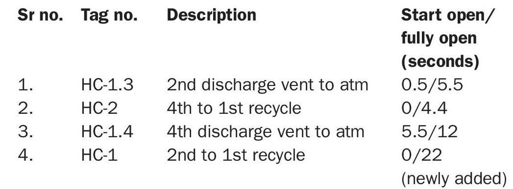
Recycle from the 2nd stage discharge to the 1st suction takes 22 seconds to fully open. Can reducing this time solve our problem? If yes, then how many seconds are needed to fully open? Our plant operates at 40,000 Nm3/hr CO2, whereas the control valve has a nominal capacity of 30,200 Nm3/hr. Can closing of the CO2 inlet valve on compressor tripping solve the reverse rotation problem?