Nitrogen+Syngas

7 August 2025
Problem No. 53: Restriction orifices in VOP exchangers and their influence on biuret formation
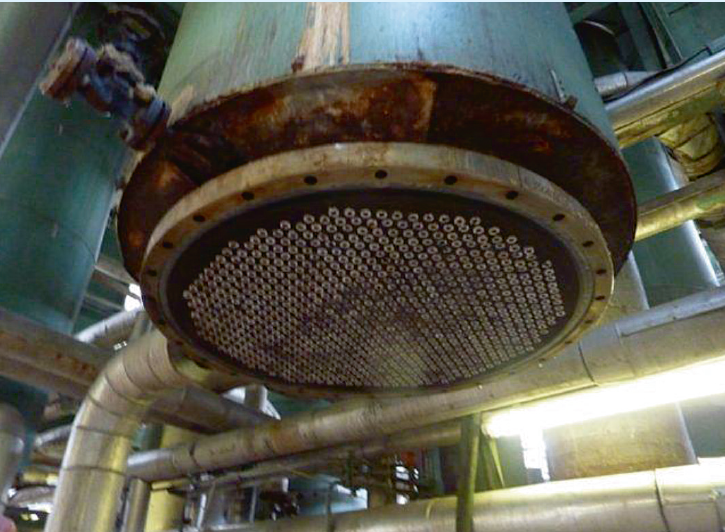
Vertical one pass (VOP) heat exchangers are used in many urea plants. As the residence time in these heat exchangers is small, unwanted side reactions like biuret formation and hydrolysis of urea are limited. Liquid enters the tubes of the heat exchanger at the bottom side via a control valve. Due to the pressure drop over this control valve some flashing will occur. Furthermore the heat input from the shell side will also result in gas formation. The gas causes a turbulent environment at the tube side increasing the heat transfer co-efficient.
Some phenomena, however, can limit or reduce the performance of these heat exchangers. One problem can be bad distribution of the inlet liquid/gas mixture over the tubes, with some tubes receiving more feed than others, recirculation from the outlet to the inlet may also occur, all limiting the performance. Another problem can be fouling on the tube side, which causes limitations of the heat exchanger.
The more turbulence on the tube side of VOP heat exchangers, the higher the heat transfer coefficient, the better the performance of the heat exchanger and the lower the risk that fouling can settle on the tube side. It is common experience that orifices at the inlet of the tubes improve the distribution over all of the tubes, increase the turbulence on the tube side, reduce fouling on the tube side and thus increase the performance.
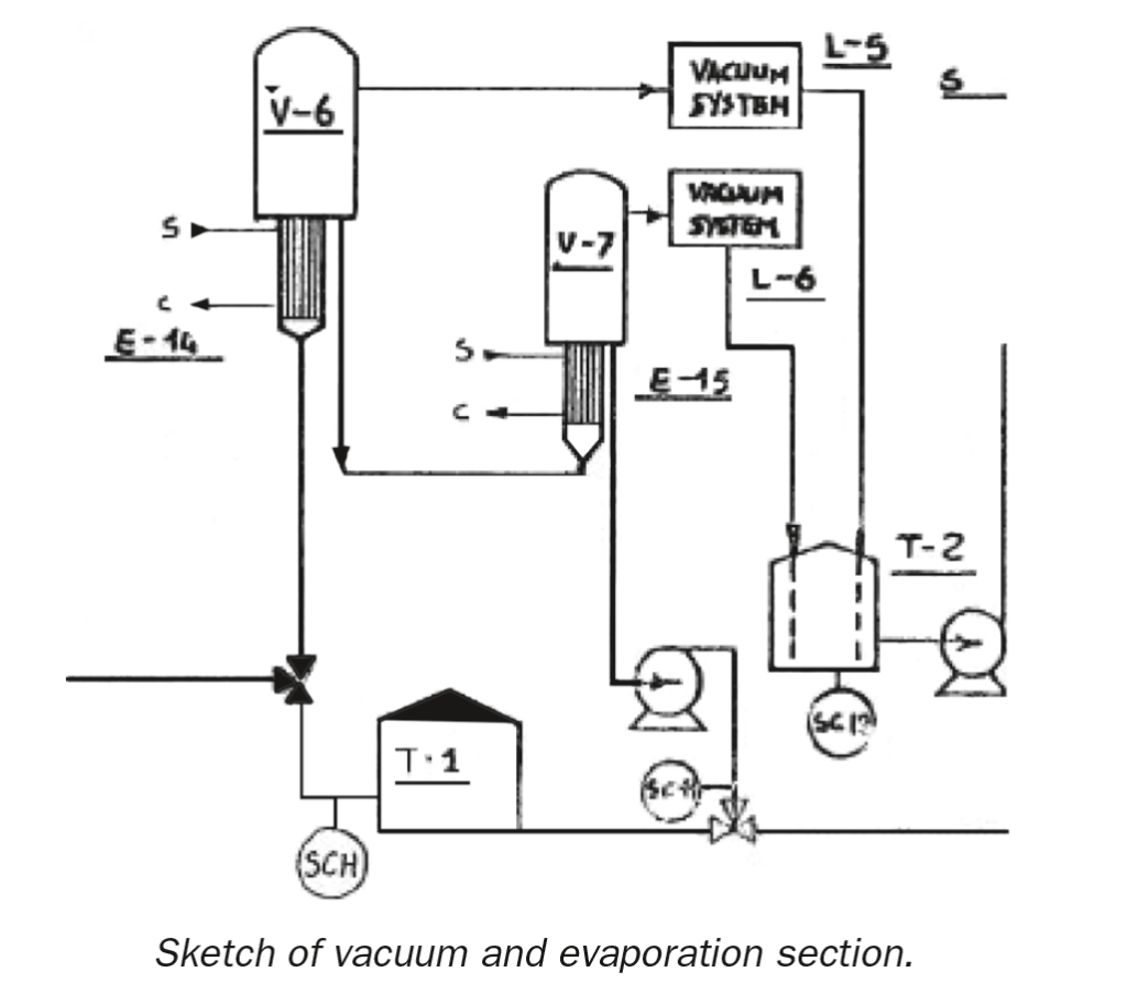
Munirm Munir of Pakarab Fertilizer in Pakistan starts the round table discussion: Can anyone share his/her experience of installation of restriction orifices in vertical one pass (VOP) evaporation heaters (E-14, E-15 or other) in a Saipem urea plant and the reduction in biuret as a result? A sketch of the vacuum and evaporation section of the plant at our site is provided.
At present, the biuret content in our final product is 1.1 w-t%. Will the installation of restriction orifices in VOP heaters E-14 and E-15 on the process side help us in reducing the biuret figure in our final product?
Prem Baboo of Dangote Fertilizers in Nigeria responds: In the urea plant I worked for previously, a control valve is provided in the steam supply to E-14 and E-15 for controlling the desired temperature of urea solution to control the biuret. In VOP heat exchangers there is a problem of flashing because the control valve is located at grade level. After that a pressure drop occurs due to the two-phases (gas and liquid) sometimes causing hammering in the vertical line.
- LMTD across vertical heat exchanger increases;
- flashing problem will be solved;
- regular and constant flow;
- two-phase (gas-liquid) problem will be solved;
- biuret can be controlled at constant plant load;
- unwanted side reaction can be controlled.
Some more suggestions: The control valve can be relocated to a position closer to the vertical heat exchanger. At variable plant load there is a fixed diameter of orifice. The orifice is suitable at constant load but at variable load, how do you manage the pressure drop with an orifice? For variable loads the control valve can be relocated near the vertical one pass heat exchanger.
Munirm replies: Actually, our plant mostly runs at constant load (i.e. 120% of 300 t/d capacity). If the restriction orifices can help us to reduce the biuret content in the product then we can go for it. Do you know of any references where restriction orifices have been installed? Maybe we can obtain some data from them regarding their performance. The control valve (LV-22) is located down L-3 (LP decomposer holder) and there is about 100 m distance between LV-22 and the E-14 inlet. I believe you mean relocating this control
valve? Will it help us to decrease biuret in our final product?
Prem continues the discussion: If you install orifices before E-14 then what is the function of the upstream control valve (LV-22)? The control valve can be relocated near to E-14 and there is no need for orifices anymore. This will help to rectify the problem.
Munirm continues: Relocation of LV-22 is probably an optimal solution. At this point, the biuret content in our final product is ~1.15 wt-%. Will we be able to achieve < 1 wt-% target with this modification? Do you know of any references?
Prem replies again: Yes, relocation of the control valve is proven, but I don’t know about the orifices. We have also relocated this control valve to the vacuum section area from the LP holder.
Munirm continues: Ok, thank you. We’ll be looking to implement this at our site.
Majid Mohammadian of OCI Nitrogen in the Netherlands joins the discussion: Restriction orifices (plugs) are mostly installed in the second stage of evaporation in the inlet of each tube which will increase the velocity, minimise the residence time and therefore reduce the biuret formation of the high temperature and high concentration urea melt.
In Stamicarbon plants the tube diameter of the evaporator heater is usually reduced to 7 mm. Please check with your licensor when selecting the diameter of the orifice plugs.
Munirm continues: The outside diameter (OD) of our VOP tubes is 3/8″. The size of the orifice is clear now but it is still unclear how much it will reduce the biuret content in a Snamprogetti urea plant. Can you share the performance improvement achieved at your plant after orifice installation?
Majid replies: If the OD is 3/8″ (9.5 mm), I don’t think the restriction orifice will be effective in your case. In our case the OD was 20 mm therefore installation of orifices could increase the velocity and reduce the biuret.
Munirm continues: The biuret in the urea melt after the 2nd stage evaporator heater and the prilled product is almost the same which indicates we cannot reduce the size of the melt line to increase velocity. We also took the following measures as operational controls to minimise the residence time, temperatures and holder levels.
- the level in the MP and LP holders is kept as low as possible;
- the pressure drop in the vacuum section is kept at 0.3 to avoid hold up;
- N/C ratio is kept at 3.5 (3.4-3.6) as per design;
- the stripper bottom temperature is maintained at around 201°C;
- the prilling bucket urea melt temperature has been reduced from 140°C to 136°C;
- diversion to the urea solution tank and recovery is avoided.
What else can we do to reduce biuret if restriction orifice are ruled out? Any suggestions?
Majid replies: One question: have you been faced with the issue of high biuret issue recently or do you want to improve it to lower than the design value?
Munirm responds: Actually, we want to improve it and bring it lower than the design value. The design value is greater than 1 wt-%.
Majid replies: As you have mentioned you have done all the required process adjustments. If you want to further reduce it to lower than the design value you have to increase the speed of the urea solution/melt or reduce the distances between the preconcentrator, evaporators and the prilling bucket.
Muhammad Kashif of SAFCO in Saudi Arabia shares his experiences: Restriction orifices are used in Stamicarbon urea plants in the rectifier heater and 2nd stage evaporator heater to reduce biuret. However a better solution with respect to mechanical maintenance and reliability is to use an orifice plate with PTFE gasket.
| This series of discussions is compiled from a selection of round table topics discussed on the UreaKnowHow.com website. UreaKnowHow.com promotes the exchange of technical information to improve the performance and safety of urea plants. A wide range of round table discussions take place in the field of process design, operations, mechanical issues, maintenance, inspection, safety, environmental concerns, and product quality for urea, ammonia, nitric acid and other fertilizers. |