Fertilizer International 526 May-Jun 2025

2 May 2025
How to revamp a urea plant
Revamps are performed to deliver production improvements at existing urea plants. While increasing capacity is the most typical objective, revamps can also cut operating costs, increase plant availability and reduce environmental impacts. In this article, Marc Wieschalla of thyssenkrupp Uhde provides an overview of some of the main revamp options – from an engineering, procurement and construction (EPC) perspective.
Introduction
Plant revamps deliver improvements by changing, designing or making something differently. Applied to urea plants, revamps can have very different objectives with the range of improvements including:
- Increasing production capacity
- Utilising CO2 sources or surplus ammonia
- Cutting operating costs, e.g., by reducing energy consumption
- Reducing environmental impacts, e.g., by cutting emissions
- Increasing plant availability and reliability, e.g., through the use of improved construction materials or state-of-the art technologies
- Production of additional urea products – such as AdBlue® or melamine
- Improving operability, e.g., by modernising the control system.
Raising production capacity is the most common urea plant revamp goal, simply because the additional output delivers a rapid payback on investment. There are three main revamping options for increasing capacity:
- Melt plant revamp
- Granulation plant revamp
- Providing additional CO2 to the synthesis process (see box).
thyssenkrupp Uhde GmbH (Uhde) has more than 65 years of experience in the engineering, supply of equipment and commissioning of urea plants with more than 120 plants built worldwide. Uhde works with Stamicarbon, the world’s leading licensor for urea synthesis, this making an ideal combination with thyssenkrupp Uhde Fertilizer Technology (tk UFT), the preferred licensor for urea granulation. This enables Uhde to offers revamps for both urea synthesis and granulation units, based on Stamicarbon and tk UFT process design packages, even when their original technologies are different.

How to approach a revamp
There are basically four steps in approaching a urea plant revamp (Figure 1).
Revamp study (Steps 1a and 1b). The initial phase of the revamp starts with a study to determine the process concept and provide an initial cost estimate (1a). The EPC contractor must be involved at this phase – if a more precise cost estimate is required (1b). Detailed concepts can then be considered. These need to answer several questions, such as:
• Where do the required utilities come from – and how can the higher quantities of raw materials required be made available at source?
• Is there enough space available to place new structures?
• How can the revamp be carried out to minimise downtime?
Basic engineering (Step 2). In the second phase, the basic engineering (BE) is carried out according to the licensor’s process design package (PDP) and concepts provided by the EPC contractor. Initial equipment – proprietary equipment, critical equipment and equipment with long lead times – is also purchased during this phase.
Detail engineering (Step 3). This third phase is usually performed by the EPC contractor with all the remaining equipment purchased. The client can also carry out agreed parts of the purchasing in this phase.
Construction, commissioning and start up (Step 4). The revamp ends with the construction and commissioning of the new parts of the plant. While the contractor usually carries out construction, there are more options for commissioning. The customer may only need advisory services, for example, if very experienced. For less experienced customers, Uhde also offers complete commissioning services, provided with support from the licensor.
Revamping the melt plant
There are five basic concepts/activities for revamping the melt plant to increase capacity – as set out in Table 1:
• Debottlenecking
• More in, more out
• New/double stripper
• Medium pressure (MP) add on
• Pool condenser.
Debottlenecking can increase capacity by up to 10%. As a general rule, major equipment remains largely untouched with only the control valves, pipes and pump impellers changed or replaced. Bottlenecks can usually be identified during a plant visit – by inspecting data from the distributed control system (DCS), checking equipment datasheets and interviewing operators.
The other four melt plant revamp options shown in Table 1 can increase the original capacity by up to 100%. For these options, the involvement of the licensor is a must. The replacement or modification of static equipment is also required.

Revamping the urea granulation plant
Granulation plant revamps can be divided into two types:
• Smaller revamps can increase original capacity by up to 15%
• While larger revamps are required for higher capacity increases of up to 45% of the original capacity.
Smaller revamps avoid extensive modifications involving structural work and welding. The granulator casing, fluid bed coolers and the material handling circuit are all left untouched. Instead, the granulator can be fitted with new nozzles to deliver more urea melt feed. More cooling capacity is usually required – if no spare cooling capacity is available – to cope with extra crystallisation heat released from the melt feed. This can be achieved by adding additional coolers (e.g., a bulk flow cooler) or by chilling the water circuit of the bulk flow cooler or by adding chillers to the fluid bed air supply.
Larger revamps do require modification of the granulator. For existing zones, for example, capacity can be increased by adding extra spay nozzles and more melt headers. New zones can also be created by extending the granulator. Alternatively, a second granulator can be installed.
Cooling capabilities must also be improved during larger revamps by extending the fluid bed coolers or installing a new bulk flow cooler. New atomisation and fluidisation air fans also generally need to be installed to convey more air and provide sufficient cooling.
The installation of new fans can be avoided, however, if the capacity increase is on the lower side and can be achieved by changing the impellers and installing new pads with a very low pressure drop inside the scrubbers.
Nonetheless, new fans are still typically necessary. This is because emissions usually need to be reduced during a revamp and the additional ammonia abatement increases the pressure drop. Despite this, booster fans can be installed to reduce the investment cost. This allows the existing fan to be operated at a flow below its design capacity, with the booster fan making up any shortfall.
In larger revamps, material handling equipment must also be adapted to deal with the higher throughput of granules, although spare capacity can be used to keep investment costs low.
ADDITIONAL CO2 TO INCREASE CAPACITY
There are several ways to generate the additional CO2 needed to increase urea production capacity. One option is to increase the output of the ammonia plant’s CO2 removal unit. Alternatively, a separate removal unit can be used to collect CO2 from CO2-containing streams such as flue gases. The third option is to import CO2 from external sources, such as a nearby power plant or cement factory.
Ammonia plant CO2 removal unit
The CO2 removal unit provides a source of CO2 at all ammonia-urea plant complexes. The CO2 required for urea production is normally separated in the CO2 removal unit from synthesis gas. CO2 generation can be increased by passing more synthesis gas through this unit.
Excess synthesis gas not needed for ammonia production is fed to the reformer to be used as fuel gas. The extra fuel gas results in a higher synthesis gas throughput and consequently higher outputs in the CO2 removal unit and other front-end units (desulphurisation, reforming, waste heat recovery and CO shift).
While recycling part of the synthesis gas to the reformer lowers the volume of natural gas used as fuel, this approach does increase natural gas consumption overall. However, the energy generated by this additional natural gas is not lost. Instead, the higher throughput of the synthesis gas generation units increases steam production. This has benefits if the extra steam can be utilised – in surrounding plants, for example.
The required revamp modifications and costs are minor, if the additional amount of CO2 required is small and the design margin in the front-end units can handle this. However, if higher CO2 quantities are required, then either CO2 removal from flue gas or direct CO2 capture from air is required.
CO2 removal from flue gas
The high amounts of CO2 in flue gases from the reformer and the package boiler provide potential sources for urea production. Several technologies to capture and recover CO2 from these flue gas streams are available. These are based on the same absorption/desorption principle as the ammonia plant’s CO2 removal unit and use amines as solvents to recover good quality CO2. The same processes are also used in carbon capture and sequestration (CCS) to separate CO2 at power stations and blue ammonia plants.
Uhde has developed a proprietary flue gas CO2 removal process for use in urea plants (Figure 2). Advantageously, the process avoids the need for additional scrubbing agents by using ammonia – which is freely available at the complex – as a solvent instead. Changes to the CO2 compressor are also unnecessary, as the high-pressure CO2 generated (approx. 150 bar) is perfect for CO2 injection at urea plants.
Flue gas CO2 removal can also be scaled up, if ammonia plant capacity is also increased – so avoiding the need to replace or change the ammonia plant’s CO2 removal unit. Overall, Uhde’s flue gas CO2 removal unit can help achieve significant increases in urea plant capacity while at the same time improving energy efficiency. Critical equipment items such as the CO2 compressor, meanwhile, can remain untouched.
CO2 removal units are relatively easy to install as part of a urea plant revamp They are separate, standalone add-ons that are connected to the flue gas outlet of the reformer or the boiler but are generally isolated from the rest of the plant.
Their investment and opex costs (for solvent regeneration and the steam and electricity requirements of pumps and flue gas fans) are, however, relatively high. Solvent losses associated with the process also require constant replenishment with fresh chemicals.
CO2 from direct air capture
Another emerging CO2 supply option is direct air capture (Figure 3). In this process, CO2 is removed from air and added to the urea plant’s CO2 supply – on the suction side of the CO2 compressor, for example. Because the technology is still being scaled up currently, available systems only offer small production increases of around 1% at a high investment cost.
In the longer term, direct air capture will make the production of green urea from green ammonia possible. Green urea dissociates when applied to soil but only releases the amount of CO2 previously captured from the air.


Environmental improvements – emission reduction
In recent decades, managing ammonia and dust emissions at urea plants has become a challenge. While reducing emissions from normal continuous operations remains a priority, focus has also shifted onto accidental emissions and emissions generated during plant upsets.
Customer requirements, international standards and local regulations (Table 2) have also become more stringent over time. As a result, older plants often do not comply with current legal requirements.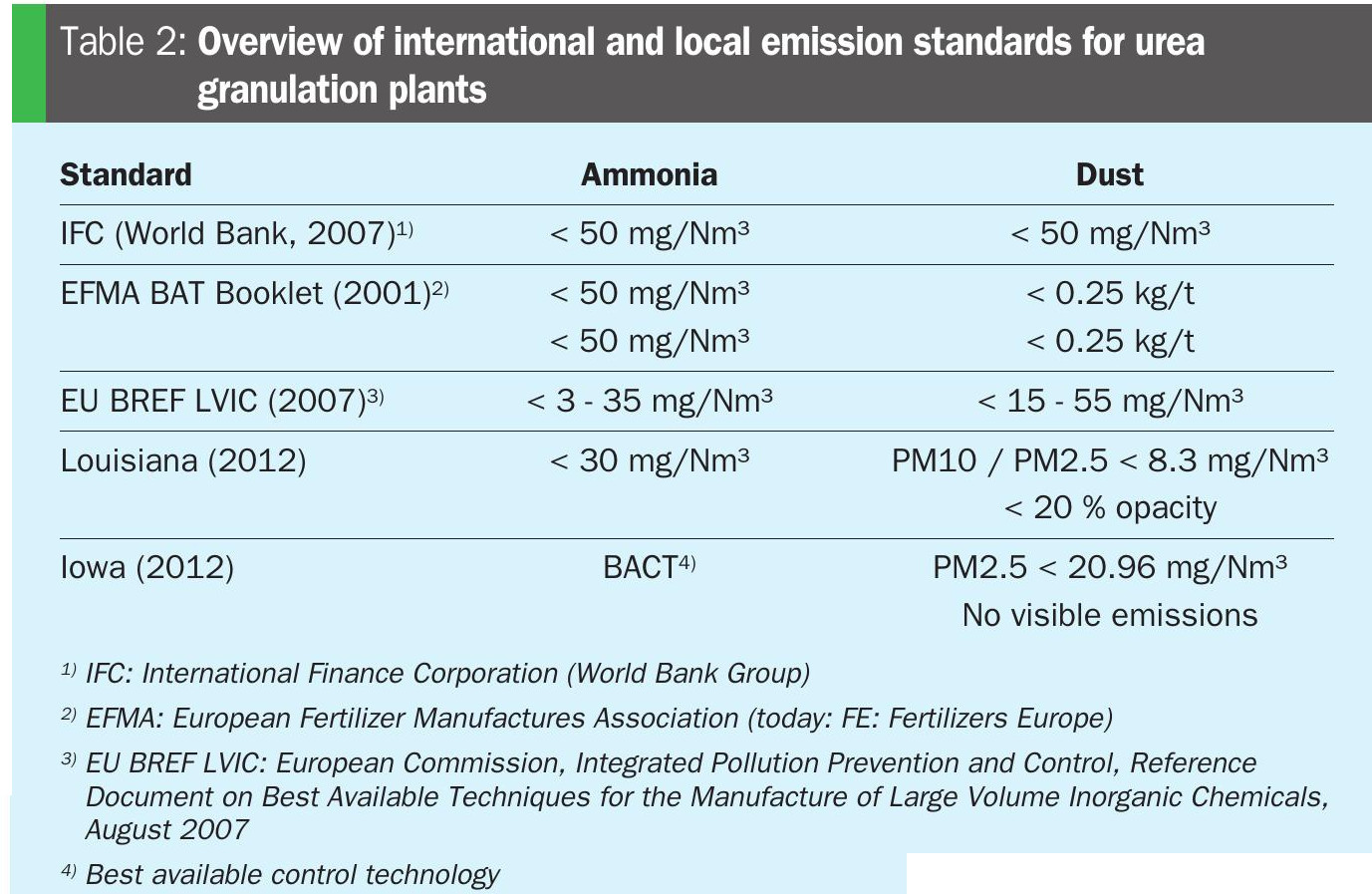
There are usually three emission points in a urea granulation plant:
• The low pressure (LP) absorber
• The atmospheric absorber
• The granulation stack.
Although the ammonia emission rate from the two absorbers in the urea melt plant (Figure 4) are low (approx. 4-6 kg/h), ammonia concentration limits can still be exceeded due to the very low total volume throughput. Ammonia emissions from the granulation stack (Figure 5), meanwhile, are an order of magnitude higher (approx. 80 to 90 kg/h), but the large volume of air dilutes ammonia concentration to around 100 mg/Nm3.


State-of-the-art scrubbers for ammonia and dust reduction (Figures 4 and 5) can now meet even the strictest emissions regulations. In operational plants, revamping for emissions reduction can be achieved by:
• Replacing the inner pads or trays of the existing scrubber
• Installing a dedicated acidic scrubber
• Replacing the existing scrubber with a new combined dust and ammonia scrubber.
Which option is selected depends on the current plant emissions achieved with the old scrubber system, the total new pressure drop, and whether changes are required to the air system. New scrubber pads, due to their lower pressure drop, can be installed without needing to replace the exhaust fan. Instead, in many cases the use of a small booster fan or a larger impeller is sufficient.
Scrubbing technologies installed in new plants built by Uhde in the US comply with local standards (Table 1). These scrubbers achieved ammonia emissions of 11.1 mg/ Nm³ (EPA 9 method) and dust emissions of 0.86 mg/Nm³ (EPA 5 method).
Acidic scrubbers are now established and well known due to their use in many new-build plants. Three types of acid – nitric acid, sulphuric acid and phosphoric acid – are all proven to be effective for ammonia reduction.
Soluble ammonium salts are formed when gaseous ammonia comes into contact with these three acids. These leave the scrubber as either ammonium nitrate, ammonium sulphate or ammonium phosphate solutions. Valuably, ammonium nitrate solution can be used in a urea ammonium nitrate (UAN) or ammonium nitrate plant.
If sulphuric acid is chosen, the resulting ammonium sulphate solution can be concentrated and sent to the granulator. When granulated together with fresh urea, the resulting granules have a small but significant sulphur content (0.1 wt-%) while their fertilizer-grade nitrogen content (> 46 wt-%) is maintained.
316/316L must be used as the granulator construction material if sulphuric acid is used due to its corrosive nature. This is not usually an option as most plants are built of 304. In these situations, a crystalliser unit can be used to produce an ammonium sulphate fertilizer from the resulting solution.
Finally, diammonium phosphate or monoammonium phosphate (DAP/MAP) can be produced from solution if phosphoric acid is used. Ultimately, the choice of acid is mainly influenced by three factors:
- Acid availability
- The ability to process the resulting ammonium salt solution
- The construction material of the granulation plant.
Improving plant availability
In addition to overhauling systems that have reached end of life, revamps can increase plant availability by replacing selected equipment with modern items based on new design concepts. One example is the replacement of the melt pump supplying the granulator with a self-regulating pump. The main feature of this pump is that it can be operated with almost zero suction head (NPSH = 0 m). This enables it to be installed just below the second stage evaporator in the melting plant.
The fact that the self-regulating pump does not require a NPSH leads to a couple of advantages. For example, because the pump can be installed above ground level, it can be directly connected to the granulators melt header. This also keeps the pipe length short as it avoids the need to route the pipe up and down. This configuration prevents build up on the pump’s suction side and minimises biuret formation.
A further advantage of self-regulating pumps with zero suction head is that no level control or pump protection is necessary. This avoids downstream plant shutdowns triggered by low suction levels. This can be a specific issue for those plants – with a granulation, and UAN and/or a DEF unit, for example – where the volume of solution sent to the evaporator varies.
Uhde holds the patent rights to apply this pump in a urea synthesis plant.
Input of the contractor – detail engineering
It is often assumed that the revamp is essentially fixed once the process concept is selected and the process design package (PDP) has been supplied by the licensor. However, an experienced engineering contractor can adapt the PDP by contributing valuable detailed engineering concepts – as shown in the following two examples.
The contractor is expected to come up with a suitable spare parts philosophy. A perfect example in urea plants is the philosophy for the high-pressure pumps. These are quite expensive and it is therefore important to work with the customer to find the best spare parts philosophy for their opex and capex needs.
The specifications for different pump capacities in the PDP do allow for various possible spare part concepts – enabling the contractor to develop the most suitable solution. For a typical arrangement of high-pressure pumps in a urea melt plant (Figure 7, left), the following three revamp philosophies are possible:
• Keeping existing pumps without modification. Both pumps must be kept in operation to achieve the required flow after the revamp. No spare pump is available. This option has the lowest capex costs but has high opex.
• Replacing the two existing pumps with new ones – each being capable of handling the increased flow after revamp. This provides redundancy as only one pump will be in operation at any time while the other remains on standby. This solution has the highest capex cost but the lowest opex cost.
• Installing a third pump alongside the existing pumps capable of handling the entire flow during operation (Figure 7, right) has distinct advantages. Operating either the new pump, or the two old pumps in parallel, is the lowest capex solution for achieving redundancy, as only one new pump needs to be ordered. This solution also has a low opex when the newly installed pump is in operation, with higher operating costs incurred when the two existing pumps are in operation. This solution does, however, require the availability of a sufficient installation area for the additional pump.

In a revamp with a so-called medium-pressure (MP) add-on, an additional section is added to the existing plant and operated at a pressure of approx. 20 bar. The unreacted carbamate removed in this section, because it is gaseous, is condensed in the MP carbamate condenser and then pumped and recycled back to high-pressure (HP) synthesis.
The heat of condensation is removed by cooling water. The cooling water is also temperature-controlled to 80°C to prevent the carbamate from crystallising.
As part of the revamp, the design of the closed cooling water loop can be improved by adding an additional circulation loop (Figure 8). Installing an additional pump generates a secondary circulation around the plate heat exchanger. This reduces the inlet temperature to the plate heat exchanger by mixing the hot return water with water from the outlet of the heat exchanger. This significantly reduced the tendency for fouling

In this specific example, the same modification was made to the cooling water loop of the high-pressure scrubber and the low-pressure carbamate condenser. Better performance and higher availability of the entire plant was achieved as a result
Summing up
There are different ways to conduct a urea plant revamp. Ideally, as a starting point, the licensor should provide reliable consumption data for raw materials and utilities in the initial phase of the revamp project. The contractor can then provide further detailed engineering input and evaluate the commercial feasibility of the revamp at an early stage.
Based on reliable emission figures for the urea plant, revamp contractors can check if any changes to existing environmental permits are required. They can also consider and provide engineering detail changes.
It is essential that all parties involved in revamps work together closely and exchange important information during all phases of the project to achieve the best possible outcome for the customer.