Sulphur 412 May-Jun 2024

31 May 2024
Fine-tuning SRU incinerator burners
SRU INCINERATOR OPTIMISATION
Fine-tuning SRU incinerator burners
The Aecometric 3rd generation burner was developed, installed and commissioned for an SRU incinerator with increased stringent demands to reduce NOx emission and lower energy consumption. Mason Lee of Aecometric Corporation reports on the new burner design and performance. The emission test results show a significant improvement in addressing these environmental concerns to achieve low NOx (<50 mg/m3 ) combustion and minimise CO (<200 mg/m3 ) emissions.
Incinerator burners play a crucial role in waste management and industrial processes, but it comes with environmental challenges related to emissions of nitrogen oxides (NOx) and carbon monoxide (CO). Aecometric’s 3rd generation incinerator burner represents a significant leap forward in addressing these environmental challenges by integrating advanced combustion techniques and emission control technologies to achieve low NOx combustion and minimising CO emissions.
Design principles and technologies
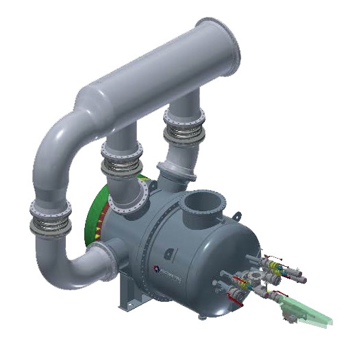
Careful control of combustion parameters and optimisation of burner operation by staging fuel and air is used to accomplish the even distribution of fuel and air while lowering the peak temperature profile within the combustion zone. Taking advantage of Aecometric traditional high intensity combustion technology, the design strategies employed in 3rd generation incinerator burners (Fig. 1) are aimed at optimising combustion efficiency while minimising pollutant emissions. Key design features of 3rd generation incinerator burner include:
- high intensity combustion with strong swirl within the combustor zone;
- advanced windbox configuration to incorporate features of staged combustion air and tail gas;
- secondary combustion air and tail gas introduced directly through the burner’s windbox;
- high degree of rotational velocity to tail gas stream toward intense combustion at the entrance of the chamber;
- comprehensive turbulence enhancement, optimised air-fuel mixing, increasing flame stability to promote efficient and clean combustion;
- combustion operating burners under fuel-lean conditions to minimise flame temperatures and inhibit NOx formation;
- precision tail gas distribution systems to ensure optimal fuel distribution and airflow pattern to stabilise combustion, minimise CO formation and enhance combustion efficiency;
- combustion control systems to implement advanced control systems that monitor effluent emission parameters in real-time and adjust burner operation for optimal NOx reduction.
Case studies and performance evaluations
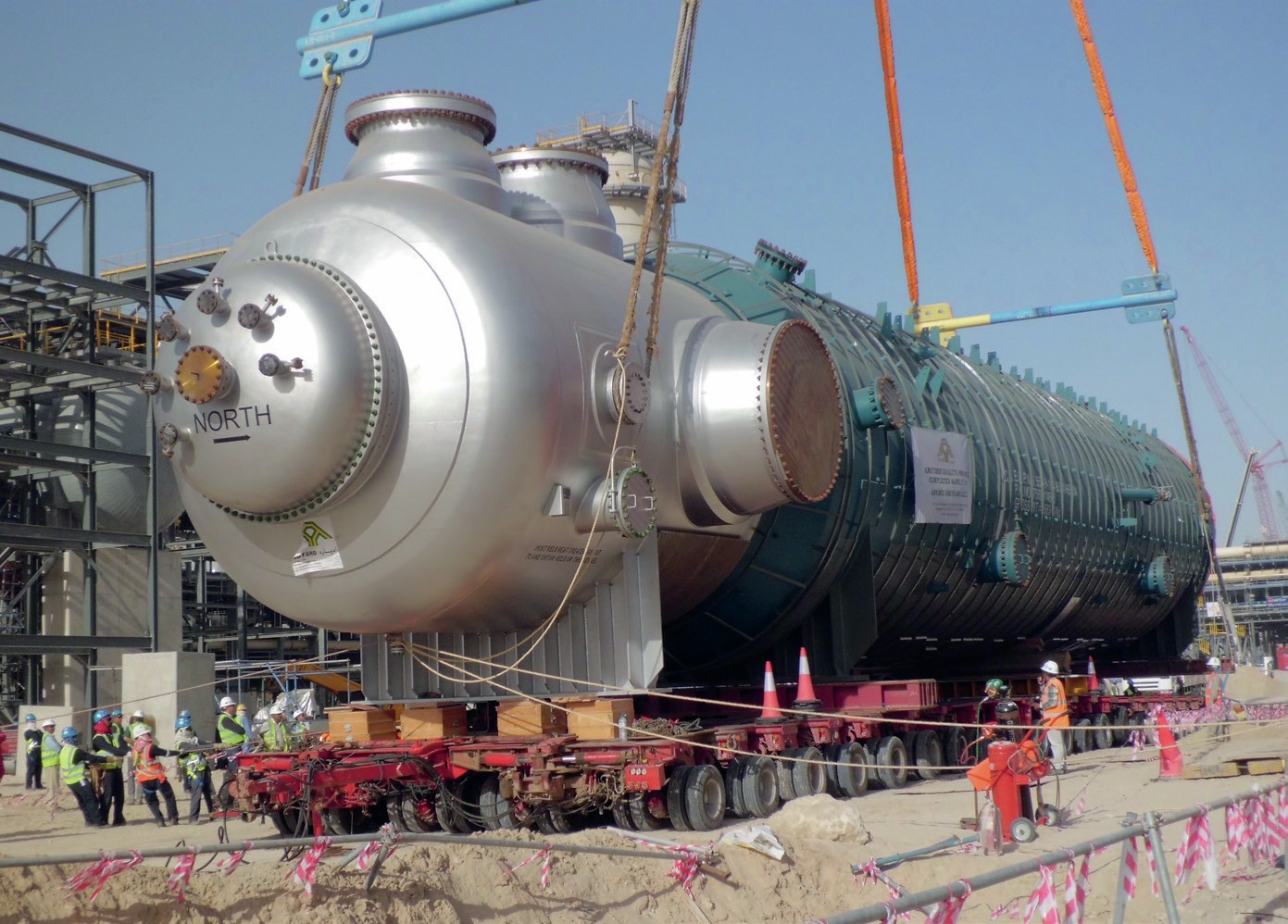
Based on the successful commissioning and operation of 2nd generation incinerator burners for Habshan 5 in 2013 (Fig. 2), extensive research has been conducted to develop and optimise combustion technologies aimed at further reducing NOx and CO emissions. This includes studies on combustion kinetics, pollutant formation mechanisms, and advanced combustion techniques such as lean combustion, staged combustion, and combustion simulation to support engineering design. These studies provide valuable insights into the practical implementation and performance improvement of the incinerator burners under real-world operating conditions.
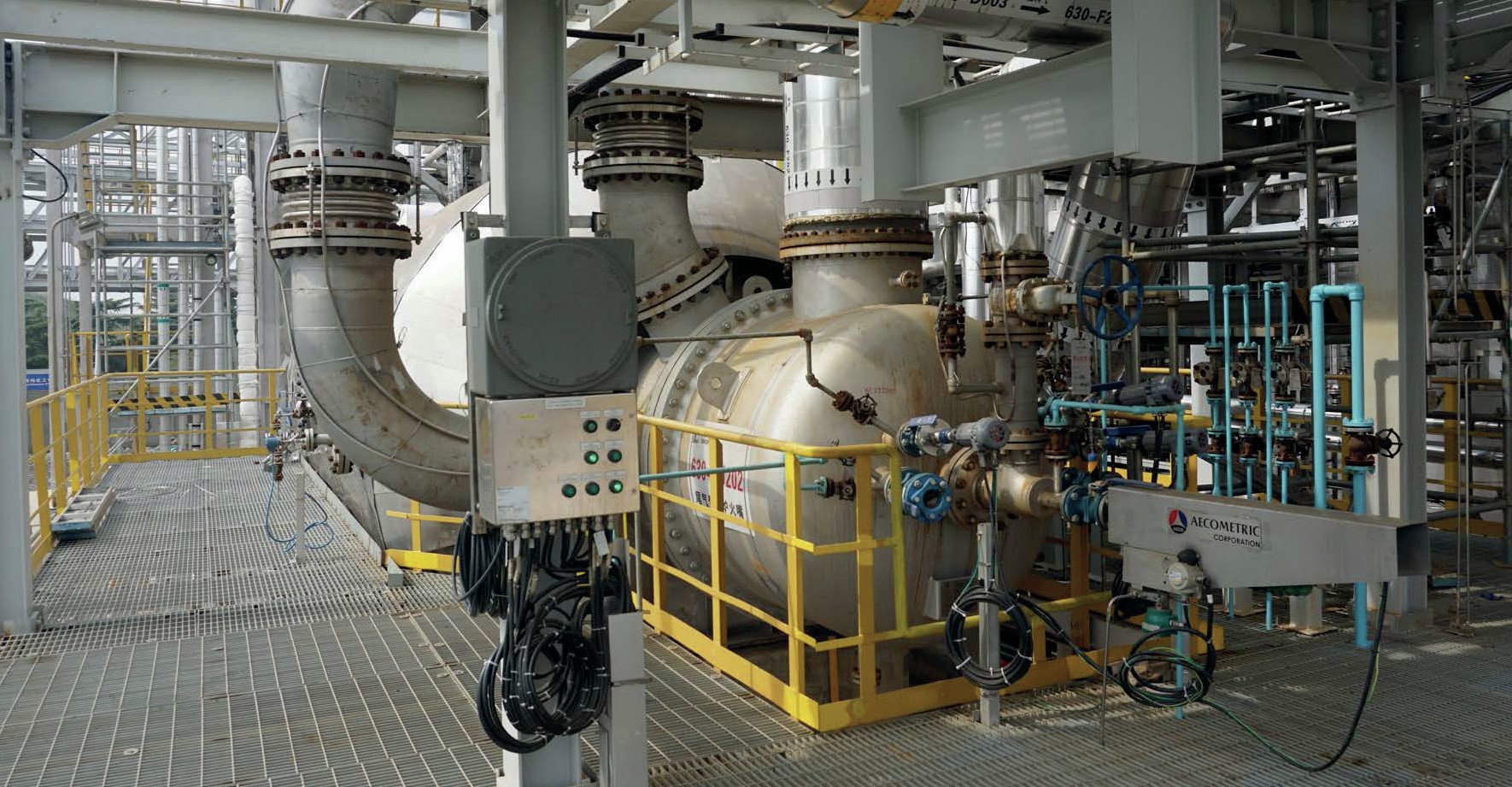
The 3rd generation incinerator burners were designed, installed, commissioned and operated at SINOPEC Yangzi Petrochemical in 2024 (Fig. 3). The main features of the 3rd generation incinerator burner configuration are:
- The tail gas is split into three streams, introduced through the burner windbox, and pre-mixed with secondary combustion air prior to entering the incinerator.
- A high swirl ratio of primary combustion air ensures high intensity combustion.
- Integration of staged combustion air and fuel is accomplished to optimise the combustion process and eliminate peak temperature profile in the combustion zone at an early stage.
- Even airflow and tail gas flow patterns are ensured to enhance the turbulent mixing effect during combustion.
- The mild temperature distribution is obtained to promote low NOx emission and minimise CO formation for complete combustion.
- The burner is able to meet stringent emission regulations while maintaining high thermal efficiency.
- The advanced 3rd incinerator burner for SRU applications highlights the improvements in combustion efficiency and emission control.
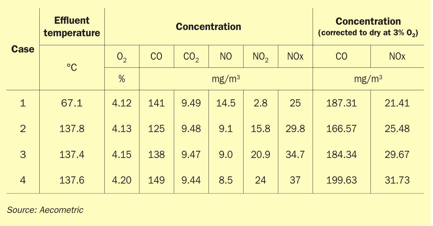
Preliminary emission tests to extract representative samples of the incinerator (BU202) exhaust gases was conducted in April 2024 using specialised sampling equipment SICA 230-4NLDL. This model of gas analyser comes with the function to measure the concentration of species including O2 /CO/NO/NO2 in real time. During the emission test, samples of the incinerator exhaust gases were collected at predetermined intervals over a specified period. The sampling location of the incinerator stack is located at a height of 70 m to ensure that the collected samples are representative of the emissions released into the atmosphere. To ensure the accuracy and reliability of the emission test results, QA/QC procedures including calibrating the gas analyser were implemented throughout the testing process. The typical emission results are shown in Table 1.
Environmental impacts and benefits
The development of the 3rd generation burner for SRU incinerators represents a milestone in an improvement of clean and efficient combustion technologies, offering solutions to the environmental challenges associated with tail gas incineration and industrial processes. Through the efforts to lower emissions of NOx and CO from incinerators and other combustion sources multiple environmental benefits are achieved, ranging from improved air quality and environmental sustainability to climate change mitigation and public health benefits. These benefits
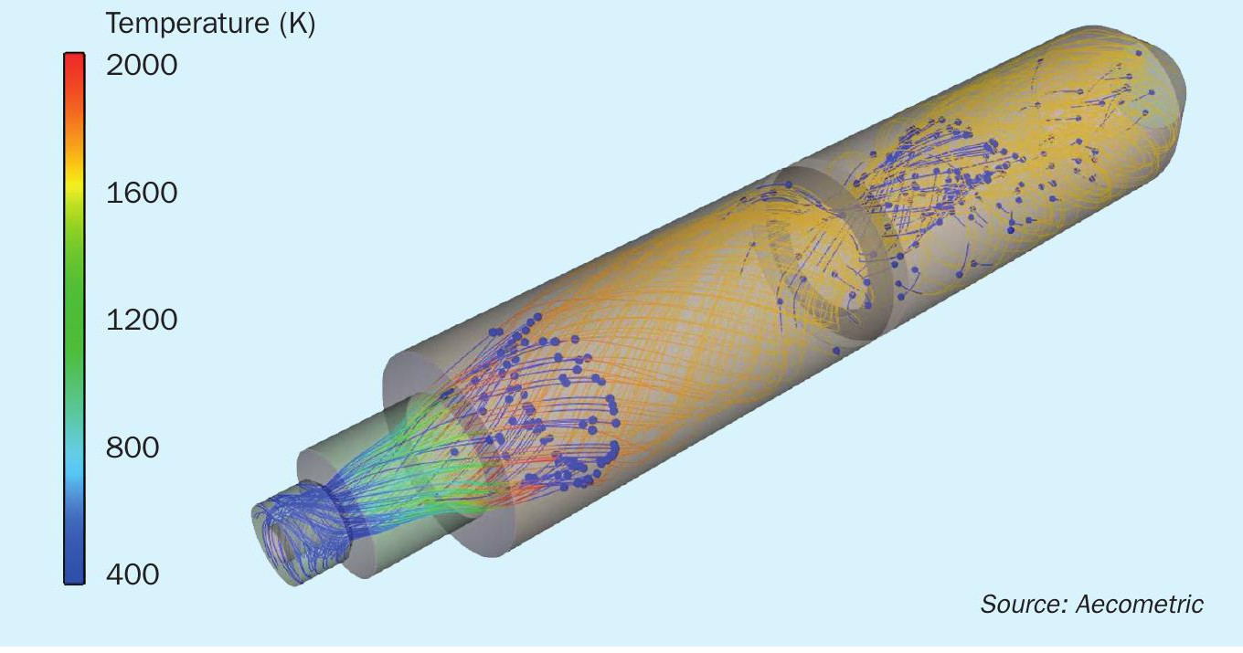
Future directions and challenges
While 3rd generation incinerator burners have made substantial progress in reducing NOx (<50 mg/m3 ) and CO (<200 mg/m3 ) emissions, ongoing experimental sample tests at different operation scenarios associated with fine-tuning of the incinerator and advanced research and development efforts are needed to address remaining challenges and further improve burner performance. The development of advanced control algorithms and predictive modelling techniques including computational fluid dynamics (CFD) modelling (Fig. 4) are essential. These techniques have been proved to be instrumental in optimising combustion systems for lower NOx emissions. Looking ahead in the future, these efforts, techniques and tools will allow engineers to analyse combustion processes in detail, identify areas of high NOx formation, and develop mitigation strategies.