Sulphur 390 Sept-Oct 2020

30 September 2020
Preventing explosions in molten sulphur tanks
SULPHUR SAFETY
Preventing explosions in molten sulphur tanks
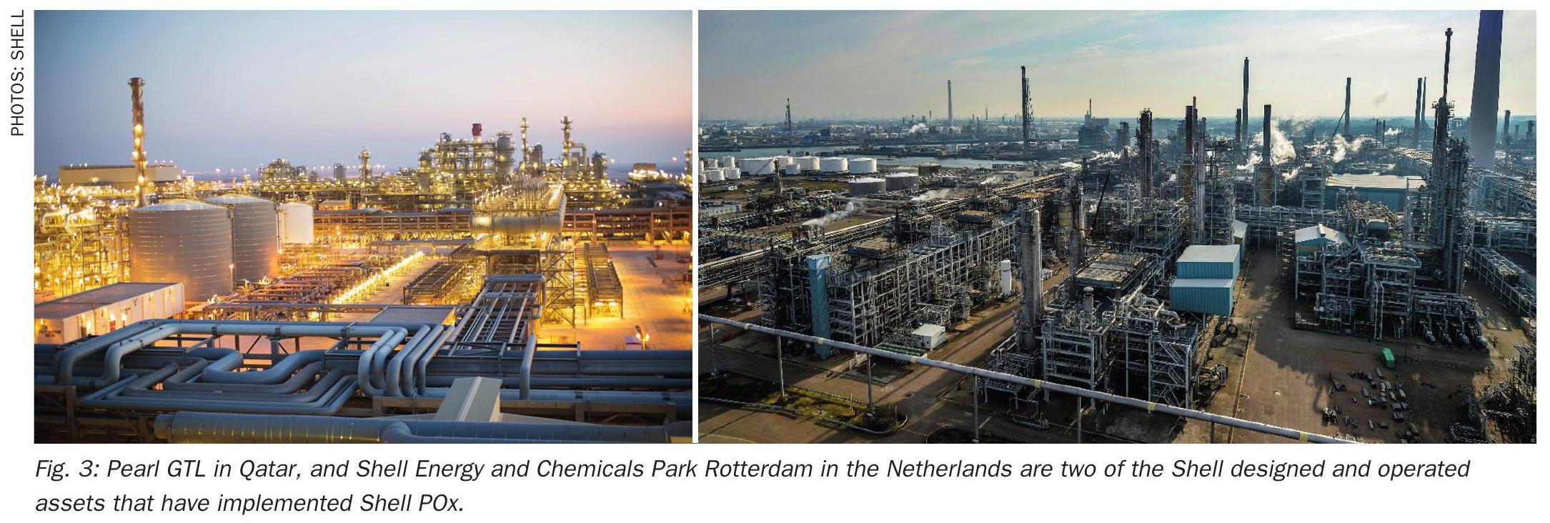
Undegassed molten sulphur can contain several hundred ppmw H2 S. If the headspace in the storage tank is stagnant, the H2 S can accumulate in the vapour space above undegassed liquid sulphur to dangerous levels. Sweeping and blanketing systems are commonly applied to manage the explosion risk in the headspace of molten sulphur storage tanks. D. J. Sachde, C. M. Beitler, K. E. McIntush, and K. S. Fisher of Trimeric Corporation review these approaches, outlining the benefits and limitations, design considerations, and industry experience/guidance for each approach. Calculation methods for natural draft flow of sweep air are also presented.
Molten sulphur is commonly stored in tanks in petroleum refineries, other oil and gas facilities, and at locations involved in sulphur processing, handling, storage, and loading. Hydrogen sulphide (H2 S) is a byproduct of processing natural gas and refining crude oils.
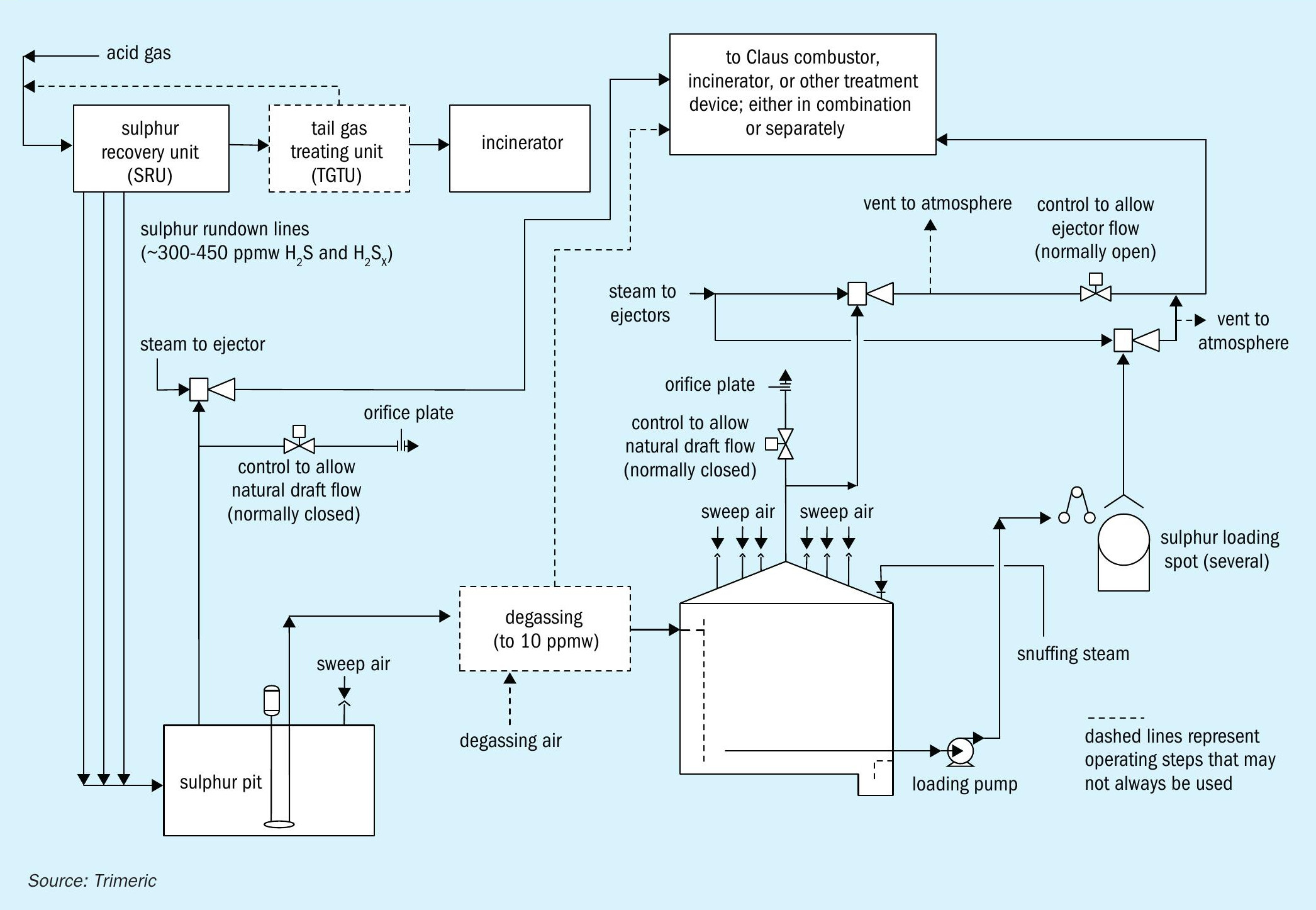
Environmental regulations often require that the H2 S be treated before emitting gases to the atmosphere. A modified Claus sulphur recovery unit (Claus SRU) is one common treatment method and involves converting the H2 S to elemental sulphur. The molten sulphur produced in a Claus SRU is stored and handled in a number of steps as depicted in the example in Fig. 1.
The molten sulphur produced in the Claus SRU contains soluble H2 S and hydrogen polysulphides (H2 SX ).During the storage of the sulphur, the H2 SX compounds decompose to elemental sulphur and H2 S as the sulphur cools and is agitated. This results in the formation of dissolved H2 S in the liquid sulphur that will desorb into the gas phase.The molten sulphur flowing into the pit from a Claus SRU is often assumed to contain 300 ppmw1,2,3 H2 S and H2 SX , although oxygen enrichment and subdewpoint operation can produce higher levels, e.g. 450 ppmw4 .
Sulphur degassing technology can reduce the H2 S in the sulphur to 10 ppmw or lower. Even if the molten sulphur is not purposefully degassed, some H2 S will evolve (50% has been reported2 ) from the pit depending on the operating conditions. The molten sulphur flows to a tank where it is stored until it can be loaded for transport. The H2 S concentrations in the tank headspace above undegassed sulphur could reach the tens of volume percent levels2 , posing an explosion and/or significant exposure hazard to personnel. (The OSHA permissible exposure limits5 for H2 S in the atmosphere are: 10 ppmv, 8-hr TWA, for construction and maritime industries). Even with degassed sulphur (e.g., to 10 ppmw H2 S), dangerous concentrations of H2 S can accumulate in stagnant tank vapour space (hundreds of ppmv to low volume percent levels)2 .
Because of the explosion hazard presented by H2 S, the molten sulphur tank design often includes a method to manage this risk. This article presents an overview of two broad approaches used to prevent molten sulphur tank explosions: sweeping and blanketing. Benefits and limitations of each approach are discussed, along with a review of the types of gases commonly used. Within tank sweeping methods, natural draft ventilation of tanks with air will be considered in detail. Natural draft ventilation utilises the temperature difference between the inside of the tank and ambient conditions outside of the tank to generate flow by natural convection and requires unique considerations for tank design and operation.
Preventing molten sulphur tank explosions
Safe handling of molten sulphur and the associated hydrogen sulphide is critical to prevent explosions in storage tanks. H2 S concentrations can reach or exceed the lower explosive limit (LEL), at which point an explosive gas mixture is present. Explosions appear to have happened with relative frequency, as can be assessed via Internet research and industry publications18 . To prevent an explosion, two general methods are to add gas to the tank vapour space either as a sweep gas or a blanket gas. Fig. 2 shows a simple schematic of the molten sulphur tank configurations with each method.
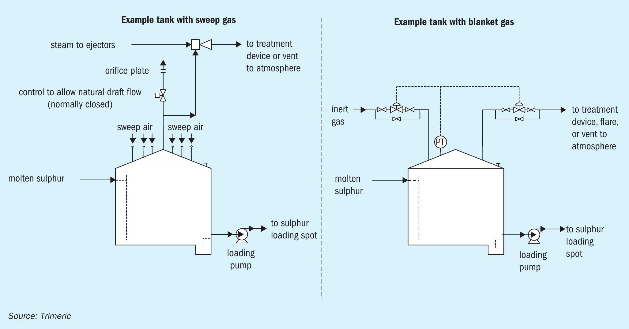
Sweep Gas
Sweep gas is often used to dilute the H2 S concentration in the vapour space to a safe margin below the LEL. Different sweep gases have been used including: air, nitrogen, fuel gas, steam, and others (e.g., CO2 ). Many molten sulphur storage tanks are swept with air. Ejectors, blowers, or natural draft effects pull air through inlets on the tank roof and out of a vent. The vent gas is emitted to the atmosphere or sent to another process downstream (H2 S removal, recycle to Claus reaction furnace, etc.). Sweeping produces a continuous flow of vent gas, and the tank operates under a slight vacuum. Air is a common sweep gas because:
- Air is readily available and inexpensive to use.
- The presence of oxygen keeps the atmosphere in the tank in an oxidising state, which helps prevent the formation of pyrophoric iron sulphides (FeS) on carbon steel surfaces. Iron sulphide forms in significant amounts under the reducing (without oxygen) conditions found in unvented tanks or tanks swept/blanketed with an inert gas (e.g., nitrogen). Under reducing conditions, iron sulphide is not a hazard and can even serve as a protective layer to prevent corrosion on carbon steel surfaces. However, once formed, iron sulphide poses a safety risk if it is subsequently exposed to air – for maintenance or cleaning – because the iron sulphide could spontaneously combust in the presence of oxygen, resulting in a sulphur fire or explosion.
- Flammability concerns with air (oxygen) can be mitigated by maintaining a safe margin below LEL and installing monitoring equipment.
- Sweep air can be handled by a number of downstream technologies that treat the H2 S in the vent gas.
Considerations for other sweep gases (e.g., nitrogen, fuel gas, steam) include:
- increased risk of pyrophoric iron sulphide formation;
- if the gas is not available on site, it may need to be produced or purchased, which may not be cost effective for the quantities required in “sweep” mode;
- fuel gas introduces additional combustible material into the tank vapour space;
- downstream treatment technology sensitivity to oxygen (e.g., poisoning of hydrogenation reactor catalyst with tail gas recycle) may favour sweep gases other than air (e.g., nitrogen)17 .
A few sites use steam to sweep molten sulphur tanks. As with inert gas-swept tanks, the tank usually operates at a small positive pressure. Using steam introduces water into the vessel, which with the exclusion of air (oxygen), can lead to the buildup of pyrophoric iron sulphide and potentially severe corrosion. However, if the walls of the tank are kept warm enough, it might be possible to prevent liquid water formation and perhaps reduce corrosion rates. The steam is sometimes vented to the atmosphere, but one variant of this approach condenses the steam exiting the tank. A venturi eductor with liquid water as the motive fluid can be used to condense steam/absorb volatiles including H2 S. The combined effluent from the eductor can be sent to a sour water system, waste water treatment plant, or other waste water system. This provides an alternative disposition route that is not available with the other sweep gases.
Blanket gas
Another method to prevent explosions in sulphur tanks is to blanket the tank with inert gas to limit the oxygen content in the vapour space by preventing air ingress. As shown in Fig. 2, the blanket gas (e.g., nitrogen) is fed to or removed from the tank to maintain a constant pressure as inbreathing or outbreathing occur (primarily via liquid movement). As such, the flow of N2 in “blanket” mode is intermittent and typically less than the gas requirement in “sweep” mode. The blanketing method may be used if a site does not have the means to handle and/or treat the large continuous sweep gas flow. However, inert gas blanketing can result in a significant amount of H2 S accumulating in the vapour space. This represents an explosion hazard if oxygen were to be subsequently unintentionally introduced to the tank. Inert gas blanketing also results in the formation of pyrophoric iron sulphide, and special procedures for maintenance would be required to prevent auto-ignition when tanks are opened to air. A source of the inert gas is also required. For these reasons, the use of inert gas blanketing to prevent molten sulphur tank explosions is less common.
An alternative to inert gas blanketing is to utilise an inert gas with some oxygen in it, such as post-combustion (e.g., exhaust or flue) gas. The gas would need to have sufficient oxygen to prevent pyrophoric iron sulphide formation but not enough oxygen to exceed the limiting oxygen concentration (LOC) for combustion of sulphur. The appropriate oxygen range would need to be determined with a safe margin applied. Instrumentation and gas-phase analytical measurements may be required to ensure proper oxygen levels. Exhaust gas, however, has been reported privately to Trimeric to have been successfully implemented in a molten sulphur tank. Blanketing with exhaust gas is also documented to have been practiced in the transportation industry for various cargos19,20 . Further, other cases have been identified where inert gas with some oxygen has been used for similar purposes in sulphur recovery units and other equipment where pyrophoric iron sulphide is a risk8,23 .
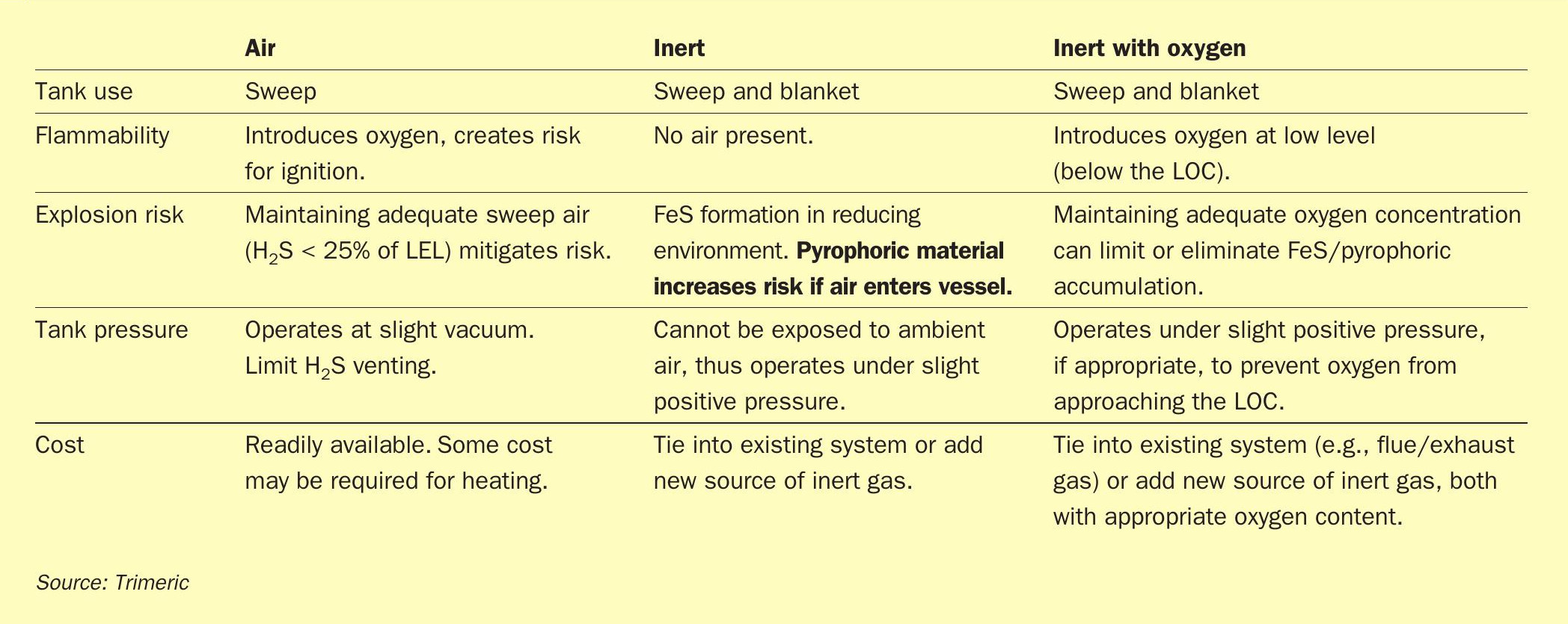
A summary table comparing the sweep and blanket gas options is presented in Table 1. The selection of sweeping or blanketing and the type of gas used is site specific. Many factors need to be considered including: i) the sulphur load and associated volume of gas needed; ii) whether the downstream H2 S treatment technology can handle sweep gas and H2 S levels, iii) the availability/cost of the gas; and iv) the site risk tolerance and degree of safety measurements in place to control issues with pyrophoric iron sulphide and hazardous tank vapour space environments.
Sweep gas and blanket gas are used to prevent explosions in molten sulphur tanks. Both approaches can be designed successfully, but sweeping with air appears to currently be considered best practice in some industries, such as petroleum refining. Given the common use of sweep air with molten sulphur tanks, the remainder of this article focuses on design considerations for sweep air systems. Additional details are available in the literature21 .
Designing for sweep air flow
Designing for sweep air flow requires estimation of the tank headspace composition to:
- define the sweep air requirement;
- determine impact/risks of vent gas properties on sweep air system design (e.g., plugging via sulphur vapour); and
- Identify risks to personnel or impacts on downstream treatment/disposition options.
The following discussion covers methods to estimate vent gas composition and sweep air flow and applies regardless of the sweep air motive method (natural draft or blower/ejector).
Typical sulphur species and estimation methods
The amount of H2 S that evolves from the molten sulphur into the tank vapour space can be estimated from i) measured H2 S and H2 SX concentration in the molten sulphur and ii) the liquid sulphur flow rate. There are different locations in the molten sulphur storage and handling process where these measurements can be taken. For example, the molten sulphur may be sampled for H2 S and H2 SX in the rundown lines to the pit, in the pit, in the tank, and/or at the loading stations. These measurements can be used to estimate the H2 S that evolves from the molten sulphur into the storage tank headspace. It may be possible to use only the pit molten sulphur H2 S measurement and assume some conservative percentage (e.g., 100% or other) evolves in the storage tank. An even more conservative approach is to assume all the H2 S present in the initial rundown (e.g., 300+ ppmw) sulphur evolves at each point in the process2 .
Different values for the molten sulphur flow rate can also be used. The nominal/ nameplate capacity of the SRU can be used, or the pump design rate or actual flow rate can be used, depending on the operating conditions of the specific facility and level of conservatism desired.
When making estimates of H2 S evolution, all layers of conservatism should be considered together to understand the impact on the design including:
- H2 SX compounds: Reported total H2 S in the liquid phase consists of both dissolved H2 S and H2 SX . H2 SX is relatively slow to convert to H2 S, so assuming that the total concentration of both compounds will evolve as H2 S is a conservative overestimation;
- Total H2 S evolution: It is unlikely that all of the H2 S entering the tank will evolve in the tank;
- Rate of H2 S evolution: The sulphur entering the tank does not degas instantaneously, in part because the sulphur in many tank designs enters through a down-pipe near the bottom of the tank and mixes with the rest of the sulphur in the tank, which limits the rate at which the sulphur can degas; and
- LEL values: The LEL for H2 S is often estimated at conservative temperatures that result in conservatively high amounts of sweep gas being used in the tank.
Since a variety of approaches have been reported in the literature for estimating H2 S evolution, the appropriate assumptions need to be rationalised for each storage tank design.
Various literature sources provide vapour-phase analytical data that can be used to estimate the SO2 , COS, and CS2 in the molten sulphur vapour vent streams3,6,7,10 . The literature data show significant variability, and their suitability for estimating the vent gas composition should be reviewed for the particular conditions of the tank design.
The amount of elemental sulphur vapour in the vent gas can be estimated by assuming the gas is saturated with elemental sulphur at the temperature of the molten sulphur and pressure of the vent stream. Vapour pressure information is available in the literature for elemental sulphur11 .
Finally, sulphur mist may be present in the vent gas. There is limited data available on the levels of expected sulphur mist in these systems10 . The amount of sulphur mist in the vent stream may vary significantly and is impacted by the air sweep rate, molten sulphur temperature, presence of any sources of agitation, steam coil leaks, etc. Care and experience is necessary to arrive at a reasonable value for sulphur mist.
Sweep gas flow requirement
Using 25% of the LEL is a common industry practice for calculating the sweep air flow rate and is recommended in various literature sources; values as low as 15%8 and as high as 35%9 as an upper limit to stop operation have also been reported.The LEL for H2 S is sometimes assumed for a conservatively high temperature, because a conservatively high temperature gives a conservatively lower LEL for H2 S and thus a higher sweep rate. A temperature of 330°F (166°C) is a conservative design choice when determining the required air rate and it is warmer than a tank would normally be operated, due to concerns with increasing sulphur viscosity at high temperature and increased fire risks. At this temperature, the LEL is 3 vol-%22 , so 25% of the LEL for H2 S is 0.75 vol-%. It should be noted that there is a chemical reaction in the elemental sulphur which consumes the H2 S and forms H2 SX that is favoured at higher temperatures (within a range), and this reaction would limit the mass transfer of H2 S into the gas12 ; however, higher temperature is more conservative for LEL and sweep air estimation.
The remainder of the article focuses on the natural draft ventilation design as this approach requires several unique design considerations not common to other motive methods.
Fundamentals of natural draft flow for tank ventilation
The air sweep rate needed to maintain no more than 25% of LEL for H2 S serves as the basis to design a tank for natural draft air flow. Natural draft flow utilises the inherent temperature difference between i) the vapours in the molten sulphur tank headspace and ii) the ambient conditions outside of the tank to create a natural air flow pattern to sweep the headspace of the tank. Since natural draft flow does not rely on a blower/ejector to move the air, it is considered the most reliable source of sweep air. However, the sweep air rate will vary with ambient conditions and operating conditions of the tank, so it is critical to design the tank to ensure that sufficient natural draft flow occurs at all relevant conditions the tank will experience. The following sections describe the fundamentals of natural draft air flow and the important design and operating parameters that impact the air sweep rate.
Theory of natural draft flow
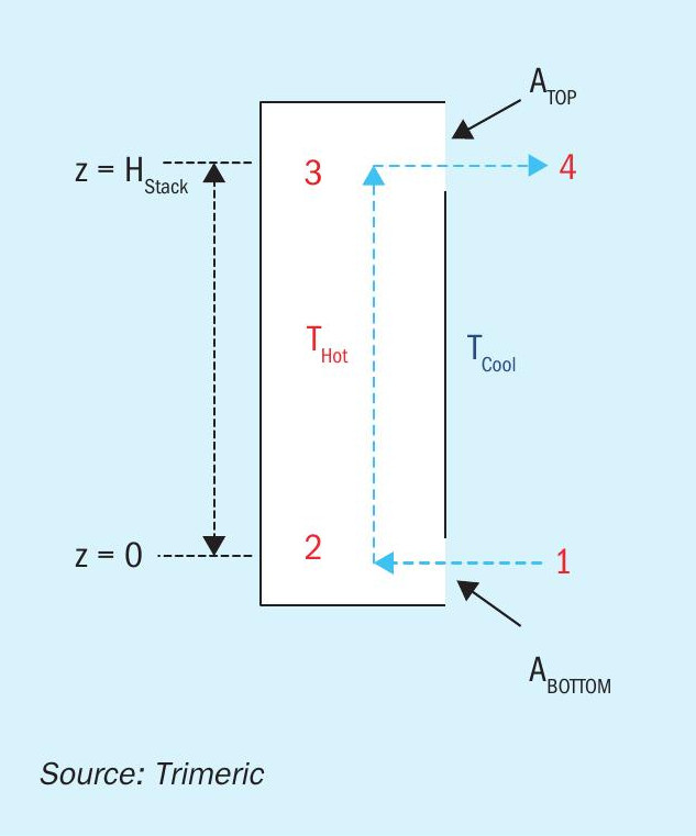
Natural draft air flow is sometimes described as the “stack effect” or “chimney effect” referring to the buoyancy-driven flow that occurs in a flue gas stack or chimney. The principles governing flow in these systems are the same as those in the natural draft flow in a tank and can serve as the basis to develop a simplified model and equations used to calculate draft flow in a tank. A “stack” model is depicted in Fig. 3.
Fig. 3 includes a proposed path for air flow – the air flow path is depicted as flowing from station 1 where ambient air enters the stack, warms up and rises in the stack, exits the stack to station 4. In addition, a mechanical energy or pressure balance (i.e., Bernoulli equation) can be written for the path from station 1 to station 4.
Point 1 and 2
The pressure difference across the air inlet at the bottom of the stack represents the frictional losses due to gas entry and should represent the specific inlet device (e.g., orifice, nozzle, etc.). Equation 1 represents the pressure difference across the entry (after simplification) and uses a discharge coefficient to account for frictional losses. Alternatively, fitting or loss coefficients could be used to evaluate frictional losses. The use of a single discharge coefficient for the inlet (and the outlet in the following equations) implies that the discharge coefficient is accounting for all frictional losses at these points (e.g., orifice at the inlet). If a unique design includes additional fittings or a unique design, the discharge coefficient may need to be modified accordingly.
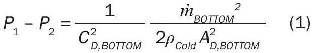
Where:
C D = Discharge Coefficient;
ṁ BOTTOM = Mass flow rate through the bottom stack opening;
ρ Cold = Mass density of “cold” or ambient air;
A BOTTOM = Cross-sectional area of bottom stack opening.
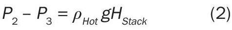
Point 2 and 3
The pressure difference between points 2 and 3 represents the weight of the column of hot air in the stack between the points (hydrostatic head). Equation 2 is a simple hydrostatic equation that is used to estimate the pressure difference based on the hydrostatic head between these points:
Where:
H Stack = Stack height = (Height of the top stack gas opening) − (Height of the bottom stack gas opening) (reference height).
g = Gravitational acceleration (in appropriate units).
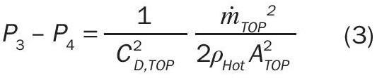
Point 3 and 4
The pressure difference from points 3 to 4 represents frictional losses at the exit of the stack and can be represented by Equation 3 (analogous to Equation 1 at the entry):
Where:
ṁ TOP = Mass flow rate through the top stack opening;
ρ Hot = Mass density of “hot” exiting air;
A TOP = Cross-sectional area of top stack opening.
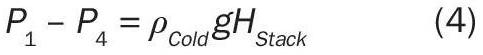
Point 4 and 1
The pressure difference between points 4 and 1 represents the weight of the column of cold air outside of the stack between the points. Equation 4 is a simple hydrostatic equation that is used to estimate the pressure difference based on the hydrostatic head between these points:
Deriving the mass flow rate of natural draft circulation
The driving force for the circulation of the air is the difference in the hydrostatic head inside of the stack versus outside of the stack (Equations 2 and 4). The weight of the column of hot air in the stack is less than that of the equivalent height of cold air outside of the stack due to the difference in density of the two columns of air. Therefore, a new expression can be written to quantify this driving force for flow by subtracting Equation 2 from Equation 4:

Equation 5 relates the pressure driving force for the flow to the density difference of the two columns of air. Equation 5 can be re-arranged to a more convenient form:

The left hand side of Equation 6 now represents the pressure difference across the openings where the gas flows into and out of the stack. Equations 1 and 3, respectively, can be substituted into this equation to relate the mass flow rate of the air to the hydrostatic pressure difference. After substitution and rearrangement (with ṁ BOTTOM = ṁ TOP for simplicity), the natural draft mass flow rate can be determined from Equation 7:
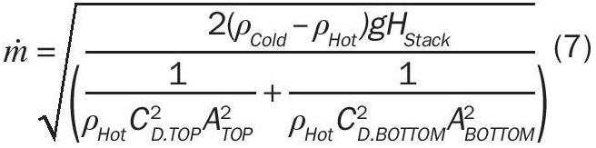
The mass flow rate of natural draft circulation is related to the height of the stack, density difference between the gas inside and outside of the column, and the size/ frictional losses of the opening of the stack (ignoring skin friction losses). This simplified model (and associated derivation) will serve as the basis for natural draft flow in a molten sulphur tank.
Stack model for molten sulphur tank vent
As the discussion of the stack effect illustrates, if a height difference is provided between the point of air ingress (cooler air) and the point of air egress (warmer air) for a molten sulphur tank, a density-based pressure difference (or buoyant force) will exist and will move air through the “stack”. In this case, the headspace of the tank and a central stack vent on the tank (described in the following sections) represent the “stack” for the air flow. Based on this description, a simplified model can be developed to represent the tank stack-effect flow, as represented by Fig. 4.
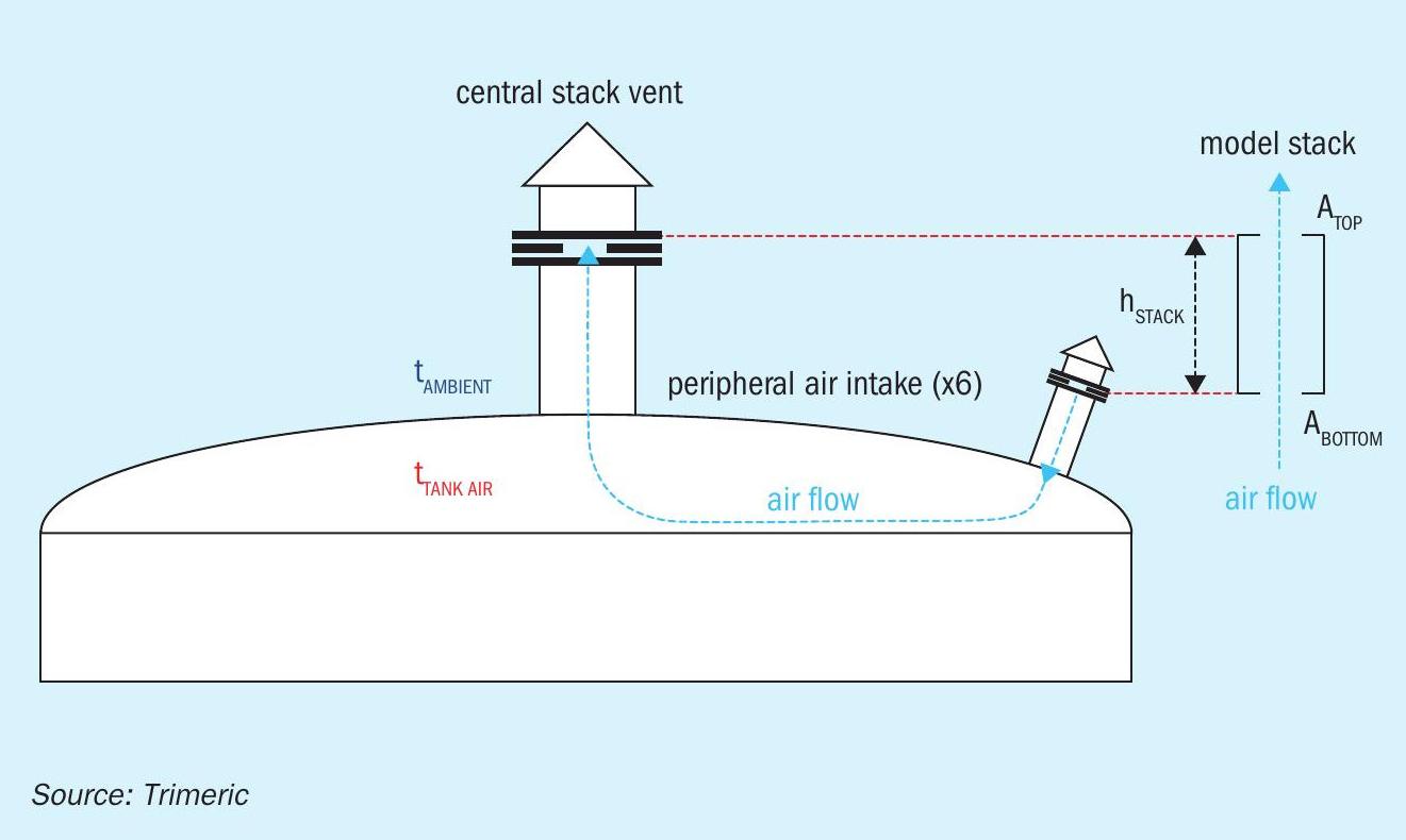
The total height of the stack includes the vertical distance from the inlets of the peripheral air intakes to the top of the central stack.
For design calculations, the air sweep flow rate required to maintain the tank headspace H2 S concentration below 25% of LEL (or other safe level) can be used to size the air intake and central stack vent via Equation 7. Some key assumptions and information for the calculation include:
- the temperature of the molten sulphur tank;
- the temperature distribution of the air in the headspace above the molten sulphur;
- pressure losses (frictional losses) into and out of the tank and losses to be considered along the flow path;
- the molecular weight of the air coming into the tank and the vapour leaving the tank;
- the atmospheric temperature and pressure for relevant design conditions.
The density of the ambient air and tank vapour are a function of the respective temperature and molecular weight of each gas, so accurate representation of the temperature and composition of the gas is critical to the design of a tank with natural draft circulation.
Equation 1 can be used to evaluate the pressure drop across the air inlets. This is an important aspect of the design of the molten sulphur tank as it should operate at a slight vacuum condition at the air inlet to prevent reverse flow through the air inlets13 . The vacuum requirement provides a further constraint to limit the variables that must be considered when designing the tank ventilation.
Sensitivity analyses and other considerations
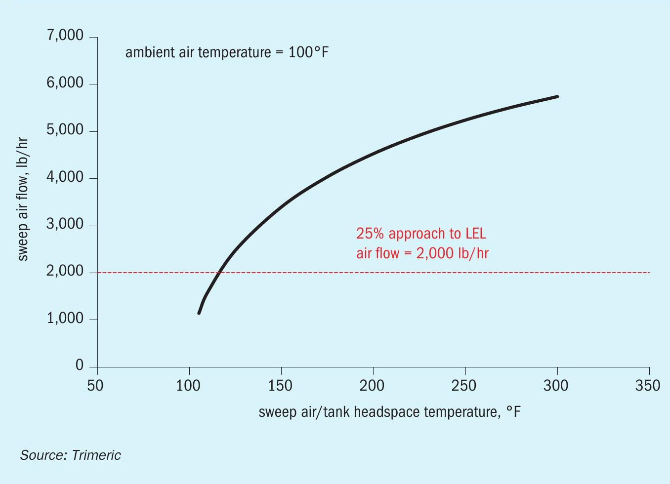
It is critical to understand the impact of the operating conditions and assumptions on the natural draft flow performance of the tank. Fig. 5 illustrates the impact of the tank headspace temperature on the sweep air flow rate.
The sweep air flow varies strongly with the tank headspace temperature. The tank headspace temperature, in turn, may be impacted by many other variables: the molten sulphur temperature in the tank, heat transfer rates to/from the vapour in the headspace, the turbulence/mixing in the tank headspace, conditions of the ambient air sweeping the headspace, etc. The problem may be further complicated by the fact that the air sweep rate itself may impact the tank headspace temperature, leading to a complex relationship between the temperature in the tank and the headspace temperature that provides the driving force for natural draft flow.
Also, the ambient conditions for a molten sulphur tank may vary widely across the seasons. As Equation 7 indicates, the density of the ambient air impacts the natural draft flow through the tank. The limiting condition for natural draft flow (lowest natural draft flow) is the highest ambient temperature experienced by the tank (e.g., maximum summertime temperature). This will produce the lowest driving force for natural draft flow (all other conditions fixed). The minimum ambient temperature condition leads to the largest natural draft flow rate that the tank will experience and is important for the design of the tank heating system (e.g., steam coils, external tank heating system, etc.). This condition sets the maximum heat loss for the tank and is the basis for sizing tank heating elements. Therefore, both scenarios must be evaluated during the design of the tank. Table 2 illustrates the 99.6% high and 0.4% low dry bulb temperatures for a generic site and the corresponding sweep air rates for a specific molten sulphur tank.
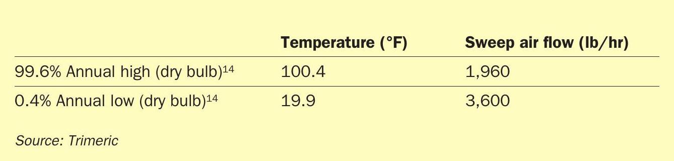
As Table 2 illustrates, the air sweep rate increases by more than 80% going from high to low ambient temperature. The natural draft system is designed to provide adequate air flow at summer conditions to meet LEL requirements and, as a result, the tank heating vendor is constrained by the large winter flow generated by the same vent system.
Other parameters and conditions may impact the natural draft design or operation. Examples include the following:
- composition of the vent gas (impacts molecular weight and density);
- wind effects (flow reversal through inlets);
- short-circuiting of air flow (flow leaves via an adjacent inlet);
- plugging risks for inlet and vent nozzles; and
- sizing of inlets and vents for tank overpressure/vacuum considerations9,15,16,21 (e.g., snuffing or sealing steam venting).
Systems with ejectors or blowers will have their own special considerations during the design process.
Summary
This article summarised approaches for preventing explosions in molten sulphur tanks through use of sweep gas or blanket gas. Air-based tank sweep systems that manage the H2 S concentration in the headspace (as opposed to excluding air/oxygen) are often favoured over inert-blanketed tanks from a safety standpoint, although both approaches can be successful with a careful design. The principles of natural draft air flow in molten sulphur storage tanks were reviewed. Natural draft flow through the tank is based on the temperature-induced density differences between the cold ambient air and the hot tank vapours, creating a natural circulation through the tank headspace. Design of the air intake and outlet stack vents can be achieved by a mechanical energy balance around this system. The natural draft design is sensitive to seasonal/daily variations in ambient conditions, vent gas composition, wind effects, tank-inbreathing and outbreathing, and other tank design choices and operating conditions which necessitate careful consideration for each tank design.
References