Sulphur 423 Mar-Apr 2026
20 March 2026
Sulphur plant tail gas incineration options
DECARBONISATION
Sulphur plant tail gas incineration options
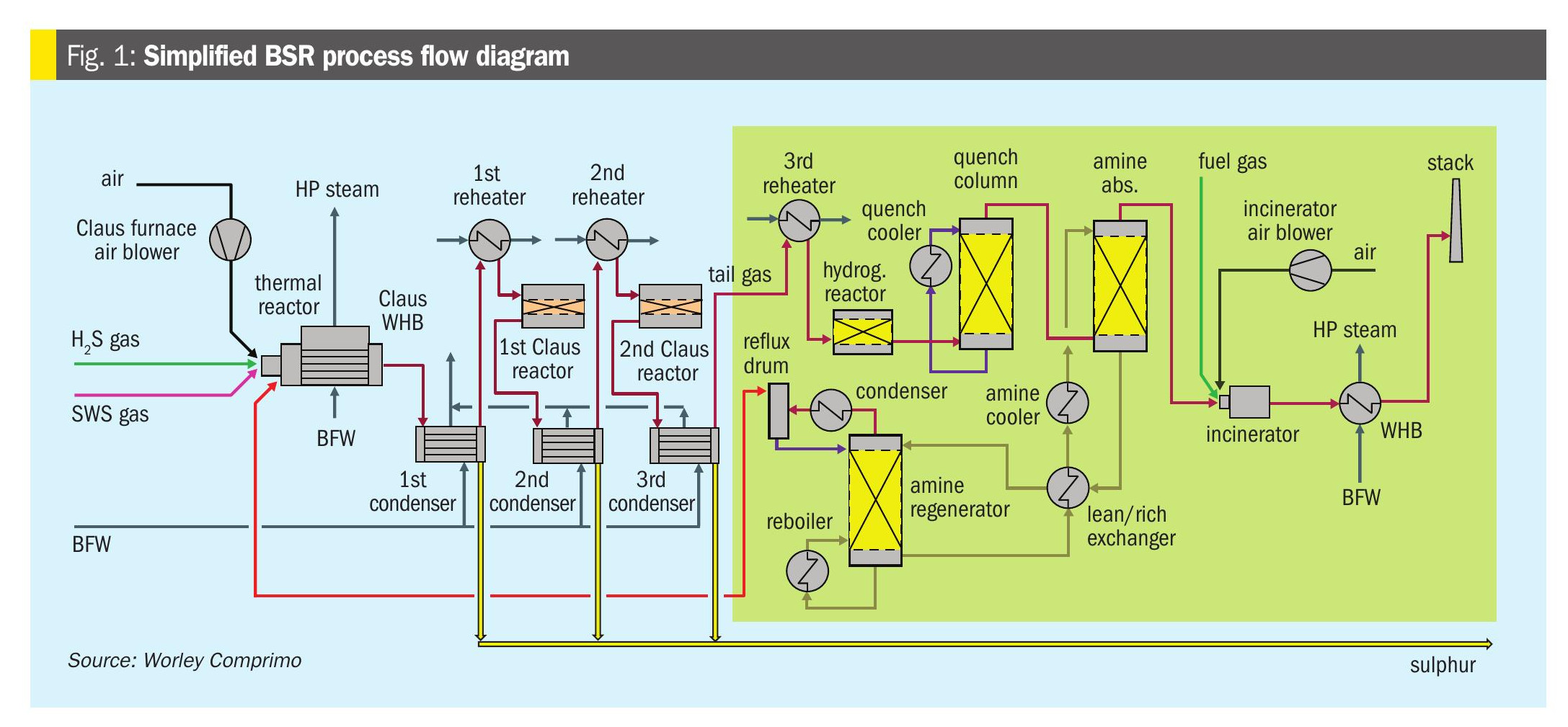
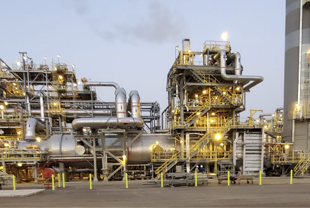
Sulphur recovery units in petroleum refineries and natural gas processing plants utilise incineration as a final treatment step for tail gas, ensuring that residual sulphur compounds are converted to less harmful emissions. Elmo Nasato of Nasato Consulting Ltd provides a comparison of the two sulphur plant incinerator options – thermal incineration and catalytic incineration – including key considerations for policymakers, businesses, and environmental advocates.
The treatment of sulphur-containing emissions is critical to environmental compliance and operational efficiency in sulphur recovery plants. Incineration is employed to oxidise hydrogen sulphide (H2S) and other sulphur species into sulphur dioxide (SO2), which can then be released under controlled conditions. The choice between thermal and catalytic incineration has significant implications for plant operations, emissions control, and overall cost-effectiveness.
This article compares two primary incineration techniques – thermal incineration and catalytic incineration – in terms of efficiency, environmental impact, operational costs, and practical applications. The sulphur recovery industry has primarily utilised thermal incineration due to the flexibility of operation. The choice between thermal and catalytic incineration has significant implications for plant operations, emissions control, and overall cost-effectiveness.
Sulphur tail gas incineration
The primary function of a sulphur tail gas oxidiser is to eliminate hydrogen sulphide, a highly toxic gas even at low concentrations. Typical emission limits for H2S from an oxidiser range between 5 and 10 ppmv. In many applications, carbon monoxide (CO) emissions are also regulated.
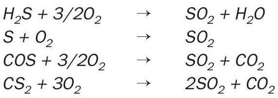
In a tail gas Incinerator, essentially all the sulphur compounds in the incinerator feed stream(s) are incinerated to SO2 by the high temperature oxidising atmosphere created inside the incinerator:
Heat is provided to the incinerator by combustion of fuel gas in the burner, and the fuel gas flow rate is adjusted to maintain the furnace temperature at a high enough temperature to ensure complete incineration of the sulphur compounds in the feed to the incinerator typically 1,200 to 1,400°F (650 to 760°C).
In recent years, much attention has also focused on other contaminants found in sulphur plant tail gas, such as carbon monoxide, nitrogen oxides, and hydrocarbons (particularly aromatic hydrocarbons). These contaminants often require higher incinerator temperatures to ensure adequate destruction (typically > 1,400°F (760°C)).
In a forced-draft incinerator, the incinerator temperature is also controlled by adjusting the fuel rate, but the combustion air is provided by combustion air blowers, which make it easier to maintain the proper amount of excess oxygen in the vent gas, thus ensuring complete destruction of all combustibles in the feed stream(s) to the incinerator and very importantly, minimising fuel gas consumption. Optimised operation reduces fuel gas consumption thus reducing operating costs and also minimises CO2 emissions.
It is also important to monitor the oxygen concentration in the incinerated vent gas. Too little oxygen (or no oxygen) may result in incomplete destruction of the sulphur compounds and hydrocarbons entering the incinerator.
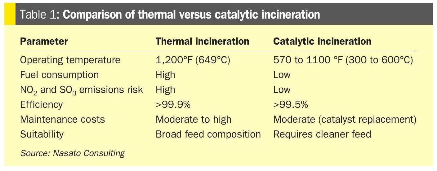
Hydrogen sulphide and organic sulphur compounds such as carbon disulphide (CS2) and carbonyl sulphide (COS) are an odorant pollutant of toxicity. The tail gas burning process utilises either thermal incineration or catalytic incineration. The thermal incineration method is carried out with excess oxygen at temperatures typically around 1,200 to 1,400°F (650 to 760°C). These elevated temperatures place thermal stress on the incinerator and stack. Catalytic incineration can oxidise hydrogen sulphide, sulphur vapour, carbon disulphide and carbonyl sulphide in the tail gas to sulphur dioxide at a lower temperature of 570 to 1,100°F (300 to 600°C). Although the output-to-investment ratio of thermal incineration is about 10% higher than that of catalytic incineration, catalytic incineration reduces energy consumption and operating costs by nearly 50%, enabling it to satisfy both environmental protection and energy-conservation objectives.
Thermal incineration
Process overview
Thermal incineration involves the high-temperature oxidation of sulphurous compounds, typically operating at temperatures above 1,200°F (650°C). The process ensures complete combustion of H2S and other hydrocarbons, converting them into SO2, CO2 and water vapour. Compared to CO, H2S is significantly easier to combust. The H2S autoignition temperature is 530°F (275°C), while CO requires a much higher temperature of 1,170°F (630°C) to ignite. For this reason, oxidiser manufacturers generally do not guarantee CO emission performance unless the unit operates at temperatures above 1,400°F (760°C). As with all combustion systems, increasing the operating temperature generally results in lower CO emissions – but it can also lead to higher nitrogen oxides (NO2) emissions.
Thermal incinerator.
It is important to distinguish between low-NOx burners used in fired heaters and the burners used in thermal oxidisers, as they are often mistakenly considered the same. Thermal incinerator burners can operate as either natural draft or forced draft systems, depending on the desired turndown ratio and the presence of downstream waste heat recovery equipment. Forced draft systems offer more precise air control and improved energy efficiency but come with higher capital costs.
Advantages of thermal incineration include:
• High destruction efficiency (>99.9%).
• Simple design and reliable operation.
• Handles a wide range of feed compositions.
Design options
- Natural Draft
- Lower capital cost
- Less efficient
- Forced Draft
- Higher capital cost
- More precise control (more efficient)
- Option to add waste heat recovery.
Disadvantages of thermal incineration include:
- High fuel consumption due to extreme operating temperatures.
- Risk of elevated NO2 and SO3 emissions.
- Higher thermal stress on incineration equipment and stack.
- Increased operational and maintenance costs.
Catalytic incineration
Process overview
Catalytic incineration uses a catalyst to promote oxidation at significantly lower temperatures, typically 570 to 1,110°F (300 to 600°C). This process converts H2S and other sulphur compounds to SO2 with improved energy efficiency.
Advantages of catalytic incineration include:
- Lower operating temperatures reduce fuel consumption.
- Lower NO2 emission and SO3 compared to thermal incineration.
- Extended equipment lifespan due to reduced thermal stress.
Disadvantages of catalytic incineration include:
- Catalyst deactivation over time, requiring periodic replacement.
- Susceptibility to poisoning by impurities in the tail gas.
- Higher initial capital costs for catalyst installation.
Comparative analysis
In sulphur recovery units (SRUs), the incinerator serves as a critical end-of-pipe unit designed to oxidise residual reduced sulphur compounds (e.g., H2S, sulphur vapour, COS, CS2) and unconverted hydrocarbons to meet environmental discharge limits converting all sulphur species to SO2 before release to the atmosphere.
Given the wide variety of sulphur plant configurations including the number of Claus stages, types of tail gas treatment units (TGTUs), and operating scenarios, the design and simulation of incinerators must be adaptable and precise. The list of considerations is provided below with an overall summary of comparison of a thermal versus catalytic incineration operation.
The incinerator ensures:
- Complete oxidation of residual H2S, sulphur vapour, COS and CS2 to SO2.
- Destruction of any unburned hydrocarbons or ammonia.
- Compliance with stack emission regulations (SO2, NO2, CO, etc.).
The performance of the incinerator is closely tied to what the feed stream is from upstream, which varies based on the number of Claus stages and the type and efficiency of the TGTU.
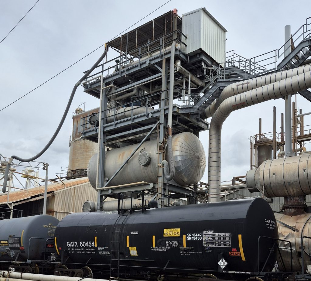 Catalytic incinerator.
In addition, the number of Claus stages directly affects the residual sulphur species content in the tail gas entering the incinerator:
- Fewer Claus stages:
- Lower sulphur recovery efficiency.
- Higher H2S and other sulphur species in the tail gas.
- Incinerator must handle a higher sulphur load.
- More Claus stages:
- Improved conversion of H2S to sulphur.
- Lower tail gas sulphur species, reducing incinerator duty.
A simulation is based on the number of Claus stages which affects both fuel gas requirement and oxygen demand in the incinerator to achieve full oxidation. The incinerator’s thermal rating and residence time must be adjusted accordingly.
The type of TGTU significantly alters the composition of gases entering the incinerator:
- No TGTU:
- Tail gas contains high levels of H2S, sulphur vapour, SO2, COS, CS2, and potentially hydrocarbons.
- Incinerator design must prioritise high destruction efficiency (>99.9%).
- Amine-based TGTU (e.g., SCOT-type reduction/amine):
- Converts sulphur species to H2S which is recycled to the feed of the SRU.
- Tail gas to incinerator is lean in sulphur, mostly containing inert gases and small H2S slip.
- Direct oxidation or sub dewpoint:
- Either converts H2S to sulphur directly in the tail gas unit or increases the Claus efficiency through sub dew-point operation.
- Overall sulphur recovery is typically in the range of 98.5 to 99.2%.
- Incinerator sees more H2S less fuel requirement for further oxidation.
- Incinerator oxygen demand, combustion air ratio, and stack gas composition are highly dependent on TGTU efficiency and type.
Incinerator oxygen demand, combustion air ratio, and stack gas composition are highly dependent on TGTU efficiency and type.
Sulphur plants operate under a wide range of scenarios, each requiring distinct simulation cases:
- Normal operation: Moderate tail gas sulphur levels, balanced fuel-to-air ratios.
- Start-up/shutdown: High variability in tail gas composition, requiring transient simulation.
- Turndown: Lower flow rates, reduced heat input, potential for flame instability.
- Emergency bypass (e.g., Claus or TGTU failure): Incinerator must treat high H2S streams temporarily.
Simulation and design tools must support:
- Dynamic behaviour (especially during transitions).
- Safety margin analysis for oxygen and temperature profiles.
- SO2 emission modelling under worst-case scenarios.
There are many proven sulphur plant simulation packages that provide steady state thermodynamic based calculations and the use of computational fluid dynamic (CFD) simulation tools that assist with reactor design. Some of the software packages and platforms include the following design packages and considerations:
- Aspen HYSYS, ProMax, ProTreat, or CFD tools for combustion modelling.
- Custom combustion reaction models for:
- H2S + O2 → SO2 + H2O
- COS, CS2 oxidation pathways
- CO and hydrocarbon oxidation
- NO2 formation under high-temperature conditions.
Key outputs:
- Stack gas composition: SO2, CO2, O2, H2O, NO2.
- Flame temperature.
- Combustion air/fuel gas demand.
- Destruction efficiency.
- Heat recovery potential (e.g., waste heat boiler downstream).
The environmental and operational constraints and regulations typically limit, but are jurisdictional specific:
- SO2 emissions (e.g., <250 ppmv).
- NO2 and CO formation.
- Visible plume control (SO3 or acid mist formation).
Incinerator simulations must also evaluate:
- Sulphuric acid dew point corrosion risk.
- Heat integration (e.g., with waste heat boilers).
- Stack dispersion modelling (for environmental permitting).
Effective simulation and calculation of sulphur plant incinerators depend on a comprehensive understanding of the entire sulphur recovery process, upstream Claus units, downstream TGTUs, and the specific operating scenarios involved. Tailoring incinerator design and operation to these variables ensures not only optimal sulphur destruction but also environmental compliance and operational flexibility. In summary the overall comparison of thermal versus catalytic incineration is shown in Table 1.
Environmental and regulatory considerations
Environmental regulations increasingly favour lower NO2 and greenhouse gas emissions, making catalytic incineration an attractive option for reducing the overall carbon footprint of sulphur recovery operations. However, the choice between the two methods often depends on the specific sulphur content in the feed gas, the availability of clean combustion air, and the economic feasibility of installing and maintaining catalytic systems.
Key design considerations
The end objective of thermal or catalytic incineration is to ensure destruction of trace sulphur species to meet regulatory requirements. However, each option has unique features that can be attributed to the unique features associated with burner design considerations versus catalytic reactor designs. The principles of reaction kinetics and reactor design are common to both thermal and catalytic incineration but there are key differences as described below.
Thermal incinerator design for sulphur plants
A key focus is safety, specifically the evaluation of NFPA 86 guidelines regarding purge requirements and how these guidelines can be applied to oxidiser restarts.
Designing a thermal incinerator for sulphur recovery requires a careful balance between efficient oxidation of sulphur compounds and preventing corrosion due to acid gas formation but also the additional thermal stress due to the elevated thermal incineration operation. As with any burner system the burner management system for ignition is critical but the logic tied into the SRU cause and effect is also a critical consideration. This involves precise control of temperature, oxygen levels, and gas mixing. Key design and operational considerations are outlined below:
Combustion and mixing
Excess air or superstoichiometric operation: Operate the thermal incinerator with excess air conditions to ensure complete oxidation of all trace sulphur compounds to comply with regulations and to satisfy the excess oxygen permit requirement.
Enhanced mixing: Use intensive mixing devices – such as choke rings, or checker walls – to ensure thorough blending of flue gas with incinerator waste stream tiein(s). This prevents gas stratification and promotes complete reactions.
Temperature management: Maintain consistent temperature distribution, particularly near the burner, to avoid hot spots that could damage internal components and to ensure complete combustion of sulphur compounds.
Material selection and corrosion prevention
High-temperature refractory: The high thermal stress of elevated thermal incinerator operation must be considered in the selection of refractory linings (brick or castable) that are resistant to high temperatures and corrosive sulphur species. Refractory materials must be evaluated for durability under the excess air operating conditions.
Dew point control: Ensure the steel shell remains above the acid gas dew point (typically 300 to 350°F or 150 to 175°C) to prevent sulphuric acid condensation and corrosion.
Flue gas management & emissions control
Vent stack design: Design of the stack for effective dispersion of flue gases. Stack height and placement must avoid interference with plant operations and comply with regulatory emission limits for SO2 and TRS.
Control systems and monitoring
Automated control systems: Implement control systems to maintain consistent operating conditions—regulating temperature, air-to-fuel ratio, excess air and mixing efficiency – to achieve safe, stable, and repeatable performance.
Emissions monitoring: Integrate real-time monitoring systems to track sulphur emissions (SO2 and TRS) and other operational parameters, ensuring environmental compliance and process efficiency.
A structured approach: This structured approach ensures that the thermal incinerator operates safely and efficiently while meeting emissions regulations and maximising sulphur recovery.
Catalytic incinerator design for sulphur plants
Designing a catalytic incinerator for sulphur recovery units requires detailed consideration of feed gas characteristics, thermal and reaction conditions, catalyst selection, and environmental discharge. The system must ensure complete conversion of total reduced sulphur (TRS) compounds to sulphur dioxide (SO2), maintain regulatory compliance, and operate safely with automated controls.
The primary function of the SRU catalytic incinerator is to promote the oxidation reactions associated with conversion of Claus tail gas sulphur species to SO2. Additional considerations include the oxidation of other SRU tail gas species such as CO and H2. Regardless of the catalyst selection, the catalytic incinerator reactor must employ the principles of chemical reactor design that stipulate maximum residence time distribution of all reactants, plug flow behaviour in temperature distribution, pressure distribution and flow distribution.
The most important design parameter used in sizing the catalyst beds is superficial gas space velocity, but it is critical to distribute the gas equally over the entire catalyst bed to maximise performance for all modes of SRU operation which include startup, shutdown, turndown, normal operation and, where applicable, tail gas unit bypass. Additionally, the reactor inlet deflectors must be designed to prevent gas impingement and/or flow patterns that can cause catalyst displacement. Catalyst is vulnerable to displacement but with proper gas distribution the displacement issue can be avoided. The space velocity is a measure of the volumetric flow rate of gas (at standard conditions) per volume of catalyst.
Designing a catalytic incinerator for sulphur recovery requires a careful balance between efficient oxidation of sulphur compounds and thermal excursions but with the benefit of lower thermal stress due to the lower catalytic incineration operation. This involves precise control of temperature, oxygen levels, and gas mixing. Key design and operational considerations are outlined below.
Feed gas and process conditions
Robust SRU front-end air control: During normal operation, the SRU receives amine acid gas and, where applicable, sour water stripper off-gas and converts H2S and other sulphur compounds into high purity sulphur. The combustion air flow to the Claus burner must be controlled accurately at all times for the proper extent of combustion of H2S. It is recommended to accomplish this through the feedforward ratio control in combination with the feedback air demand analyser signal control; the combination of feedforward/feedback defines the air control system. The design intent of the feedforward/feedback system is to optimise the control of the H2S to SO2 ratio to maximise sulphur recovery and to ensure adequate stability to respond to upset conditions that include change in feed rate and/or feed composition. The design intent of the decoupled feedforward/feedback system is to optimise the control of the H2S to SO2 ratio to maximise sulphur recovery, and to ensure adequate stability to respond to upset conditions that include change in feed rate and/or feed composition in order to protect the catalytic incinerator from thermal excursions.
Feed composition: The performance of the catalyst depends heavily on the concentration of TRS compounds such as hydrogen sulphide (H2S), carbonyl sulphide (COS), and carbon disulphide (CS2) as well as other contaminants like hydrocarbons, which can inhibit catalytic activity.
Operating temperature and residence time: Optimal catalyst performance requires maintaining specific temperature ranges. The incinerator must ensure sufficient residence time to achieve complete oxidation of TRS compounds.
Catalyst selection: Catalysts must be selected based on their ability to withstand contaminants in the feed gas while maintaining high oxidation efficiency. A robust, poison-resistant catalyst is essential for long-term performance. Additional considerations include the oxidation of other SRU tail gas species such as CO and H2.
Incineration efficiency and performance
TRS to SO2 conversion: The primary function of the catalytic incinerator is to oxidise H2S, sulphur vapor (where applicable), COS, CS2 and, where applicable, sulphur vapour into SO2. Efficient conversion minimises environmental impact and maximises compliance.
Performance optimisation: Efficient operation depends on maintaining target temperatures, ensuring proper catalyst function, and tightly controlling process parameters. Routine monitoring and catalyst maintenance are key to sustained performance.
Safety and control systems
Automated control system: A fully integrated control system is required to monitor catalytic incinerator feed combustion parameters such as temperature, air-to-fuel ratio, and flame stability. Real-time control helps ensure safe and reliable operation.
Fuel gas and air management: Automated systems should adjust fuel and combustion air to maintain optimal operating temperatures and safe burner performance.
Exhaust management and environmental compliance
Vent stack design: The exhaust stack must be properly designed to disperse SO2 emissions safely and prevent adverse effects on nearby structures, equipment, or personnel.
Regulatory compliance: The incinerator must meet all applicable environmental regulations, including limits on ground-level SO2 concentrations and total sulphur emissions.
Air emissions: The primary exhaust components are nitrogen and sulphur dioxide. Final emissions must be monitored and reported to ensure environmental compliance and permit adherence.
Conclusion
In a changing world, two major strategies have emerged to tackle rising greenhouse gas emissions: carbon reduction and carbon capture. While both aim to lower atmospheric CO2 levels, they differ significantly in approach, impact, and feasibility.
Both thermal and catalytic incineration play crucial roles in sulphur plant emissions management. Thermal incineration remains the preferred choice for high-load applications requiring robust processing capabilities, while catalytic incineration offers significant fuel savings and reduced CO2 and NO2 emissions for plants that can accommodate cleaner feed conditions. The selection between these technologies should be based on operational needs, cost considerations, and environmental compliance requirements.
Reference