Nitrogen+Syngas 398 Nov-Dec 2025
24 November 2025
Sustainable, efficient, and safe urea production
SUSTAINABLE FERTILIZERS
Sustainable, efficient, and safe urea production
MHI has successfully completed the Ghorasal Polash Urea Fertilizer Project in Bangladesh – the country’s largest fertilizer complex. Key features of the project include: the KM CDR Process™ that captures CO2, cuts emissions and boosts urea output; an energy-efficient granulation unit using a bulk flow cooler to reduce power demand; and reinforced digital safety management.
The fertilizer manufacturing industry is highly energy-intensive and heavily reliant on fossil fuels, making improvements in energy efficiency and emissions reduction particularly challenging. According to Menegat et al. in “Greenhouse Gas Emissions from Global Production and Use of Nitrogen Synthetic Fertilizers in Agriculture,” the production of synthetic nitrogen fertilizers accounts for 39% of total CO2 -equivalent emissions across the fertilizer supply chain.
As the pressure to reduce carbon emissions intensifies, several trends and innovations are emerging to lower the carbon intensity of fertilizer production. One of the key global strategies to reduce the carbon intensity of fertilizer manufacturing is by employing alternative ammonia synthesis methods with carbon capture, utilisation, and storage (CCUS). CCUS technologies are being integrated into ammonia production to capture and either store or repurpose CO2 emissions (e.g., as additional feed to urea plants), significantly reducing the industry’s carbon footprint.
Aside from carbon emissions, lean natural gas supply for ammonia plants and the use of power-intensive equipment in urea plants are other challenges in the fertilizer industry since both result in higher energy consumption. Methane-deficient feed gas not only raises production costs but also increases the plant’s carbon emissions. In the same manner, utilising equipment with high power requirements to meet quality granule product specifications adds not only to the operating cost but also to the emission impact. In an industry already struggling with energy efficiency and carbon emissions, this exacerbates both economic and environmental challenges.
In response to these challenges, Mitsubishi Heavy Industries (MHI) has been actively working to improve the energy efficiency and reduce the carbon emissions of fertilizer plants through various innovative technologies and solutions. As an example, MHI recently built the Ghorasal Polash Urea Fertilizer Project (GPUFP) with its own carbon capture technology and energy-saving equipment.
Aside from environmental impact reduction, automation and digitalisation of safety management in high-risk industries, such as construction and chemical plants has also become a global trend. MHI leveraged the power of digitalised technology to streamline the work permit approval process and access restriction to enhance the overall security and safety of the GPUFP project.
GPUFP project
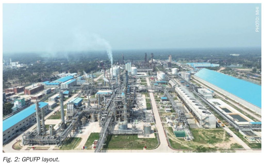
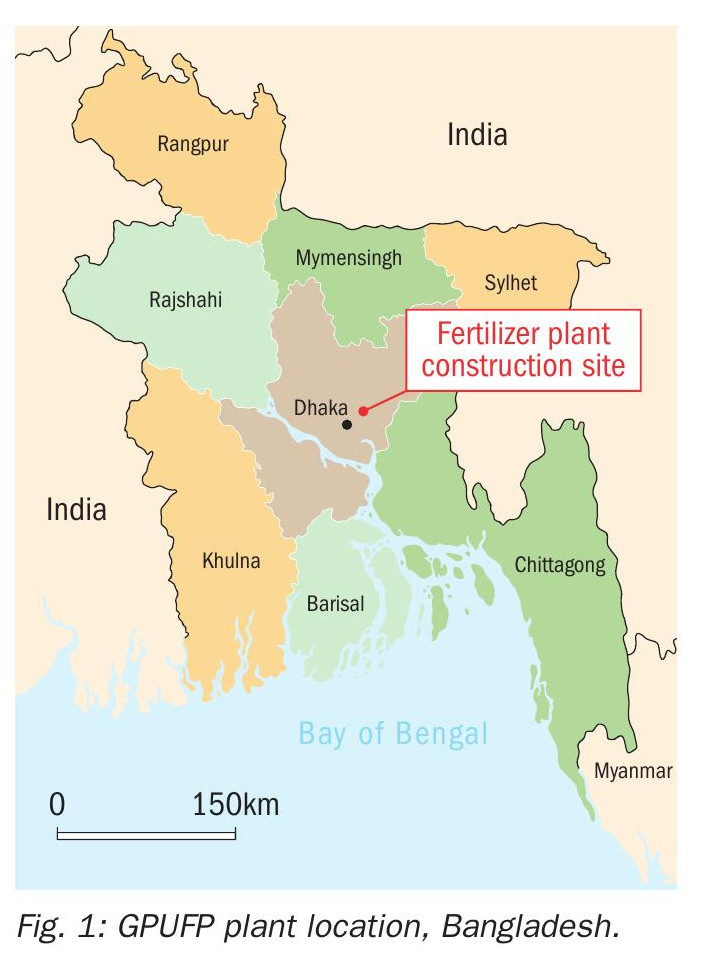
The Ghorasal Polash Urea Fertilizer Project (GPUFP) is the largest fertilizer plant in Bangladesh. It is situated in Polash, in the district of Narsingdi, 50 km northeast of the capital city of Dhaka (see Figs 1 and 2). The plant utilises domestically produced natural gas and has the capacity to generate 1,600 t/d of ammonia and 2,800 t/d of urea.
The project was developed for the Bangladesh Chemical Industries Corporation, a government-owned entity, with Mitsubishi Heavy Industries and China National Chemical Engineering No.7 Construction Co. as the contractors. It was executed under an EPC contracting framework.
The project’s process plant design for the ammonia plant was licensed by Topsoe, while the urea plant, comprising urea synthesis and urea granulation, was licensed by Saipem and thyssenkrupp Fertilizer Technology (tkFT) respectively.

The ammonia plant is integrated with a CO2 recovery plant that utilises the KM CDR Process™– MHI’s proprietary carbon capture technology, which reduces the environmental load and enhances urea production. The urea plant is equipped with a bulk flow cooler, designed for long-term operational energy savings. It has a self-sufficient utility and offsite plant designed by MHI, generating its own treated water from the Sitalakhya River, as well as steam, nitrogen, instrument air, and power.
The plant was built under strict safety management practices and was designed to ensure a high level of operational reliability, maximising inputs to enhance urea production while reducing the environmental load. The plant’s performance guarantee test run was completed in March 2024 and has been operated by the owner since then.
High-efficiency CO2 recovery technology
KM CDR process™
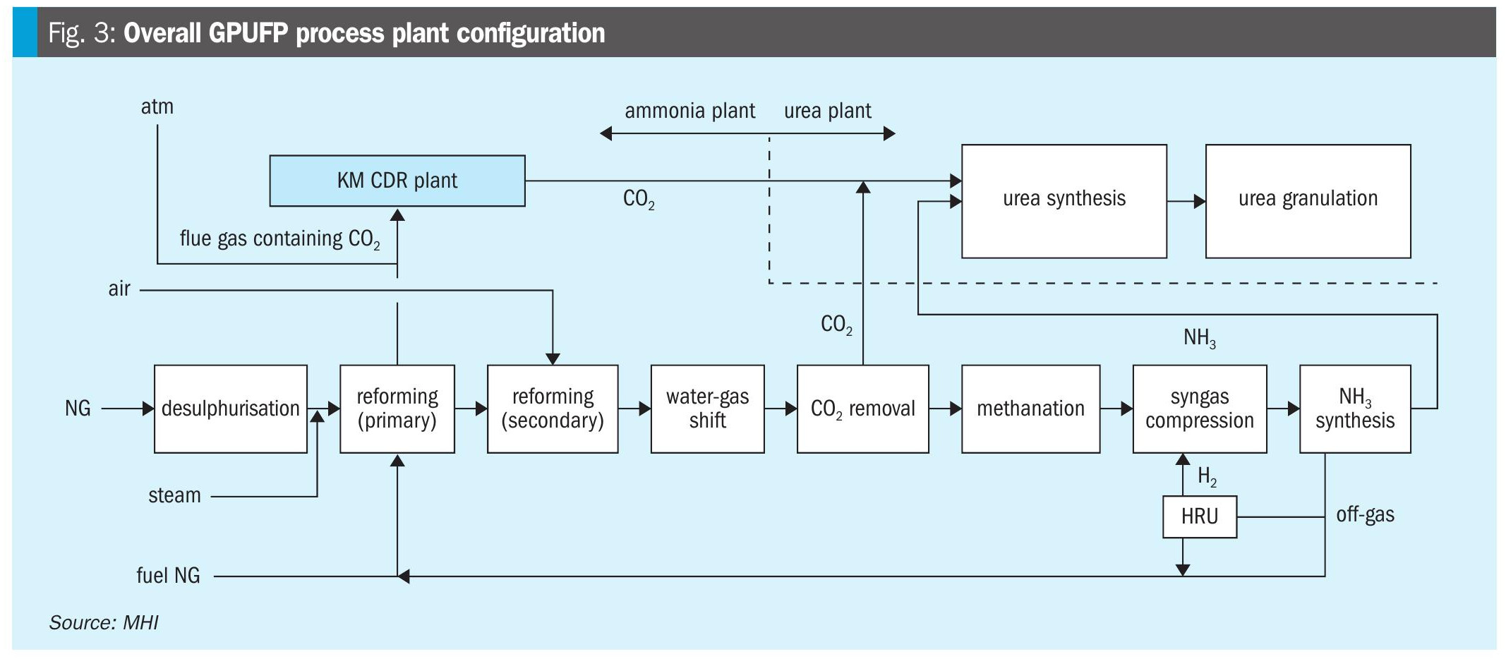
The ammonia plant in GPUFP utilises lean natural feed gas, which leads to lower CO2 production. To make up for the CO2 deficiency and meet the urea production requirements, MHI installed its own CO2 recovery technology known as the KM CDR Process™– Kansai Mitsubishi Carbon Dioxide Recovery Process™, one of the key features of the project. The feed material to the KM CDR plant is the flue gas from the primary reformer. The overall plant configuration, showing the KM CDR Plant, is illustrated in Fig. 3.
The KM CDR Process™ not only reduces the plant’s environmental impact in terms of CO2 emissions but also enhances urea production. It utilises MHI’s proprietary amine solvent, which has low volatility and is very stable against degradation. It is proven to effectively capture CO2 from the combustion gas of the primary reformer, up to 90%. The KM CDR Process™ consists of three main sections: the flue gas cooler, the absorber (for CO2 recovery), and the stripper (for solvent regeneration). Fig. 4 shows the process flow diagram of the KM CDR Process™.
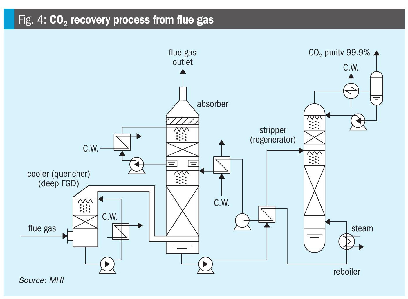
The flue gas cooler (quencher) cools the flue gas before it enters the CO2 absorber, enhancing the efficiency of the CO2 absorption reaction and reducing volatilisation losses of the KS-1™ solvent. The CO2 absorber consists of two main sections: the absorption section at the bottom, where conditioned flue gas flows upward through structured stainless-steel packing, and the washing section at the top.
In the absorption section, CO2 in the flue gas contacts the KS-1™ solvent, allowing for CO2 absorption. In the washing section, the treated flue gas is cooled to achieve good CO2 absorption before exiting the top of the absorber. The resulting CO2-rich solvent is then pumped to the CO2 stripper for low-pressure steam stripping. It is pre-heated using the heat from the hot lean solvent exiting at the bottom of the CO2 stripper. The CO2 is separated from the rich solvent at the top of the stripper and exits with 99.9% purity. It is mixed with the CO2 produced from the CO2 removal section of the ammonia plant before it is reacted with ammonia to synthesise urea.
Result of installing KM CDR Process™
The KM CDR Process™ in GPUFP has a CO2 production capacity of 240 t/d, resulting in a reduction of 25% of CO2 from the primary reformer. This corresponds to 326 t/d of urea production (or about 12% of the total granules produced per day). The CO2 captured by the KM CDR Process™ is converted to urea through a reaction with additional ammonia generated from recovered hydrogen. In GPUFP, about 108 t/d of ammonia is produced from recovered hydrogen from the purge gas stream of the ammonia synthesis section via the hydrogen recovery unit (HRU).
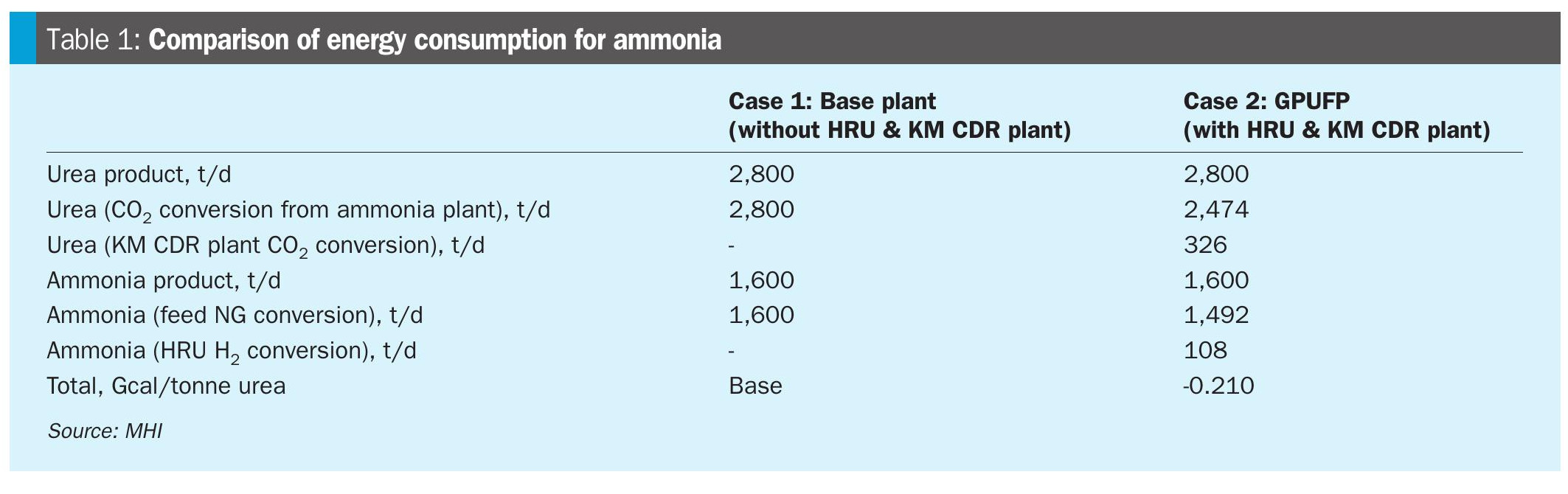
The energy consumption for ammonia production in the base plant, where neither the HRU nor the KM CDR Plant is installed (Case 1), is compared to GPUFP, which includes the HRU and KM CDR Plant (Case 2). In Case 1, if the HRU and CDR plant is not applied, the expected H2 quantity in the process natural gas is expected to be 7% higher than Case 2. This extra H2 requirement in Case 1 has an impact on fuel natural gas in the primary reformer and auxiliary boiler.
By installing the HRU, ammonia production is enhanced, and therefore, the required feed natural gas to the primary reformer is reduced. It correspondingly decreased the energy consumption in Case 2. Since off-gas from the purge gas absorber and off-gas absorber in Case 1 can be used as an alternative fuel to the primary reformer in Case 1, fuel natural gas consumption in Case 2 is higher. In Case 1, the steam requirement for the ammonia plant compressors is higher due to the 7% increase in the feed process natural gas H2 requirement. This makes the Case 2 boiler fuel NG consumption less compared to Case 1. Overall, the energy consumption is reduced by 0.210 Gcal/tonne urea (around 4%) with the installation of the HRU and CDR plant in GPUFP (see results in Table 1).
The installation of the CDR plant has minimal impact on the overall energy consumption of the ammonia plant. This is due to the reduced flow of LP steam to the process air compressor turbine (admission steam turbine type), as the steam is redirected to the reboiler for the KM CDR plant. Although the consumption of HP and MP steam increases, the overall energy efficiency still improves because of the reduced natural gas feed to the primary reformer.
In addition to the urea production advantage, the plant’s CO2 emissions from the reformer flue gas are reduced by 25% compared to the system without CO2 recovery. Reducing CO2 emissions in the primary reformer not only helps minimise direct emissions but also reduces the overall carbon footprint of the fertilizer plant. This is particularly important as industries are increasingly held accountable for their environmental impact, and companies with lower carbon footprints are more likely to meet sustainability targets and regulatory requirements.
By integrating CO2 capture technologies like KM CDR Process™, the fertilizer plant can be part of the global effort toward achieving carbon neutrality. The installation of the KM CDR plant also offers operation flexibility in terms of controlling the ammonia storage tank level. When the ammonia storage tank is filled with product ammonia due to an unexpected shutdown of the urea plant or maintenance, the tank level can be easily maintained or reduced by utilising recovered CO2 from flue gases without plant load adjustment. Through CO2 utilisation, the loss of synthesis gas in the ammonia plant is also prevented.
Energy saving equipment in granulation plant
Application of bulk flow cooler
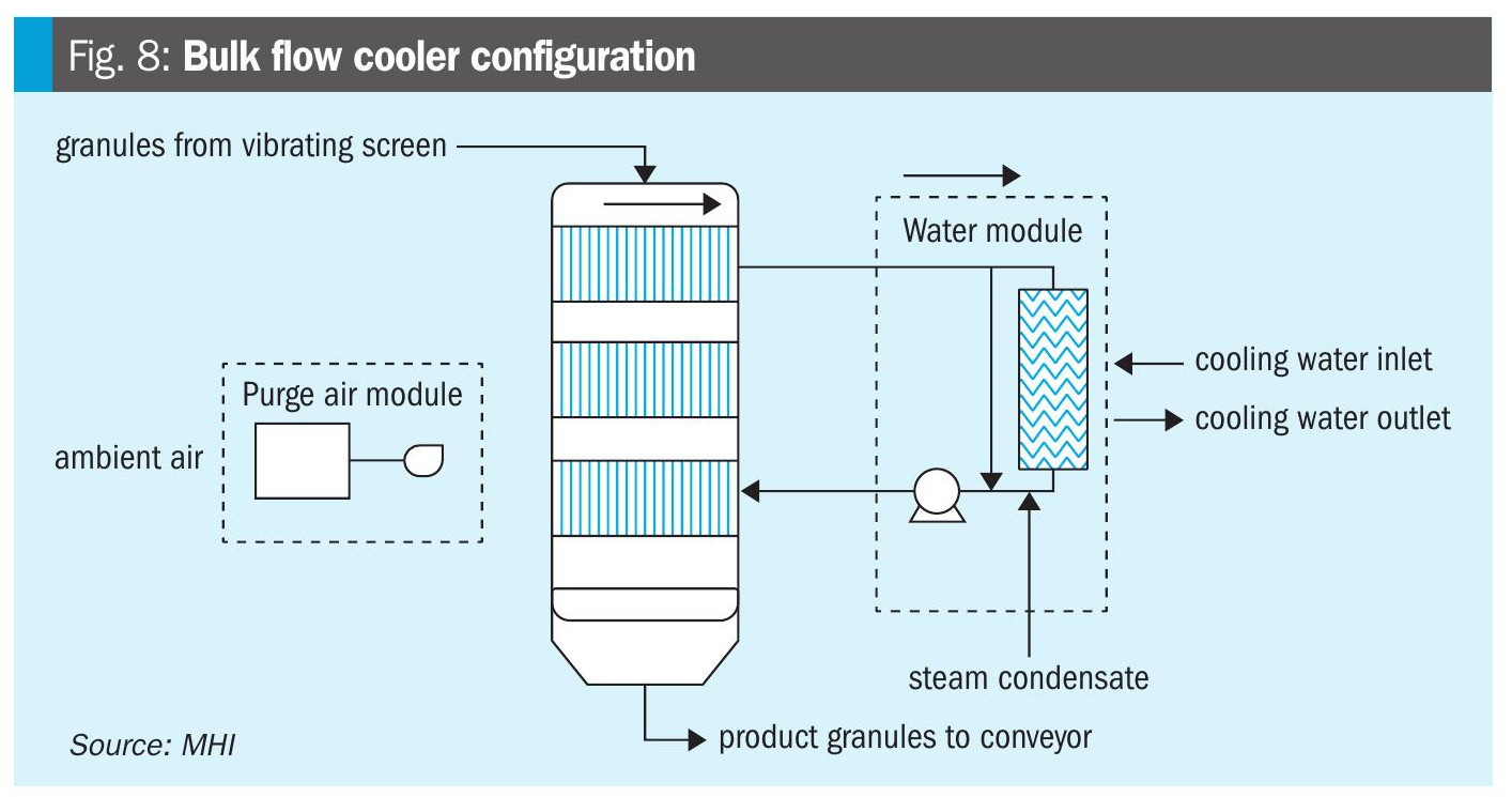
The bulk flow cooler is a simple piece of equipment designed for cooling granules using indirect heat transfer. It uses cooling water as the circulating medium in counter-flow with the granules for better thermal efficiency. The integration of the bulk flow cooler offers benefits such as low dust emissions and a compact installation design. More importantly, it also lowers the plant’s energy requirements by eliminating the need for a final cooler fluidisation fan and an ammonia chiller, which are found in conventional designs. The simplified block flow diagram of the conventional granulation plant is shown in Fig. 6, and the granulation plant with bulk flow cooler is shown in Fig. 7.
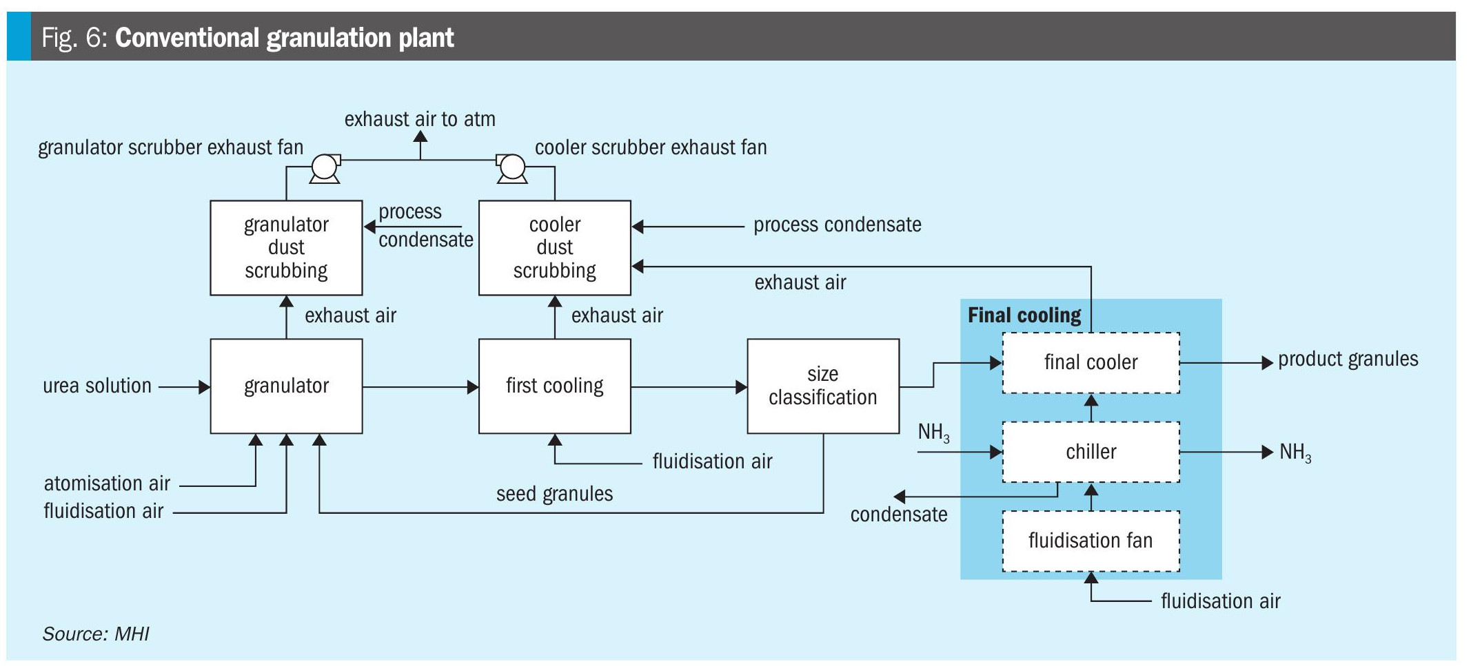
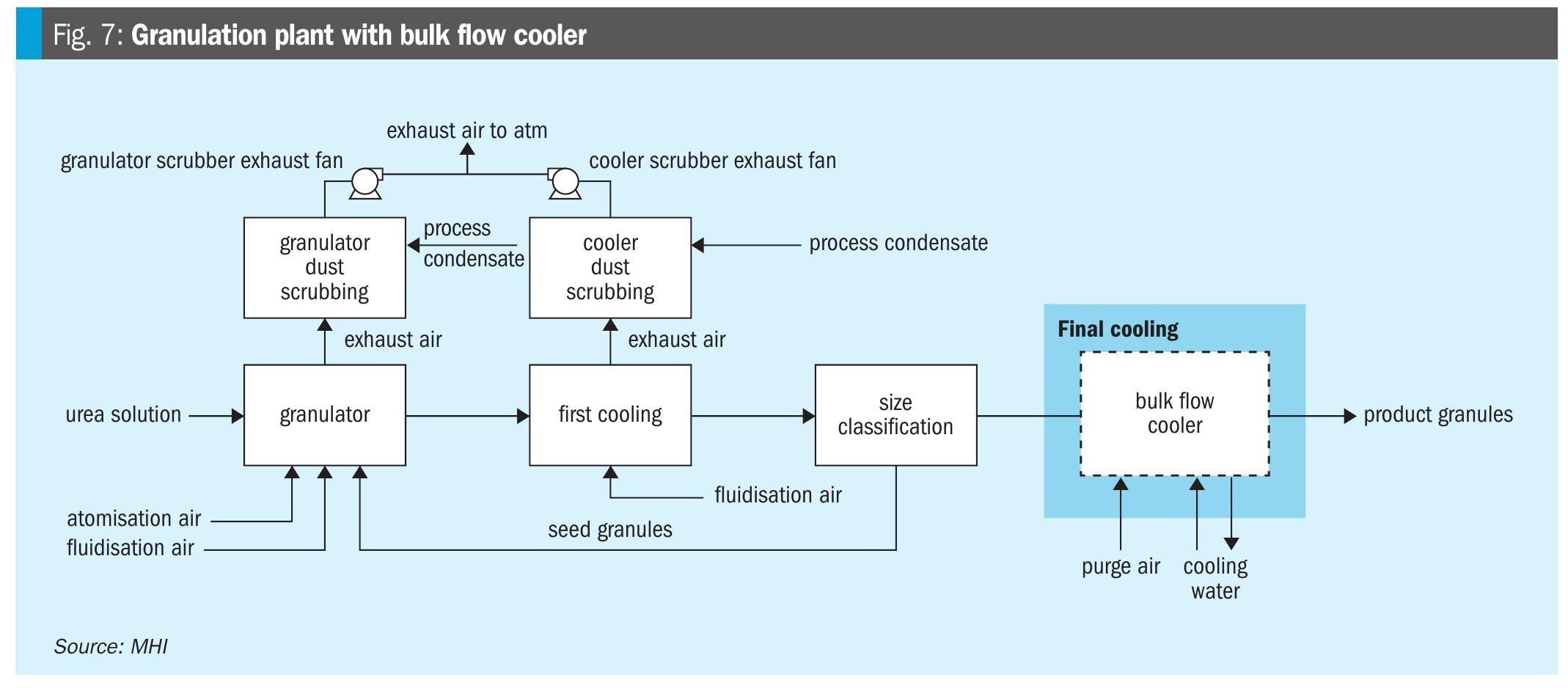
In the conventional design, cooling of granules to the desired product temperature requires fluidisation air to pass through the final cooler. Moisture is removed from the air by condensation using ammonia in the air chiller. However, in GPUFP, since the bulk flow cooler is utilised, cooling water flows countercurrently through parallel plates and is used as the cooling medium for the product granules. The granules pass through the bulk flow cooler in a slow and controlled manner, allowing sufficient heat exchange to achieve the target product temperature. The use of the bulk flow cooler produces low dust, which makes process condensate consumption in the cooler scrubber lower compared to the traditional design. In addition, since the fluidisation fan is not required, the load on the cooler scrubber is lower, making the cooler scrubber exhaust fan design smaller. The typical configuration of the bulk flow cooler is illustrated in Fig. 8.
The benefits of utilising the bulk flow cooler are summarised in Table 2. By replacing the final cooler with the bulk flow cooler in GPUFP, granulation plant power consumption can save 4.9 kWh/ tonne urea produced

Potential energy saving for future plant
After the GPUFP performance guarantee test run, two tests were conducted by tkFT to check the energy saving potential when operating parameters were adjusted. The tests conducted were:
- Granulator bed level reduction (Test 1)
- Atomisation air pressure/flow reduction (Test 2)
- During these tests, it was ensured that the quality of the products would not be compromised for the results to be considered satisfactory.
For Test 1, the product quality at the initial level of 50% was compared when the bed level was reduced to 30%. For Test 2, the atomisation air flow was decreased by reducing the atomisation air pressure to confirm the operating range of the spray nozzles. The tests were conducted for four days. The primary parameters changed during the tests are tabulated in Table 3.
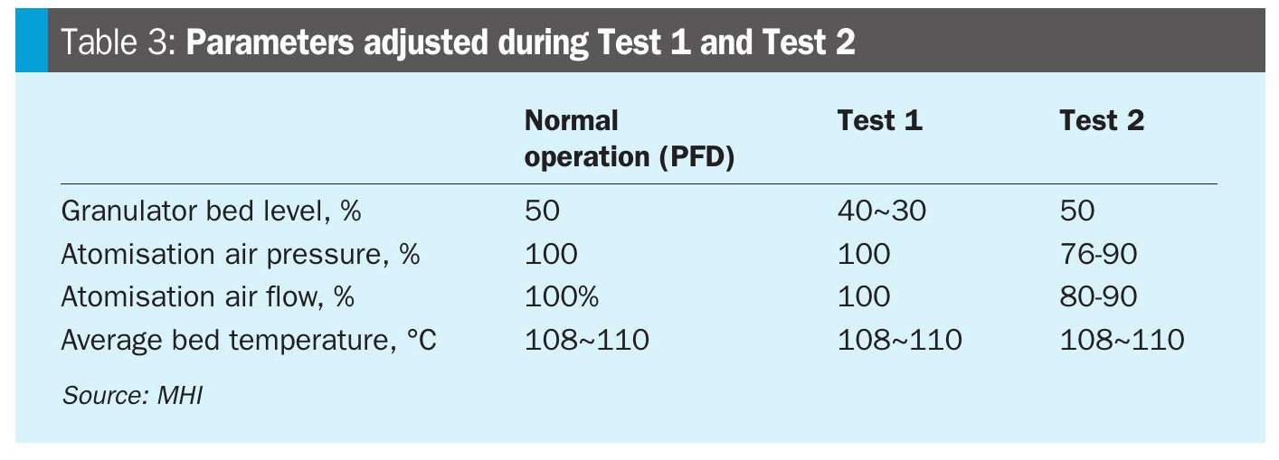
When the bed level in the urea granulator (Test 1) was reduced, the process and product quality remained consistent up to a 40% bed level. When the bed level was further reduced to 30%, there was a slight decline in product quality, particularly in terms of moisture content. There was no noticeable change in product size distribution or liquid recycle. The energy savings for Test 1 are estimated at -5.9% at a 40% bed level (without a change in product quality).
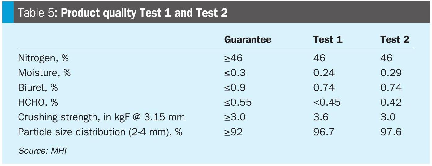
After reducing the atomisation air pressure (Test 2), no significant changes in product or process quality were observed, except for a few agglomerate formations on the granulator outlet screen. The reduction of atomisation air pressure to 76% impacted the power consumption of the atomisation air fan by -3.9%. Overall, it was verified that reducing the atomisation air pressure also has an energy advantage. The decision to lower the atomisation air fan pressure or flow should be based on granule quality, ensuring that the product guarantee values in GPUFP are maintained. Product quality is tabulated in Table 4.

Although the figures in Table 5 show valuable energy reductions, further energy savings in future granulation plants are possible. In the case of lowering the bed level, the material in the granulator becomes more evenly distributed and is more exposed to heat and fluidisation sources. A thinner bed requires lower fan pressure, which means less fluidisation energy is needed to keep the granules in motion. In addition, less heating of fluidisation air is required for cooling. Since there is less fluidisation, the scrubber exhaust fan capacity is also decreased. In GPUFP, this could be further realised if the fan type is changed.
Changing the type of fluidisation to provide a lower pressure increase, such as a variable speed drive (VSD), offers significant advantages not only in terms of energy savings but also in the improvement of process control. With a VSD, the fan can operate only at the required capacity, adjusting to the changing demands of the granulation process. In a lower granulator bed requiring a lower pressure increase, the VSD-type fan speed is more capable of adjusting the flow based on the actual process needs, rather than running at a constant full speed. This leads to substantial energy savings, as fans consume less power at lower speeds.
Digital safety for plant entry and work process
Electronic permit to work
The construction and commissioning of chemical plants requires a high level of coordination and planning, as many companies with their contractual obligations are involved, and the environment itself is considered high-risk. The permit-to-work system serves as a structured mechanism to ensure safety and compliance. It establishes clear protocols for authorising specific tasks and operations, facilitates communication among workers, supervisors, and safety personnel, and ensures that everyone is aware of potential risks, necessary precautions, and emergency procedures.
The transition to an electronic permit-to-work (E-PTW) system began during the COVID-19 period, driven by safety protocols, limited physical contact, and the global shift toward digitalisation and automation. These related issues were addressed in GPUFP and improved safety management control.
The main benefits of E-PTW are:
- easy access from any device with an internet connection;
- fully remote approval and closure process;
- permit status, attachments, and statistics available in real-time;
- instant search and retrieval of digital records.
Being able to check the status of the permit-to-work is one of the key points of plant entry control and is an integral part of safe plant operation: the working group will not be allowed to enter the process area without a PTW issued by the person in charge.
The lockout/tagout procedure (equipment and line isolation) is also established as a separate module of the electronic permit-to-work system, providing the same advantages of fast and remote approval processes and monitoring isolation status.
Access control with QR-code
Restricting access to the process area is crucial for safety, security, and regulatory compliance. Unauthorised access can lead to accidents, putting employees, first responders, and nearby communities at risk. Chemical plants are also vulnerable to sabotage, theft, and vandalism. Tightening access control measures helps protect key infrastructure and materials. Additionally, regulations require controlled access to ensure that only trained and authorised personnel handle equipment and hazardous materials.
The access control system to restricted areas in GPUFP includes the following:
- Special training for authorised personnel: Workers, supervisors, and above-level personnel receive training that includes information about main hazards, actions in case of emergency, communication channels, roles and responsibilities, and the procedure for entering restricted areas. After completing the training, the individual will be registered in the authorised personnel database and obtain an individual QR code.
- Physical access restrictions to the process area: The installation of fences and access gates with security guards. To enter the restricted area, individuals must have their QR code scanned by security guards for verification, along with an issued permit to work, mandatory personal protective equipment (such as a full-face gas mask with an ammonia filter), and personnel from the worker category must be accompanied by supervisors or above-level personnel.
- Restricted area entry monitoring: Scanning the individual QR code by the security guard updates the personnel status in the authorised personnel database, showing the current location of the person and the total number of entries. This information is vital in case of an emergency and evacuation. It can also be used if the number of people in a specific area needs to be limited.
Conclusion
The KM CDR Process™ technology supports sustainability goals and positions future plants to meet regulatory requirements and international climate targets.
The integration of the KM CDR Process™ in GPUFP captures 240 t/d of CO2, reducing the plant’s CO2 emissions by 25%, resulting in enhanced urea production and a lower carbon footprint. The application of KM CDR and HRU resulted in 0.21 Gcal/ tonne urea (around 4%) reduction in energy consumption for the whole plant.
Utilisation of the bulk flow cooler in GPUFP reduces the granulation plant power consumption by 4.9 kWh/tonne urea, enhancing energy efficiency by 0.02 Gcal/ tonne urea and correspondingly reducing the environmental load.
In GPUFP, product quality remains unchanged when the bed level is reduced to 40% and when atomisation air pressure is reduced to 76%.
The application of the electronic permit to work (E-PTW) system and QR-code-based entry restrictions have proven to be effective in enhancing safety management in GPUFP. Its integration into future plants is one of the key measures to achieve a more streamlined safety procedure.
References