Sulphur 420 Sep-Oct 2025
15 September 2025
Sulphur management and recovery technologies for LNG production
SULPHUR RECOVERY TECHNOLOGIES
Sulphur management and recovery technologies for LNG production
Advanced SRUs and decarbonisation technologies position LNG for net-zero goals by 2050. Mahin Rameshni and Stephen Santo of RATE USA review sulphur management strategies for LNG, from ppm-level H2S scavenging and non-conventional liquid redox to Claus SRUs, and introduces RATE’s patented technologies to achieve >99.9% recovery, operational stability, and decarbonisation alignment amid regulatory and market challenges.
Over two centuries, energy sources have shifted from carbon-intensive wood (~1.25 carbon-to-hydrogen ratio) to natural gas (~0.65). Liquefied natural gas (LNG) involves cooling natural gas to -162°C for easier storage and transportation.
LNG facilitates energy transport from remote areas to consumption centers, increasing global access. However, LNG production requires managing contaminants like H2S for efficiency and compliance.
Traditionally there have been four basic options considered to utilise offshore and remote gas production and transport it to markets or to another location for further processing or utilisation:
- Gas gathering and transmission to shore, in a gaseous phase, by pipeline;
- Volume reduction through either liquefaction or compression (LNG, CNG) followed by marine vessel Transportation; these types of LNG plants are referred to as ‘Base Load’;
- Conversion to other products, by changing the “methane” molecule (methanol,synthetic crude), followed by marine vessel transportation to markets;
- Conversion to other energy form such as electric power and transmission by a subsea cable to shore.
LNG application and production
LNG is a compact energy carrier that can be transported globally in fleets of dedicated ships. By lowering the temperature of natural gas to sufficiently low temperatures the gas condenses to liquid phase. At atmospheric pressure LNG is formed at -162°C – the boiling point of methane. This liquefaction process increases the energy density (in terms of volume) by a factor of 600 and allows it to be cost effectively transported to market.
An important aspect of LNG production is the effect of the natural gas pressure on the efficiency of the LNG process. As the operating pressure increases equipment costs also increase, however, the refrigerant power required to condense the natural gas will decrease. The optimum is usually found between 40 and 60 barg, depending on liquefaction cycle and arrival pressure of the gas.
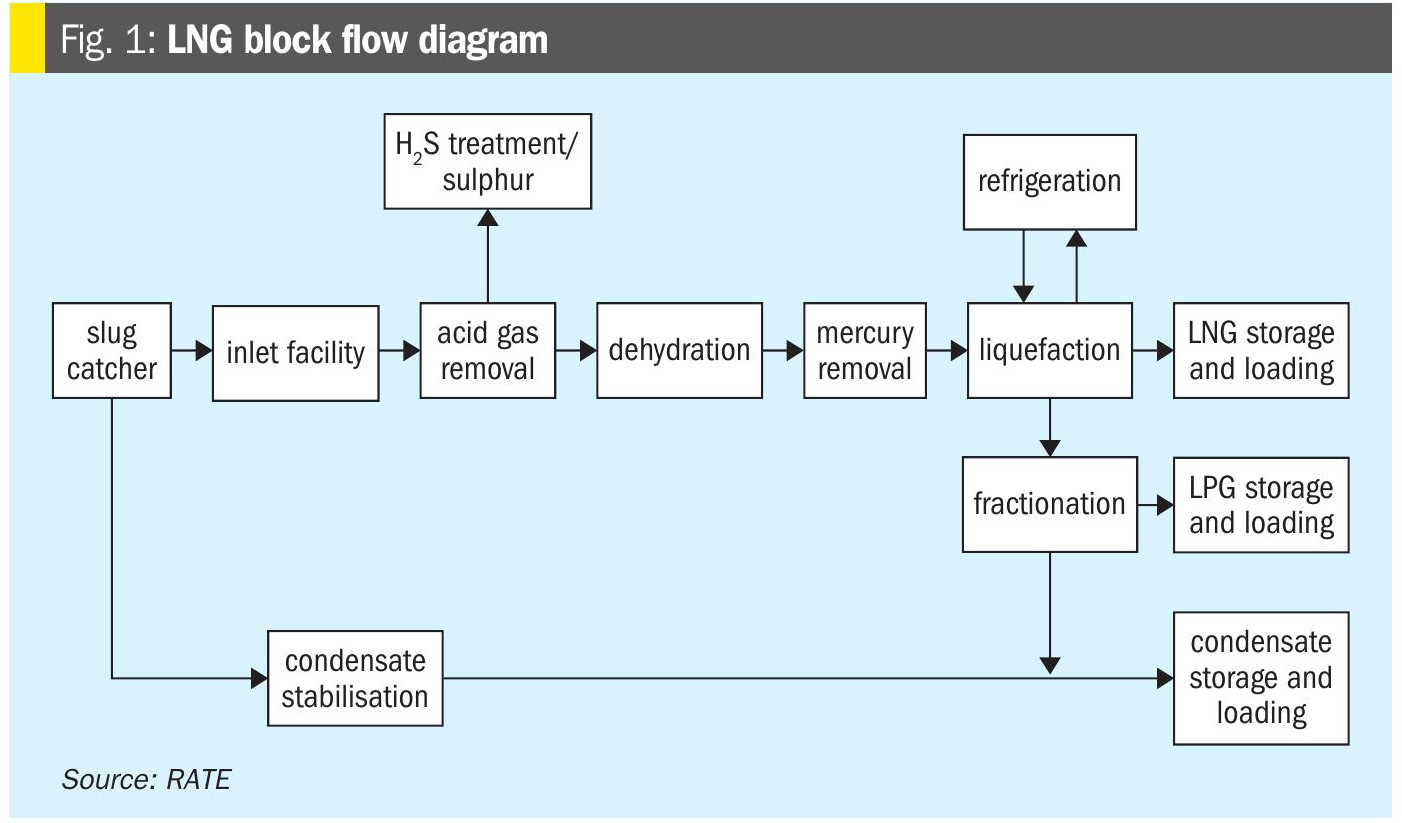
An LNG plant typically contains a number of discrete unit operations. These include:
- acid gas removal;
- dehydration;
- mercury removal;
- fractionation;
- liquefaction;
- storage (LNG, LPG, condensate and refrigerant);
- loading.
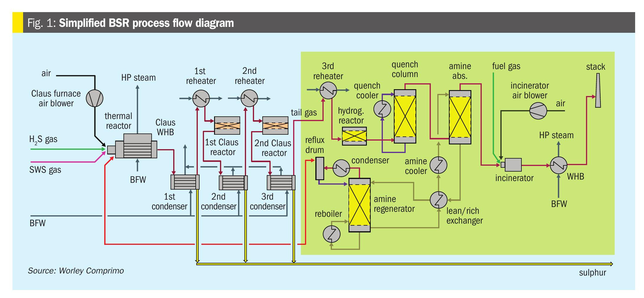
These units are shown schematically in the LNG block flow diagram in Fig. 1.
The acid gas removal required depends on H2S and CO2 contents of the natural gas and complete technology evaluations are required.
The block diagram in Fig. 2 represents an LNG application with higher H2S content. However, even though the H2S content is higher, it is still considered a lean H2S gas, and acid gas enrichment may be required.
The acid gas removal block is shown in detail in Fig. 2.
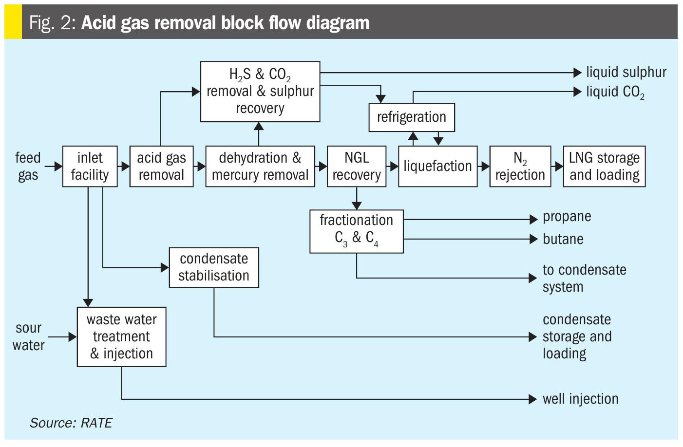
The schemes used for each unit are listed below:
- Acid gas removal solvent: aMDEA;
- Molecular sieve for dehydration and mercaptan removal;
- Carbon beds for mercury removal;
- Selexol is used as the regeneration unit or polishing unit to treat the fuel gas used in the molecular sieve to absorb the sulphur compounds and heavy hydrocarbons;
- Selexol specification: less than 10 ppmv of H2S and less than 50 ppm of sulphur compounds;
- Sulphur recovery includes:
- Acid gas enrichment unit with common regeneration system with the tail gas unit
- Solvent was selected to meet the tail gas absorber requirement of less than 10 ppmv of H2S
- Rich acid gas to conventional Claus unit, and Ti catalyst used in the first catalyst bed
- Conventional tail gas unit with low temperature hydrogenation catalyst and RATE patented technology hydrolysis reactor after the hydrogenation reactor
- RATE sulphur degassing with option of inside or outside pit
- Incineration is a forced draft incinerator with heat recovery system
- RATE CO2 liquefaction technology.
Carbon dioxide: CO2 is very common, its concentration and its evolution with time should be well known as a basis for the sizing the acid gas removal unit. It has to be remembered that CO2 will freeze at the temperature of the cryogenic exchanger and rapidly plug it. It is a similar operational problem as for heavy hydrocarbons as CO2 is soluble, to some extent, in the LNG. Hence by significantly reducing LNG production, the exchanger can after some hours be cleared of the frozen CO2. This incident does not need a complete warm-up of the exchanger but should be avoided by proper design.
Mercaptans: The problem with mercaptans (RSH) is similar to that of H2S but more difficult to solve. The mercaptan specification in LNG is expressed as “total sulphur” content (including H2S, COS) and is generally around 30 mg of “total sulphur” per Nm3 of re-gassed LNG. Knowledge of the RSH content in the feed gas allows the design of the mercaptan removal unit(s). The handling of the mercaptans is different according to the chemical nature of the mercaptans. Therefore, a detailed breakdown of the mercaptans by components has to be looked for and not only a total amount.
Aromatics: Aromatics are absorbed in large quantities by active carbon which is the basic constituent of some mercury removal catalysts. Hence if aromatics quantities are too high they saturate the mercury removal catalyst which will then require replacement.
Water: Water can create hydrates in the incoming pipeline and lead to plugging problems. Hence the water dew point of the incoming gas should be known or specified for new installations. Moreover, as most of the acid gas removal units operate with an aqueous solvent (DEA, DGA, K2 CO3 …), the gas downstream of the unit is water saturated. The train inlet water content is important to know to estimate the process water consumption to saturate the gas and consequently its impact on the desalination plants to produce this process water. Contrary to CO2 or heavy hydrocarbons, frozen water or hydrates have a higher volume in the solid state and therefore trend to damage the main heat exchanger passes by expansion.
Sulphur recovery technologies for H2 S in LNG applications
When hydrogen sulphide (H2S) is removed from LNG feed gas in sufficient volumes, typically from feeds with higher H2S concentrations or large gas flow rates, the extracted acid gas can be processed in a sulphur recovery unit (SRU) to convert H2S into elemental sulphur. This not only mitigates environmental emissions but also produces a valuable byproduct for sale in markets like fertilizers and chemicals. Sulphur recovery efficiencies are often required to exceed 99.9% to comply with stringent regulations on SO2 emissions.
In liquefied natural gas (LNG) production, feed gas often contains lean hydrogen sulphide (H2S) concentrations, typically below 10 ppmv, particularly when sourced from pipeline-quality gas. LNG specifications require H2S to be reduced to less than 4 ppmv to prevent corrosion, toxicity, and freezing during liquefaction. For low H2S concentrations, conventional large-scale amine units can be inefficient due to low partial pressures, increasing capital and operational costs. However,when H2S volumes are significant due to higher concentrations or large gas flow rates, removal followed by processing in a sulphur recovery unit (SRU) becomes viable.
The choice of H2S removal method depends on inlet concentration, gas flow rate, co-contaminants, and economic factors. For lean H2S (<10 ppm) with low to moderate gas volumes, scavengers or adsorption beds are cost-effective, avoiding the need for SRUs. When H2S concentrations or gas volumes are higher (e.g., large-scale LNG plants processing), amine absorption coupled with an SRU becomes viable, leveraging sulphur recovery to offset costs. A hybrid approach, using scavengers or sieves for polishing and amines for bulk removal with SRU integration, may optimise performance in facilities with variable feed compositions. Future trends may favour compact SRU designs or bio-based methods to enhance sustainability for lean H2S management.
Technology selection depends on acid gas composition, sulphur production rate and regulatory requirements. For LNG, integration with upstream amine or membrane units ensures efficient H2S routing to the SRU, with tail gas recycling enhancing overall performance.
The non-conventional technologies such as liquid redox processes, LO-CAT, Sulferox and Thiopaq, result in the formation of a sulphur cake that has to be disposed.
Lean acid gas in a Claus SRU can result in an unstable flame temperature, an insufficient temperature in the thermal reactor for HC destruction, which can cause plugging, lower sulphur recovery, carbon laydown on the catalyst leading to a shorter catalyst life and finally unscheduled plant shutdowns.
In order to overcome these issues, the conventional Claus-type process can be applied but may require additional features to establish a stable operation.
- Direct catalytic stages without thermal section (patented by RATE, Fig. 3) – eliminates the reaction furnace and the burner, with Claus or sub dew point stages up to 30% H2S concentration.
- Provide acid gas enrichment before the Claus unit – full acid gas enrichment or common regeneration with the tail gas unit;
- Acid gas feed preheat and combustion air preheat – to increase the flame temperature of the Claus reaction furnace;
- Supplemental fuel gas burning – a technique often employed to raise the flame temperature while processing acid gas feed of low H2S concentrations in a sulphur plant;
- Staged oxygen enrichment technology – oxygen enrichment technology is ideal for raising the flame temperature of the Claus reaction furnace especially for acid gas of low H2 S concentration, if oxygen is available;
- RICH MAX partial acid gas enrichment in the TGU (patented by RATE, Fig. 4) – partial acid gas is sent to TGU absorber;
- Acid gas bypass;
- Hydrolysis reactor after the hydrogenation reactor in the TGU (patented by RATE, Fig. 5).
Fig. 3 represents the scheme for lean acid gas.
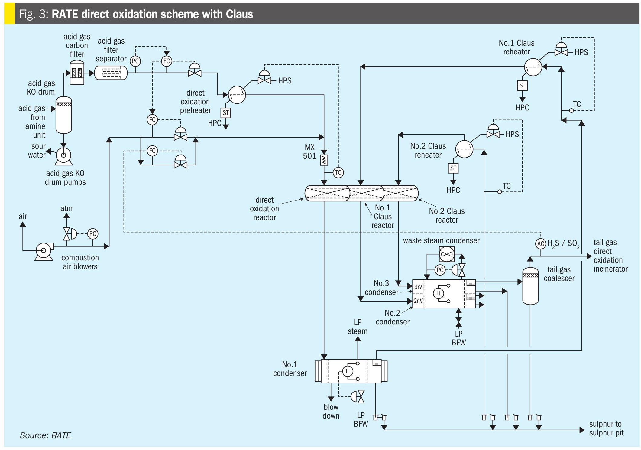
The direct oxidation unit becomes the primary sulphur recovery unit. The direct oxidation process efficiently recovers sulphur from gas streams containing from as little as 2% H2S to over 30% H2S, whereas Claus plants work best when their feeds contain at least 30% H2S. The installation of a direct oxidation unit instead of a Claus unit eliminates the need for an upstream acid gas enrichment unit to further increase the H2S concentration.
The first major breakthrough in direct conversion of H2S feed streams came with the introduction of a newly developed catalyst. The new direct oxidation catalyst selectively oxidises H2S to sulphur with air at low temperature without forming SO3 or oxidising light saturated hydrocarbons.
It is theorised that the direct oxidation reaction, is fast and occurs in the upper few inches of the bed and that the Claus reaction, occurs in the remainder of the bed. Heat released by the reactions raises the temperature in the direct oxidation reactor and sets a limit on the conversion to sulphur, because high temperature is less favourable to complete conversion. The temperature rise, and reduction in equilibrium conversion, is the reason for limiting the feed H2S concentration.
With 5% H2S in the feed the outlet temperature is near 700ºF/370°C, which is a reasonable compromise between carbon steel corrosion and reduction in Claus equilibrium. Above 5% H2S in the feed, the “recycle” mode, is used. The difference in the two flow schemes is the addition of a recycle blower to recycle some of the cool vapour from the direct oxidation reactor condenser to control the temperature rise in the direct oxidation reactor. Note that all combustion air is introduced ahead of the first (direct oxidation) reactor and none is injected ahead of the other (Claus) reactors. This configuration requires the H2S/SO2 “tail gas ratio” to be controlled close to 2.0, as in standard Claus units.
The direct oxidation processes are based upon direct oxidation catalysts. These materials catalyse the oxidation of hydrogen sulphide and sulphur vapour to sulphur dioxide. They also catalyse the Claus reaction, the production of elemental sulphur from hydrogen sulphide and sulphur dioxide by the following reactions:
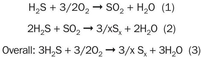
These catalysts do not catalyse the formation of SO3 and consequently, they do not sulphate during operation, nor do they catalyze the oxidation of hydrogen, ammonia, or light hydrocarbons. Furthermore, because they operate at much lower temperatures than a reaction furnace, they do not produce carbonyl sulphide or carbon disulphide.
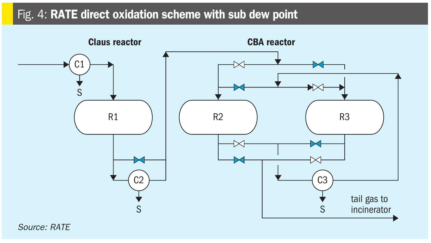
In order to achieve higher recovery, the Claus section can be designed with sub dew point reactors as shown in Fig. 4.
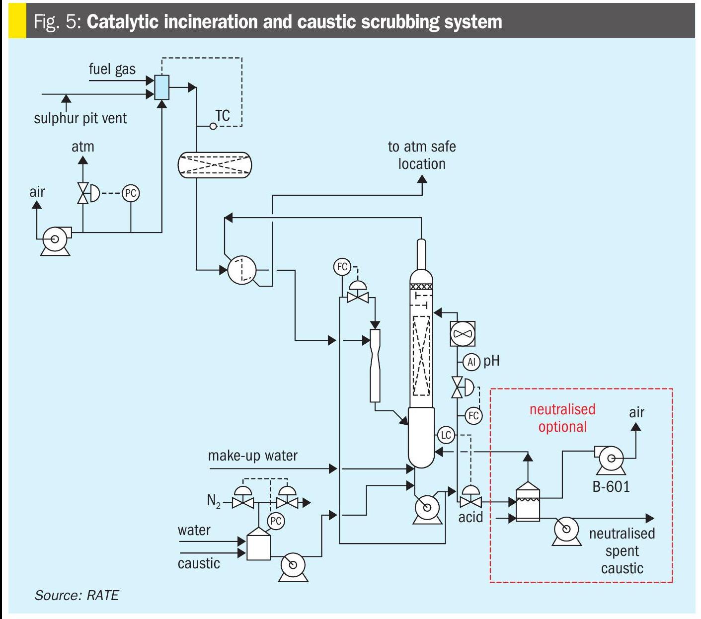
The tail gas from the tail gas unit along with the pit vent from the sulphur pit is sent to the catalytic incinerator. The residual H2S and other sulphur compounds in this gas stream are oxidised to convert all the sulphur compounds to SO2. The incinerator is a forced draft incinerator, and heat can be recovered.
The incineration section consists of a fired heater, air blower direct oxidation reactor followed by the caustic scrubber.
The effluent gas from the direct oxidation reactor is scrubbed in a venturi scrubber by intimate contact with a 10 wt-%caustic solution. During the liquid vapour contact a portion of the SO2 is removed from the vapour and the gas is cooled.
The liquid-vapour mixture then flows to the caustic scrubber. The vapour flows up through the packed bed of the caustic scrubber against a counter-current stream of 10 wt-% caustic solution to scrub the remaining SO2 from the tail gas. The treated gas leaving the caustic scrubber will contain low ppm levels of SO2.
Due to the temperature of the gas leaving the reactor there is a constant vaporisation of water in the caustic scrubber which needs to be made up. This make-up water is added to the column at the upper bubble trays to knock any remaining entrained caustic out of the vapour to minimise caustic loss. The caustic system uses a non-regenerable caustic (NaOH in water) to remove the SO2 from the tail gas. The SO2 that is removed slowly decreases the caustic strength of the solution so fresh caustic is added to replace the spent caustic.
Fig. 5 represents catalytic incineration with the caustic scrubber system.
As described above, the direct oxidation scheme can replace the non-conventional scheme by producing high quality sulphur instead of sulphur-cake and without generating another waste stream.
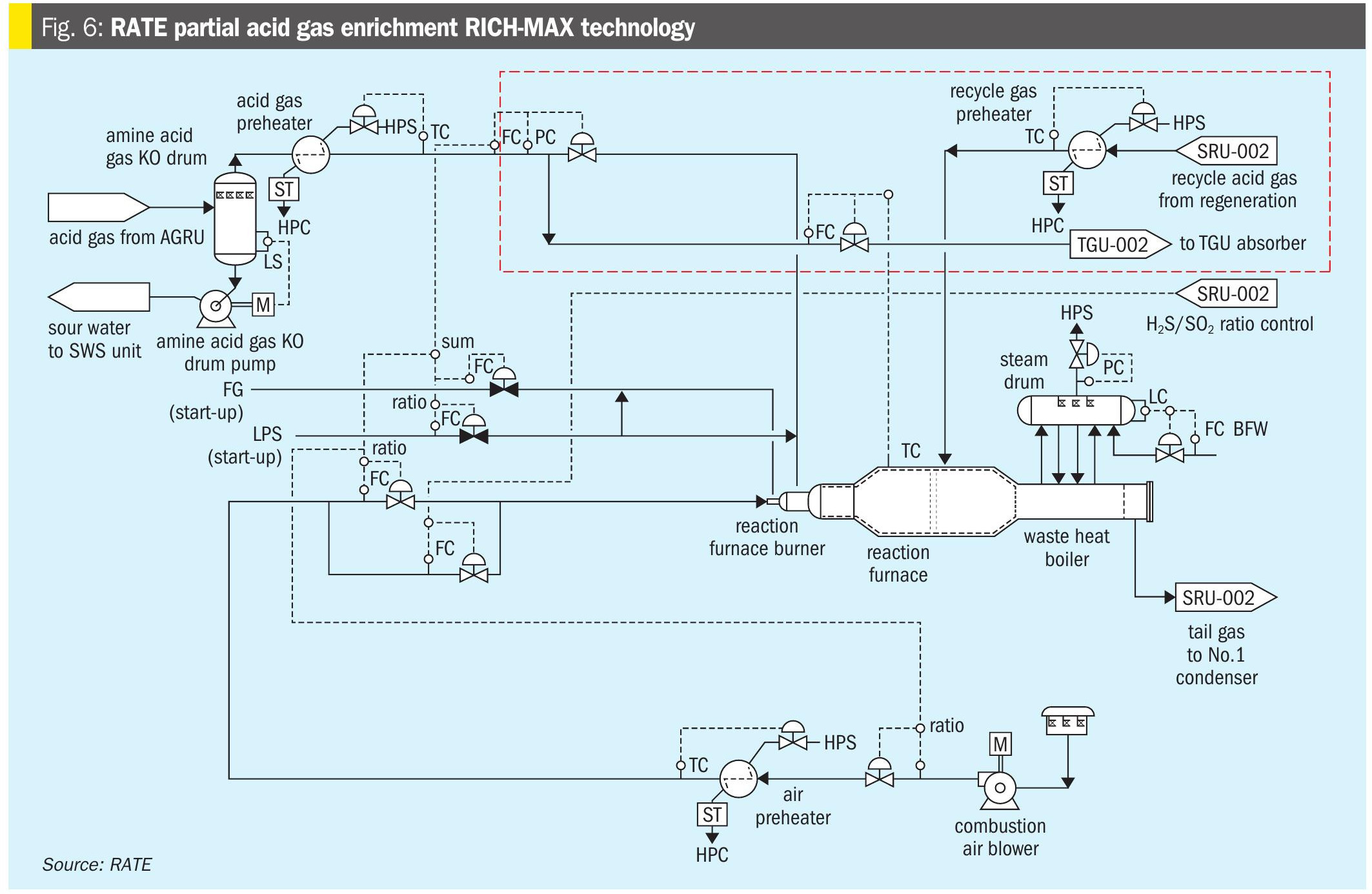
As shown in Fig. 6, RATE’s partial enrichment scheme RICH-MAX is a patented process where the H2S concentration is marginal. It would be too expensive to have independent acid gas enrichment upstream of the Claus unit, but by partially enriching the H2S, using the TGU absorber, an adequate combustion temperature in the reaction furnace can be achieved. In this scheme a portion of the SRU feed is sent to the TGU absorber to enrich the H2S and the recycle is reheated and sent to the second zone of the reaction furnace.
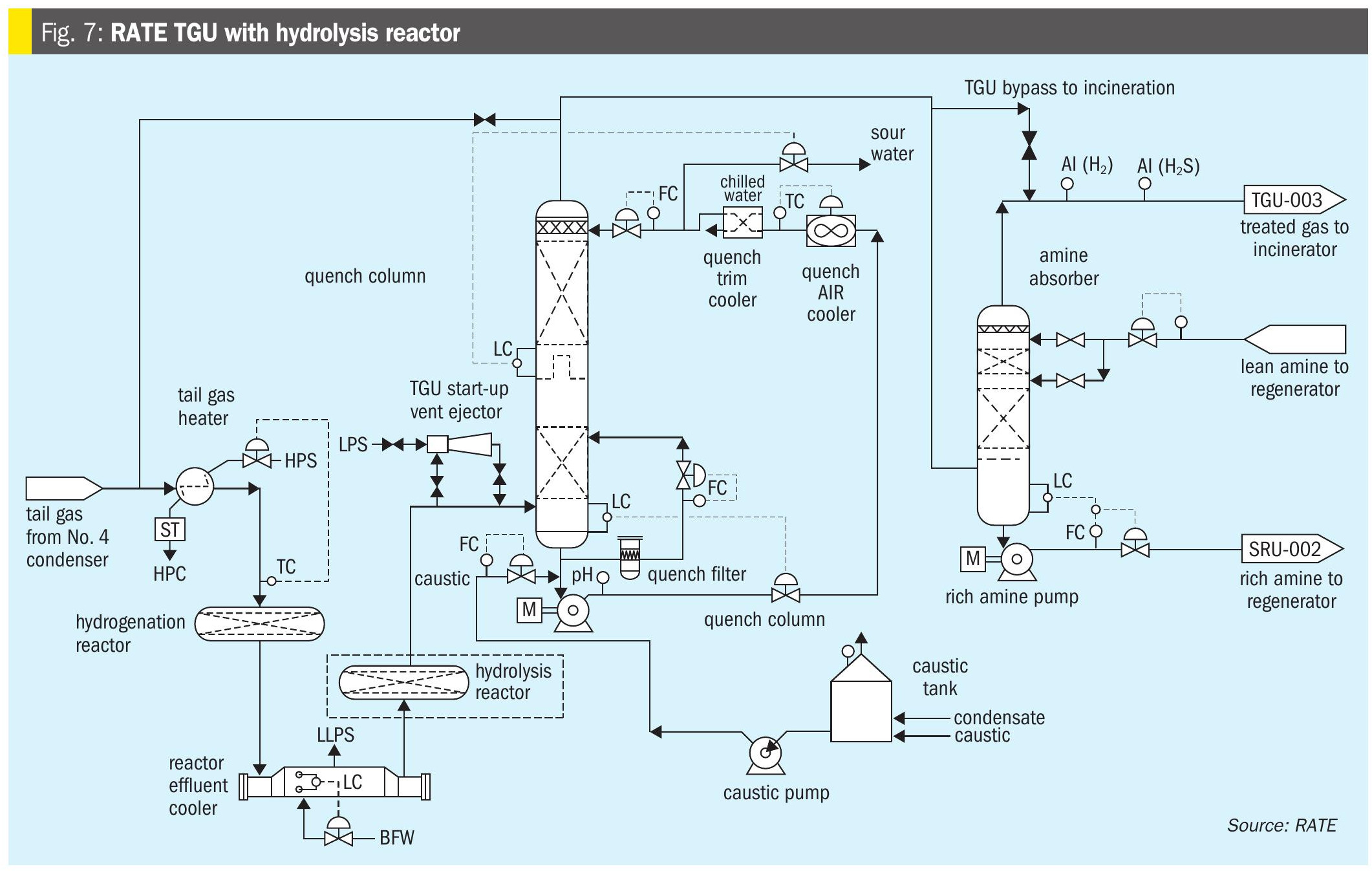
As shown in Fig. 7, the lean H2S gases in the sulphur recovery unit produce COS and CS2 as unwanted by-products in the thermal section of the Claus unit. Even though, in the first catalytic reactor titanium catalyst is used to hydrolyse COS and CS2 they are not fully hydrolysed and would have an impact on the overall SRU/ TGU recovery. According to operating data and the performance test 50-100 ppm of COS and CS2 are in the gas leaving the hydrogenation reactor in the tail gas. RATE’s hydrolysis reactor technology after the hydrogenation reactor will hydrolyse the remaining COS and CS2 and the incineration stack would meet the World Bank SO2 emission of 150 mg/Nm3.
CO2 liquefaction reinjection
CO2 recovery reduces greenhouse gas emissions in LNG sulphur plants [Global CCS Institute, 2024].
RATE’s CO2 liquefaction technology manages emissions. CO2 from SRU amine units, which risks freezing in cryogenic exchangers, is compressed and liquefied for reinjection, enhancing sustainability.
Challenges facing LNG projects
LNG has become a vital component of the global energy landscape, serving as a cleaner alternative to coal and oil while supporting energy security in a transitioning world. LNG projects involve the extraction, liquefaction, transportation, and regasification of natural gas, enabling its trade across continents. Despite its growing importance, LNG projects face significant challenges that impact their development, profitability, and sustainability.
Regulatory and legal challenges
One of the primary obstacles for LNG projects is navigating complex and evolving regulatory frameworks, which create uncertainty for developers and buyers, stalling final investment decisions. These challenges highlight the tension between economic development and regulatory compliance, particularly in regions with stringent environmental standards.
Economic and market uncertainties
LNG projects require substantial capital investments, often costing tens of billions of dollars, and rely on predictable profitability over long timelines. However, fluctuating market conditions pose significant risks. A potential global oversupply of LNG, projected to reach 63 million tons by 2030, could depress prices and reduce profitability. Rising construction costs, driven by tariffs on materials like cryogenic steel and labour shortages, further complicate project economics. For instance, the Golden Pass project in Texas faced delays after a contractor bankruptcy led to cost overruns, pushing its start date to late 2025. Moreover, price sensitivity in key markets like Asia, where demand is strong but buyers are quick to shift to cheaper alternatives like coal, adds uncertainty to long-term demand forecasts. These economic challenges require developers to balance high upfront costs with volatile market dynamics.
Environmental and social concerns
As a fossil fuel, LNG faces scrutiny for its environmental impact, despite emitting less carbon dioxide than coal. Environmental groups and local communities often oppose projects, citing harm to ecosystems and public health.
Additionally, the industry is under pressure to reduce greenhouse gas emissions, particularly methane, which can leak during production and transportation. While technologies like carbon capture and storage (CCS) offer potential solutions, their adoption increases costs and complexity. Balancing energy demands with environmental and social responsibilities remains a critical challenge for LNG developers.
Geopolitical and supply chain risks
Geopolitical tensions and supply chain disruptions add further complexity to LNG projects. Global supply chains for LNG infrastructure are vulnerable to disruptions.
Geopolitical risks, can disrupt supply and increase costs and competition from other LNG exporters, where shorter shipping routes give competitors an edge, make it difficult for developers to secure long-term contracts and maintain a competitive position in the global market.
Conclusion
LNG remains a cornerstone of global energy security, bridging the gap between remote gas resources and consumption centres.
Effective management of lean H2S through tailored removal and sulphur recovery technologies is critical to meeting stringent LNG specifications (<4 ppmv H2S) and environmental regulations (>99.9% sulphur recovery). However, LNG projects face multifaceted hurdles, including regulatory complexities, market volatility, and geopolitical risks.
By leveraging advancements in modular liquefaction, digital twins, and low-emission SRUs, the industry can enhance resilience and align with net-zero goals by 2050.
References