Sulphur 410 Jan-Feb 2024
31 January 2024
Case study: Replacement of upper part of a co-current flow quench tower
This case study reports on the successful collaboration of two experienced partner companies to replace the problematic upper part of a co-current flow quench tower in a spent acid plant and shows the benefits of using resistant, pre-lined workshop fabricated equipment.
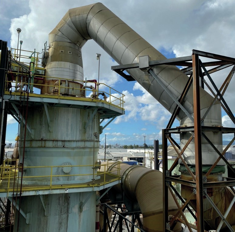
Eco Services’ Dominguez Plant operates a spend acid unit production facility in Long Beach, California. After the spent acid furnace and the waste heat boiler the acid gas with a temperature of 358°C has to be cleaned and cooled down to 80°C in a co-current flow quench tower (see below).
The original quench tower was built in 1989 for the predecessor company Stauffer.
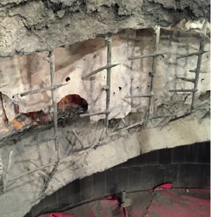
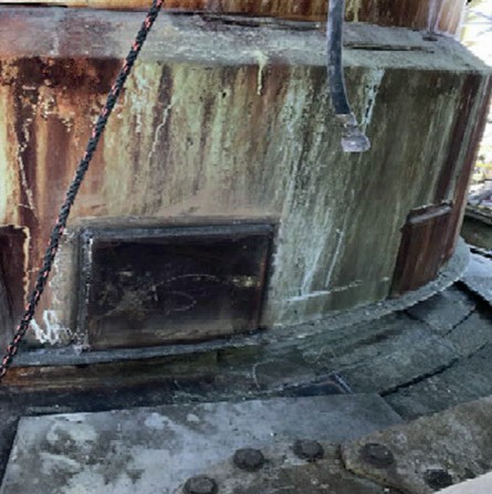
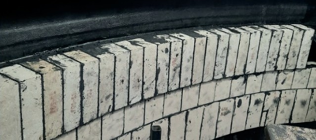
Quench tower damage
Due to the high thermal, chemical and mechanical stress in the quench tower the acid resistant brick lining system had suffered from frequent damage during its 30 years of operation (see below).
The problem
Eco Services had to repair the acid resistant brick lining system at every turnaround. The costs for the repairs were very high and the duration of the shutdowns was often 2-3 weeks long. Eco Services used several different materials for the repair, including monolithic spray systems with anchors etc. several times but the materials were not resistant. Due to unforeseen damage in the upper part of the quench tower, Eco Services experienced lost production and high maintenance costs associated with this tower.
Eco Services explained the issues with this acid resistant brick lining system to STEULER-KCH GmbH at the Sulphur + Sulphuric Acid Conference in Houston in 2020 and asked for a repair proposal.
After receiving the inquiry and reviewing the detailed technical information (steel and brick lining drawings, complete stress data, process description, loads of the piping etc.) STEULER-KCH GmbH recommended installing a new, acid and heat resistant brick lining system that would be installed in their workshop in Germany and then delivered together with the upper part of the steel apparatuses as a pre-lined workshop fabricated equipment ready for service on site to the Martinez Plant in LA.
Besides the detailed technical design for the lining system STEULER-KCH GmbH was also responsible for designing, building, and delivering the new, necessary upper steel part.
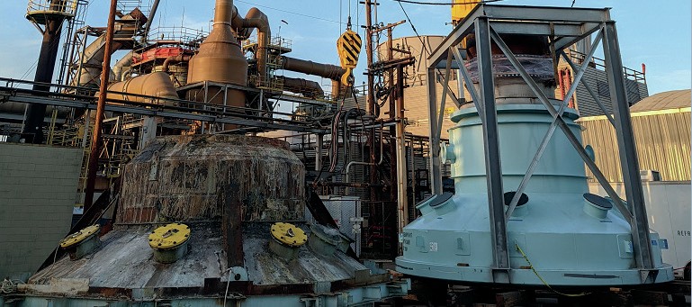
Pictures below show various manufacturing and installation stages involved of the project. During a shutdown the damaged existing upper part of the quench tower was removed and the new pre-brick lined equipment was installed. The works on site was carried out by Eco Services contractors under technical supervision of a STEULER-KCH GmbH rubber-and brick lining specialist.
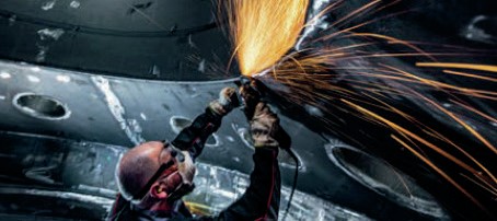
1. Step: Steel fabrication
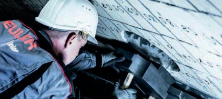
2. Step: Surface treatment
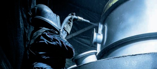
3. Step: Rubber lining and outside painting
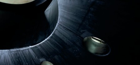
4. Step: Vulcanisation
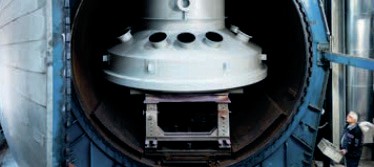
5. Step: Brick lining
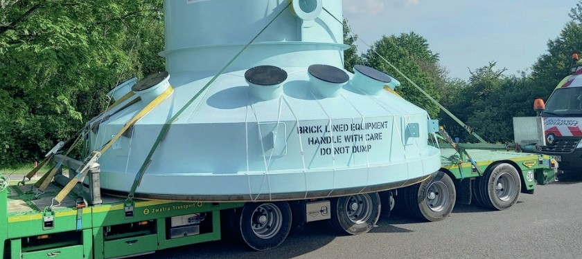
6. Step: Transportation to site
7. Step: Installation on site
Main benefits
The main benefits of the pre-lined lining systems in this case were:
- everything delivered from a single source;
- execution of the highest level in the workshop;
- no expensive weather protection and scaffolding on site;
- lower travel and accommodation expenses;
- no loss of time on site due to internal regulations;
- no harmful influences (gas, steam, acid etc.) during work on site;
- better and safer cost control;
- no visa application and safety instruction on site for many fitters;
- very limited time on site and extreme reduction of shutdown period;
- working conditions/environment under defined conditions in the workshop;
- no transport costs for materials and tools to site and back;
- significantly lower cost for installation.