Nitrogen+Syngas 398 Nov-Dec 2025
24 November 2025
Selecting the right cooling technology
FERTILIZER EQUIPMENT
Selecting the right cooling technology
Advances in cooling technology are providing fertilizer facilities with new options when it comes to upgrading outdated equipment and improving environmental sustainability of their existing operations. Igor Makarenko of Solex Thermal Science explores cooling strategies to improve operational efficiencies while also reducing their energy consumption, greenhouse gas emissions and overall carbon footprint.
For fertilizer operators looking to either improve, optimise or replace existing equipment, there is no simple answer to the question of what’s the best cooling technology to handle their process needs. Given the critical role the fertilizer industry plays in global food security, it is essential to evaluate all modern technologies to ensure the world continues to be fed.
For example, product quality plays a critical role in optimising nutrient use efficiency, reducing environmental impact and improving crop yields. Proper drying (e.g., removing excess moisture from the fertilizer using heat) together with cooling represents a pivotal step in preventing clumping. Cooling, meanwhile, ensures the product is stabilised and at ideal temperature for storage and transport, thereby preserving the quality and value of the finished product.
Yet at the same time, operators also need to evaluate whether cooling technologies meet their decarbonisation needs. The fertilizer industry is a significant contributor to global greenhouse gas (GHG) emissions due to the energy required to produce a finished product. According to data collected by member organisations of the International Fertilizer Association (IFA), it is estimated that 1.3% of global carbon dioxide (CO2 ) emissions are generated from the production of mineral fertilizers1. Implementing decarbonisation strategies at certain stages of fertilizer production is vital for the industry as it seeks to reduce its collective carbon footprint.
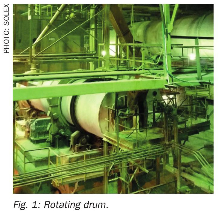
Rotary drums
Rotary drums are a common method for drying and cooling fertilizers given their ability to process different grades and operate with variable feed inlet conditions. In a typical rotary indirect drum, material introduced at one end of the equipment is lifted and dropped numerous times as the material moves through the drum.
Strengths: Robust, well-understood operation, tolerant to feed variability and tramp materials, and available in large sizes with straightforward maintenance programs.
Some considerations with rotary drums include:
• Excessive fine particle loss: Fine particles can be carried away with the warm exhaust air, leading to product loss and potential environmental concerns. Adjusting air velocity and using cyclones, bag filters, scrubbers, etc. can help minimise this issue.
• Sticky materials: Some fertilizers are more hygroscopic nature than others, and may become sticky during the cooling process, causing agglomeration and affecting flowability. Regular cleaning of equipment internals helps to avoid buildup, which adds extra weight to the drum and places unnecessary stress on all components.
• Non-uniform cooling: Inconsistent air flow or temperature distribution can result in uneven cooling, affecting product quality (e.g., transferring hot material to the storage). Regular maintenance of the air distribution system and careful monitoring of operational parameters (e.g., correct bed depth) are essential to ensure uniform cooling.
• Maintenance requirements: Rotary drums are generally low maintenance. However, there are several moving parts that require proper lubrication, including bearings, chains, gears, reducers and graphite blocks. Furthermore, drum coolers require regular tire and trunnion grinding, alignment, maintaining proper drum float/distribution systems and checking for wear and tear.
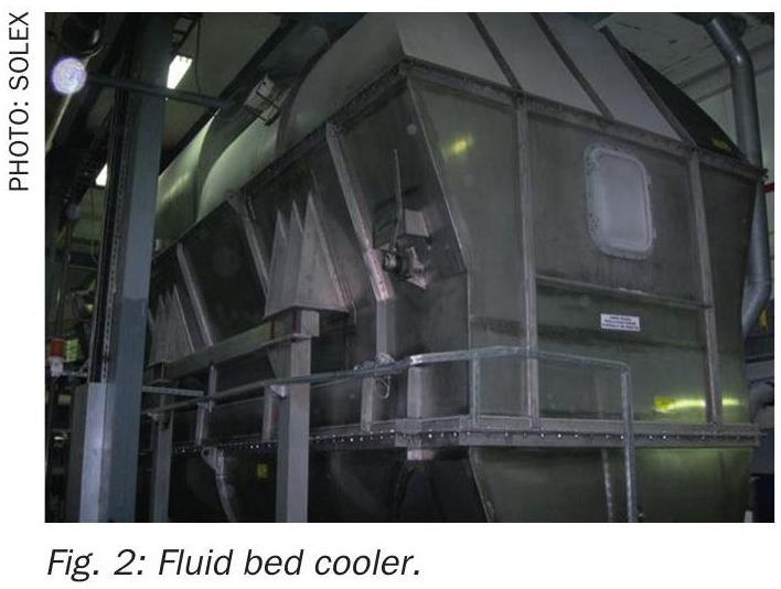
Fluid beds
Fluidised bed coolers, which includes vibrating fluid beds, are also commonly used to dry and cool fertilizers. In this process, large volumes of ambient air is used to directly fluidise the material. This enables the product bed to flow from one end to the other, drying and then cooling (it can be also standalone cooling) as it moves.
Strengths: High heat and mass-transfer rates, compact for combined drying/ cooling, and easy integration with waste-heat or heat-recovery air circuits
The air has two functions in fluid bed technology. First, it creates the fluidised state of the material, enabling the product to flow. Second, it either heats or dries the material through direct contact. Fluid bed machines require either dedicated or are part of larger common air-treatment systems to comply with air emission regulations.
It’s common for fertilizer producers to use a combined fluid-bed system, with the first unit operating as a dryer and the second part as a cooler. Alternatively, producers can use a combination of a rotary drum dryer and fluid bed cooler. In this arrangement, the air exhausted from the fluid bed cooler can then be used in the rotary drum dryer, reducing the amount of ambient air required in the process and, being already preheated, saving on energy intake.
Traditional cooling equipment such as fluidised beds and rotary drums require large energy inputs (e.g., high horsepower fans and, in some cases, chillers) to get the job done. This is a challenge for producers who are already facing overall high energy costs at their plants.
Some considerations with fluid beds include:
• Poor fluidisation: This occurs when the material does not fluidise properly, leading to clumping or channelling across the moving bed. It can be caused by non-uniform particle size (including dust content) and moisture content. Ensuring uniform material characteristics, proper design of the distributor plate and careful operating practices to ensure maintaining correct bed depth can help address this issue.
• Excessive fine particle loss: Fine particles can be carried away with the warm exhaust air, leading to product loss and potential environmental concerns. Adjusting air velocity and using cyclones, bag filters, scrubbers etc. can help minimise this issue.
• Sticky materials: Some fertilizers are more hygroscopic in nature than others and may become sticky during the cooling process, causing agglomeration and affecting flowability. Regular cleaning/ maintenance of the perforated plate is necessary to ensure consistent operation.
• Non-uniform cooling: Inconsistent airflow or temperature distribution can result in uneven cooling, affecting product quality (e.g., transferring hot material to the storage). Regular maintenance of the air distribution system and careful monitoring of operational parameters (including correct bed depth) are essential to ensure uniform cooling.
• Maintenance requirements: Fluid beds require regular maintenance to keep them running efficiently. This includes cleaning air distribution systems, checking for wear and tear and ensuring proper lubrication of moving parts.
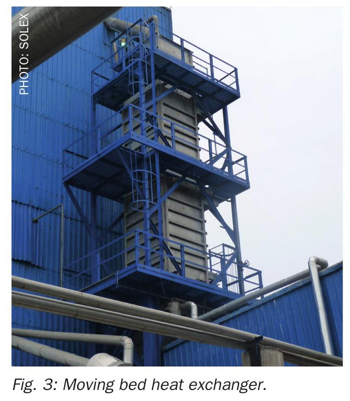
Plate-based heat exchangers
Plate-based heat exchangers (also known as bulk flow coolers) at the cooling stage of production offers operators the opportunity to improve the energy efficiency of their existing processes, with the added benefit of being able to use less air and reduce opex penalties (e.g. energy inputs to drive circulating pumps).
The technology blends the thermal efficiency of plate heat exchange design with the science of uniform mass flow to cool granular bulk solids such as fertilizers. First, a bucket elevator brings the fertilizer from the dryer, granulator or prilling tower into the inlet hopper of the heat exchanger at temperatures typically around 55°C to 85°C. The flowrate of product, ranging from 1 to 200 t/h, then flows at a controlled speed through the heat exchanger bank(s), usually 0.3 m per minute, while cooling water at 18°C to 25°C flows counter-currently within the internal channels of the plates.
The flow of fertilizer is controlled by a discharge extraction device equipped with a variable frequency drive (VFD) that ensures uniform mass flow and even product temperatures at the outlet – typically 30°C to 42°C to avoid caking during storage, or in big-bags or in transit. A level probe/transmitter in the inlet hopper maintains the proper product level as it controls the VFD on the feeder.
The heat exchanger is static, with the only moving part being the oscillating feeder at the outlet. Likewise, the unit has side access doors over the height of each plate bank to allow for cleaning and maintenance. The number of heat exchanger banks required is dependent on the duty of the process conditions and necessary surface area to meet the cooling temperature target.
If the moving bed heat exchanger (MBHE) is installed in a hot, humid location, a small amount (1 000 Nm³/h to 2 500 Nm³/h) of, typically, dehumidified purge air needs to be injected between the heat exchanger banks to prevent condensation and caking from forming inside the column.
MBHEs can easily be retrofitted into existing facilities, as they have a small installation footprint (less than 2 m x 2 m) and can be used in conjunction with current equipment. They can also be installed and operated as secondary coolers after existing fluid bed or drum coolers if additional cooling is required due to a capacity increase, this revamp allows for increased production capacity, as well as a higher quality (at the required temperature) of the finished product.
The water source is typically existing plant cooling tower water, natural water sources, chilled water circuit or chilled ammonia. In some cases natural water sources (e.g., river, or sea water) can be used by incorporating a closed-loop fluid temperature control circuit. The system can also operate as a completely standalone system (e.g., no water intake from operator is required) via a dedicated closed-loop circuit using a standalone electric chiller and free-cooling non-evaporative towers.
With the use of a plate-based heat exchangers in fertilizer cooling operations, operators benefit from the following advantages:
• Electrical demand as low as ~0.4 kWh/ tonne (site- and product-dependent, excluding optional purge-air dehumidification) of fertilizer.
• Zero product contamination and degradation of granules/prills because of the slow and controlled movement of the product, and because product does not come in contact with air or water.
• The low downward velocity of the product bed between the plates mitigates the creation of fines/dust. Producers can expect amount of dust in worst-case scenarios equal to amount at the feed point.
• Residence time inside the heat exchanger and heat transfer between particles in narrow separate columns providing accurate uniform heat exchange and desired product temperature at the exit of the cooler.
• No large horsepower process-air fans required, eliminating a major exhaust stream and its abatement load.
• Material of construction provides required integrity (e.g. stainless steel 304L, 316L, 254 SMO etc.)
• Constant temperature in storage and direct packaging independent of ambient conditions means no product caking.
• A pneumatically driven discharge device (e.g., gate feeder) is the only moving part in this unit, and requires minimal maintenance.
Some considerations with plate-based heat exchangers include:
• Caking: This occurs during the cooling process when the critical relative humidity temperature and interstitial air dew point exceeds the plate surface temperature. The remedy to this is to use a calculated amount of purge air and a cooling water regime (flow rate and temperature)
• Physical plugging: When the product contains various particles sizes, this can block
space between the plates (calculated for each fertilizer separately). A proper cleaning system upstream and plate spacing in the heat exchanger can successfully preventing this from happening.
• Cooling-water quality: Closed loops no longer require tight control of scaling/corrosion and filtration to minimise plate fouling.
Technology considerations
Choosing the right fertilizer cooling technology depends on several factors, including the type of fertilizer, production requirements and desired outcomes. The following represents some key considerations:
Type of fertilizer: Different fertilizers have varying cooling needs. For example, hygroscopic fertilizers such as potash and phosphate bases are more prone to caking, therefore require lower dew point of purge air to prevent clumping. AN-based fertilizers, meanwhile, require a greater heat flow area to provide effective cooling.
Cooling efficiency: Commonly used cooling technologies include fluid beds, rotary drums and plate-based heat exchangers. Fluid bed coolers offer cooling by suspending solid material in a flow with chilled or ambient air. Rotary coolers tumble material in a rotating drum also with chilled or ambient air. Plate-based heat exchangers provide an indirect cooling options, with a packed bed of solids moving downward between stainless-steel plates which contain a countercurrent flow of cold or chilled water.
Product integrity (including coated products): Preserving fertilizer integrity during the cooling process is crucial to maintaining product size, quality and longevity, while also preventing issues such caking and nutrient loss. Fluidisation, as well as tumbling actions, can negatively impact product integrity (e.g., creates dust) due to the mechanical nature of the heat transfer process. Plate-based heat exchangers do not create dust due to the indirect nature of the heat transfer process. This process also preserves product quality – including the coatings in applications involving coated fertilizers.
Throughput requirements: Considering the production scale and throughput needs, all three technologies have improved their robustness in recent years and have been operating in the field with high throughputs. This was not the case several years ago when rotating equipment was often preferred for higher throughputs, making it suitable for large-scale operations.
Capex/opex: Each technology comes with different associated costs, which can include:
• equipment investment cost (e.g., equipment assets and implementation/installation);
• operating costs (e.g., energy input requirement, maintenance costs and required scheduled downtime);
• costs of post-processing working fluid (e.g., air abatement, CW cooling).
Maintenance and reliability: There are several considerations when evaluating the maintenance requirements and reliability of the cooling equipment:
• Maintenance needs: Rotating equipment such as rotary drum coolers generally requires more frequent maintenance due to the moving parts. This includes regular lubrication, alignment checks and wear-and-tear inspections. Rotary coolers have a well-earned reputation for reliability, operating consistently and without issue for years providing they are regularly maintained.
• Failure modes: Common failure modes include bearing failures, seal leaks and mechanical wear. Proper condition monitoring and preventive maintenance can mitigate these issues.
• Static equipment maintenance needs: Fluid bed coolers typically require less frequent maintenance since it has fewer moving parts. This can lead to lower maintenance costs and downtime. Similarly, plate-based heat exchangers require minimal maintenance due to it being gravity fed through the unit and discharged by a low-speed oscillating pneumatic extraction device.
• Failure modes: Failures in static equipment are often related to corrosion, fouling or structural issues. Regular inspections and cleaning can help prevent these problems.
• Stability: Static equipment tends to be more stable and less prone to mechanical failures, making it a reliable choice for consistent operations.
Cost and availability: Operators must factor in the cost of the equipment and its availability. A few cost considerations when choosing a cooling technology include the degree of difficulty of integrating it into the existing space and required downtime.
Conclusion
When the risk of product quality is in question, cooling in fertilizer production plants is an essential step in product finishing. Furthermore, rising decarbonisation efforts within the fertilizer industry means it’s not just what cooling technologies can do, but how they do it. Today’s solutions demonstrate how these changes are already taking place. For decades, they have acted as cornerstones in the fertilizer production process. In recent years, they have evolved to further help decarbonise operations.
When it comes to selecting the right cooling technology, operators must understand that there is no one-size-fits-all solution. Many different variables will determine the viability of the installed solution. Yet by investing in the right technology solutions, fertilizer producers have an opportunity to meet their operational and decarbonisation goals while still feeding the world of tomorrow.
References